HAL Id: hal-03168845
https://hal.archives-ouvertes.fr/hal-03168845
Submitted on 14 Mar 2021HAL is a multi-disciplinary open access archive for the deposit and dissemination of sci-entific research documents, whether they are pub-lished or not. The documents may come from teaching and research institutions in France or abroad, or from public or private research centers.
L’archive ouverte pluridisciplinaire HAL, est destinée au dépôt et à la diffusion de documents scientifiques de niveau recherche, publiés ou non, émanant des établissements d’enseignement et de recherche français ou étrangers, des laboratoires publics ou privés.
Framework to Relate / Combine Modeling Languages
and Techniques
Rima Al-Ali, Moussa Amrani, Soumyadip Bandyopadhyay, Ankica Barisic,
Fernando Barros, Dominique Blouin, Ferhat Erata, Holger Giese, Mauro
Iacono, Stefan Klikovits, et al.
To cite this version:
Rima Al-Ali, Moussa Amrani, Soumyadip Bandyopadhyay, Ankica Barisic, Fernando Barros, et al.. Framework to Relate / Combine Modeling Languages and Techniques. [Technical Report] COST European Cooperation in Science and Technology. 2017. �hal-03168845�
ICT COST Action IC1404
Framework to Relate / Combine
Modeling Languages and Techniques
Rima Al-Ali, Moussa Amrani, Soumyadip Bandyopadhyay, Ankica
Bariši´c, Fernando Barros, Dominique Blouin, Ferhat Erata, Holger
Giese, Mauro Iacono, Stefan Klikovits, Eva Navarro, Patrizio Pelliccione,
Kuldar Taveter, Bedir Tekinerdogan, Ken Vanherpen
Deliverable: WG1.2
Core Team Document Info
University of Antwerp, Belgium Deliverable WG1.2 New University of Lisbon, Portugal Dissemination Restricted Telecom ParisTech, Paris, France Status Final
Hasso-Plattner Inst., Potsdam, Germany Doc’s Lead Partner Hasso-Plattner Inst. University of Geneva, Switzerland Date January 7, 2019 Charles University, Prague, Czech Republic Version 3.0
University of Manchester, UK Pages 97
University of Namur, Belgium Wageningen University, Netherlands University of Coimbra, Portugal Ege University, Izmir, Turkey
University of Campania Luigi Vanvitelli, Caserta, Italy Tallinn University of Technology, Estonia
Contents
1 Introduction 1
1.1 Ontology Development Approach . . . 2
2 Ontology of Shared Concepts 4 2.1 Ontology Overview . . . 4
2.2 DomainConcept . . . 4
2.2.1 ParadigmDC (Paradigm Domain Concepts) . . . 4
2.2.2 ProcessDC (Process Domain Concepts) . . . 5
2.2.3 RelationDC (Relation Domain Concepts) . . . 5
2.2.4 StakeholderDC (Stakeholder Domain Concepts) . . . 6
2.2.5 ToolDC (Tool Domain Concepts) . . . 7
2.3 Properties . . . 7
3 Ontology of Cyber-Physical Systems 8 3.1 State-of-the-art . . . 8 3.2 Ontology Overview . . . 9 3.2.1 Ontology Diagram . . . 9 3.2.2 Architecture . . . 9 3.3 Ontology Overview . . . 10 3.4 Domain Concepts . . . 10 3.4.1 ApplicationDomainsDC . . . 10 3.4.2 ArchitectureDC . . . 10 3.4.3 QualityRequirementsDC . . . 10 3.4.4 SystemDC . . . 16 3.5 Properties . . . 17
4 Ontology of Multi-Paradigm Modeling 21 4.1 State-of-the-art . . . 21
4.1.1 Models and Modeling Languages: Construction and Execution . . . 22
4.1.2 Model Operations: Construction and Execution . . . 24
4.1.3 Megamodels and other Global Model Management Approaches . . . 26
4.1.4 Multiformalism Modelling Approaches . . . 27
4.2 Ontology Overview . . . 29
4.3 Domain Concepts . . . 29
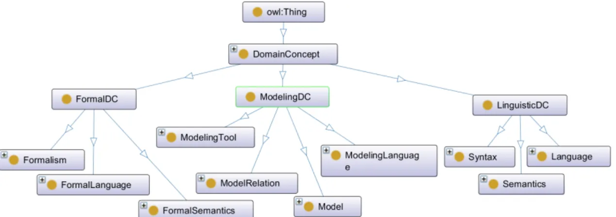
4.3.1 FormalDC . . . 29
4.3.2 FormalismDC . . . 31
CONTENTS
4.3.4 ModelingDC . . . 37
4.4 Properties . . . 39
5 Ontology of Multi-Paradigm Modeling for Cyber-Physical Systems 40 5.1 Introduction . . . 40 5.2 Ontology Overview . . . 40 5.3 Domain Concepts . . . 40 5.3.1 MPM4CPSDC . . . 40 5.4 Properties . . . 41 5.4.1 hasActions . . . 41 5.4.2 hasActivities . . . 41 5.4.3 hasCharacteristic . . . 41 5.4.4 hasChildFormalism . . . 41 5.4.5 hasChildLanguage . . . 41 5.4.6 hasConcerns . . . 41 5.4.7 hasConstraint . . . 42 5.4.8 hasContext . . . 42 5.4.9 hasEvolvedTo . . . 42 5.4.10 hasInput . . . 42 5.4.11 hasInputModel . . . 42 5.4.12 hasLanguage . . . 42 5.4.13 hasMegamodelFragment . . . 43 5.4.14 hasModel . . . 43 5.4.15 hasModelConstraint . . . 43 5.4.16 hasModelOperation . . . 43 5.4.17 hasModelRelation . . . 43 5.4.18 hasNext . . . 44 5.4.19 hasOutput . . . 44 5.4.20 hasOutputModel . . . 44 5.4.21 hasProvider . . . 44 5.4.22 hasPurpose . . . 44 5.4.23 hasRelations . . . 44 5.4.24 hasRole . . . 45 5.4.25 hasStakeholders . . . 45 5.4.26 hasSubFormalismFamily . . . 45 5.4.27 hasSystemPart . . . 45 5.4.28 hasTool . . . 45 5.4.29 hasViewpoint . . . 45 5.4.30 isAppliedTo . . . 46
Framework to Relate / Combine Modeling Languages and Techniques 5.4.31 isAppliedToModel . . . 46 5.4.32 isBasedOnFormalism . . . 46 5.4.33 isCharacterizedBy . . . 46 5.4.34 isConnecting . . . 46 5.4.35 isExtending . . . 47 5.4.36 isExtendingFormalism . . . 47 5.4.37 isPerformedBy . . . 47 5.4.38 isReturningTo . . . 47 5.4.39 isSpecializing . . . 47 5.4.40 isSupportedBy . . . 47 5.4.41 isToolFor . . . 48 6 Examples 49 6.1 Ensemble-based CPS . . . 49 6.1.1 Overview . . . 49
6.1.2 Dependable Emergent Ensembles of Components (DEECo) . . . 50
6.1.3 Ontology . . . 57 6.2 HPI CPSLab18 . . . 62 6.2.1 Overview . . . 62 6.2.2 CPS . . . 64 6.2.3 MPM . . . 69 6.2.4 MPM4CPS . . . 82 6.2.5 Summary . . . 84
7 Summary and Future Work 85
List of Figures
1.1 Overview of the structure of the MPM4CPS ontology . . . 1
1.2 Common structure of domain analysis methods (adopted from: (131)) . . . 3
2.1 Overview of the shared ontology . . . 4
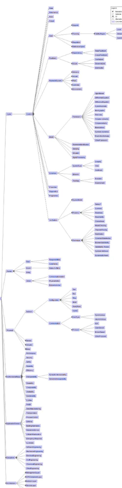
3.1 Feature Model of a CPS representing common and variant properties . . . 18
3.2 Basic concepts of CPS . . . 19
3.3 Layered view for CPS architectures . . . 19
3.4 Overview of the CPS ontology . . . 20
4.1 Overview of the MPM ontology . . . 29
5.1 Overview of the MPM4CPS ontology . . . 40
6.1 Service Component . . . 49
6.2 Overview of the models provided by DEECo and their relations . . . 50
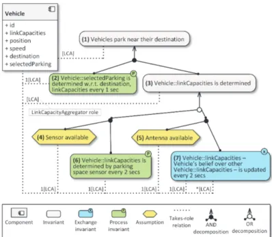
6.3 IRM tree for a smart parking senario . . . 51
6.4 Snippet of jDEECo code . . . 51
6.5 jDEECo runtime framework architecture . . . 52
6.6 An example with an EDL specification . . . 52
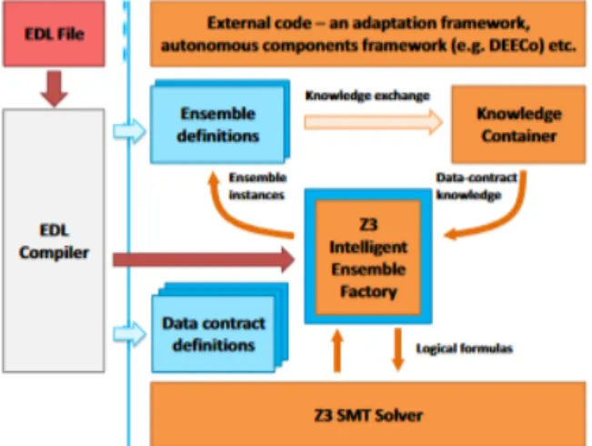
6.7 Framework high-level architecture that supports Ensemble Definition Language (EDL) . . . 52
6.8 Membership vs. boundary conditions in ensemble formation . . . 53
6.9 jDEECo integration with MATSim . . . 54
6.10 jDEECo integration with ROS . . . 54
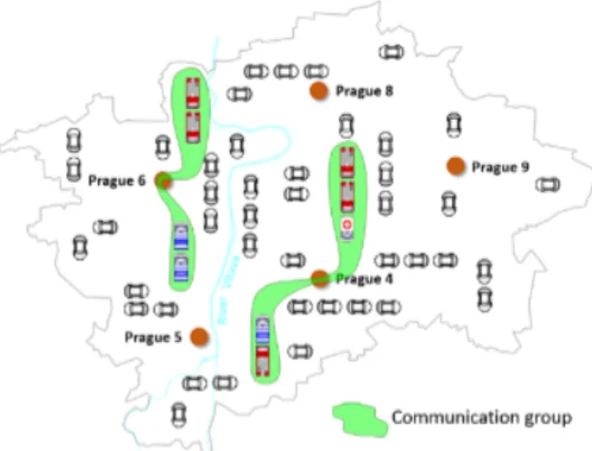
6.11 Illustration of communication groups; each is associated with an instance of SameDestination . . . 54
6.12 Example of two well-chosen emergency groups. . . 55
6.13 Scanning cars (on the right) are sending a photo stream to the edge cloud server reporting spot availability to the parking cars (on the left) . . . 55
6.14 Sample battery energy level during continuous discharge . . . 56
6.15 A visualization of the the area that cleaners should visit and clean . . . 56
6.16 Intelligent production line: home, proximity, and outer zones . . . 57
6.17 Entry for the developer A1 to room W1 is rejected due to the presence of the de-veloper B1 . . . 57
6.18 The use case illustrates a production area, which has many halls. For each hall, there is a single foreman who manages the workers. . . 58
6.19 Models and Tools Transformations and integrations . . . 59
Framework to Relate / Combine Modeling Languages and Techniques
6.21 Overview of the methodology for modeling, verification, and validation
employ-ing simulation and testemploy-ing (see (33)) . . . 63
6.22 Photo of the lab (see (139)) . . . 63
6.23 Structural overview of the employed evaluation scenario (see (139)) . . . 64
6.24 Photo of the employed robots (see (139)) . . . 64
6.25 Overview of the model test in the simulation stage of (33) . . . 65
6.26 Overview of the model in loop simulation in the simulation stage of (33) . . . 65
6.27 Overview of the rapid prototyping in the simulation stage of (33) . . . 66
6.28 Overview of the definition of the software architecture in the prototyping stage of (33) . . . 67
6.29 Overview of the mapping of the architecture to tasks and communication in the prototyping stage of (33) . . . 68
6.30 Overview of software-in-the-loop (sil) simulation in the prototyping stage of (33) 68 6.31 Overview of hardware-in-the-loop (HiL) testing in the prototyping stage of (33) . 69 6.32 Tool landscape and its relation to the development methdology . . . 70
6.33 All MegaModelFragments of theCPSLabMMMegaModel . . . 70
6.34 Overview over the megamodel fragments of the CPSLab megamodel and how the models are related (dashed arrows) . . . 71
6.35 Model Test . . . 73
6.36 Part of the ontology for the MegaModelFragmentCPSLabMTMMFcovering Model Test . . . 73
6.37 Model in the Loop . . . 74
6.38 Part of the ontology for the MegaModelFragment CPSLabMiLMMF covering Model-in-the-Loop (MiL) . . . 75
6.39 Rapid Prototyping (RP) with a detailed robot simulation . . . 75
6.40 Rapid Prototyping (RP) with a remote controlled robot . . . 76
6.41 Part of the ontology for the MegaModelFragment CPSLabRPaMMF covering Rapid Prototyping with Robot Simulation . . . 77
6.42 Part of the ontology for MegaModelFragment CPSLabRPbMMFcovering Rapid Prototyping with Robot Execution . . . 78
6.43 Software in the Loop (SiL) vs. Desktop + Sim . . . 78
6.44 Software in the Loop (SiL) vs. Desktop + Robot . . . 79
6.45 Part of the ontology for the MegaModelFragmentCPSLabSiLaMMFcovering Sil with Simulation . . . 80
6.46 Part of the ontology for the MegaModelFragmentCPSLabSiLbMMFcovering Sil with Execution . . . 81
6.47 Hardware in the Loop (HiL) . . . 82 6.48 Part of the ontology for the MegaModelFragmentCPSLabHiLMMFcovering Hil . 83
1 Introduction
This document reports on the Framework to Relate / Combine Modeling Languages and Tech-niques of Working Group1 on Foundations of the ICT COST Action IC1404 Multi-Paradigm Modelling for Cyber-Physical Systems (MPM4CPS). It first presents an ontology of Cyber Physi-cal Systems in chapter 3 and then an ontology of Multi-Paradigm Modeling in chapter 4. Then, these ontologies are combined to define an ontology of Multi-Paradigm Modeling for Cyber-Physical Systems presented in chapter 5. Finally, a number of megamodel examples are pre-sented in chapter 6 that instantiate the core ontologies and make use of the catalog of languages and tools individuals.
The work of working group 1 on foundations revealed that the dependencies between the framework targeted in this report and the state-of-the-art report in form of deliverable D1.1 (78) was much more tight than initially expected. To avoid capturing some content of the state-of-the-art report also in a redundant form in the ontologies of the framework of this report, it was decided instead to include the relevant information in the ontologies and extract it from there automatically for generating the state-of-the-art report.
Figure 1.1: Overview of the structure of the MPM4CPS ontology
In figure 1.1, the structure of the framework and its elements in form of the different ontologies and its instances is presented.
The first column depicts the framework and its ontologies as presented in this report. This includes the ontology of Cyber-Physical Systems presented in chapter 3, the ontology of Multi-Paradigm Modeling presented in chapter 4 and the combined ontology of Multi-Multi-Paradigm Modeling for Cyber-Physical Systems presented in chapter 5.
The Glossary of Terms for Cyber-Physical Systems presented in the report on the State-of-the-art on Current Formalisms used in Cyber-Physical Systems Development covered by deliver-able D1.1 (78) is extracted automatically from these ontologies and the contained concepts defining the framework.
1. Introduction
In the second column, the catalog of modeling languages and tools that is an instance of the MPM4CPS ontology presented in the report on the State-of-the-art on Current For-malisms used in Cyber-Physical Systems Development covered by deliverable D1.1 (78) is depicted. The catalog of that deliverable will be automatically derived from this instance such that ontology and instances can be kept consistent with only minimal coordination ef-forts.https://www.sharelatex.com/project/5ae2fed74797f945fcb70b13
In the third column, some examples for CPS employing MPM in form of mega models are de-picted that are presented in detail in the Catalog of Megamodel Examples in chapter 6. As shown in the figure, these examples employ the languages and tools listed in the report on the State-of-the-art on Current Formalisms used in Cyber-Physical Systems Development and covered by deliverable D1.1 (78), and also instantiate the MPM4CPS ontology.
1.1 Ontology Development Approach
To define the ontologies of WG1, we have carried out a domain analysis process (97). The do-main analysis process can be defined as the process of identifying, capturing and organizing domain knowledge about the problem domain with the purpose of making it reusable when creating new systems. A domain is usually defined as an area of knowledge or activity charac-terized by a set of concepts and terminology understood by practitioners in that area. In our context, the domains of consideration are the domains of CPS and MPM, and we aim to derive and model the concepts of these domains. Figure 1.2 represents the common structure of do-main analysis methods as it has been derived from survey studies on dodo-main analysis methods. Conventional domain analysis methods consist generally of the activities Domain Scoping and Domain Modeling: Domain Scoping identifies the domains of interest, the stakeholders, and their goals, and defines the scope of the domain. Domain Modeling is the activity for repre-senting the domain, or the domain model. In our study the outputs of the domain modeling process will be the set of ontologies for CPS and MPM as identified by figure 1.1.
The domain model can be represented in different forms such as ontological languages, object-oriented language, algebraic specifications, rules, conceptual models etc. Typically, a domain model is formed through a commonality and variability analysis to concepts in the domain. A domain model is used as a basis for engineering components intended for use in multiple applications within the domain.
One of the popular approaches for domain modeling is feature modeling. A feature is a system property that is relevant to some stakeholder and is used to capture commonalities or discrimi-nate between. A feature model is a model that defines features and their dependencies. Feature models are usually represented in feature diagrams (or tables). A feature diagram is a tree with the root representing a concept (e.g., a software system), and its descendent nodes are features. Relationships between a parent feature and its child features (or sub-features) are categorized as:
• Mandatory - child feature is required. • Optional - child feature is optional.
• Or -at least one of the sub-features must be selected. • Alternative (xor) - one of the sub-features must be selected
A feature configuration is a set of features which describes a member of an SPL. A feature con-straint further restricts the possible selections of features to define configurations. The most common feature constraints are:
Framework to Relate / Combine Modeling Languages and Techniques
Figure 1.2: Common structure of domain analysis methods (adopted from: (131))
• A excludes B - A and B cannot be part of the same product.
Feature modeling is a domain modeling technique, which is widely used to model the com-monality and variability of a particular domain or product family. Another domain modeling technique that is used in software engineering is ontology modeling. A commonly accepted definition of an ontology is “an explicit specification of conceptualization” (84). An ontology represents the semantics of concepts and their relationships using some description language. Basic feature modeling is also a concept description technique that focuses on modeling both the commonality and variability. It has been indicated that feature models can be seen as views on ontologies (54).
To develop the WG1 ontologies presented in details in the following chapters, the aforemen-tioned techniques have been used. For the CPS ontology, feature modeling has been used while for the MPM ontology, modeling with the W3C OWL language and its tool Protege has been used.
2 Ontology of Shared Concepts
As outlined in the introduction of Chapter 1 in Figure 1.1, the structure of the framework and its elements are organized in the form of different ontologies providing classes for the covered domains and individuals (instances) for these classes. The ontology presented in this chapter serves in this context as foundation to define an ontology of Cyber-Physical Systems later in Chapter 3 and an ontology of Multi-Paradigm Modeling in Chapter 4. Then, these ontologies together with the one of this chapter are combined to define an ontology of Multi-Paradigm Modeling for Cyber-Physical Systems presented in Chapter 5.
2.1 Ontology Overview
The shared ontology defines concepts that do not pertain to the CPS and neither to the MPM domain, but that are still required by one of these domains or both. It is a place to define con-cepts reusable by all the ontologies developed in this effort. The class provided in this ontology may be refined to provide extend the definitions to more specific domains.
Figure 2.1 shows an overview of the shared ontology. The details of each concept are provided in the following subsections.
Figure 2.1: Overview of the shared ontology
2.2 DomainConcept
This class groups all concepts of the MPM4CPS ontology. It is further divided into into sub-classed whose names end with DC in order to organize the ontology into sub-domains thus facilitating the navigation across the many concepts of the MPM4CPS ontology. Note that the sub-domain classes are not necessarily disjoints so that a class may belong to several domain concepts.
2.2.1 ParadigmDC (Paradigm Domain Concepts)
This class groups concepts that are related to the paradigm domain. 2.2.1.1 Paradigm
In the usual sense, a paradigm is a set of concepts, patterns, theories, research methods, pos-tulates, and standards that together constitutes a contribution to a domain.
Subclass of
Framework to Relate / Combine Modeling Languages and Techniques
References
• https://en.wikipedia.org/wiki/Paradigm
2.2.1.2 Principle
A principle is a law or rule that has to be, or usually is to be followed, or can be desirably fol-lowed, or is an inevitable consequence of something, such as the laws observed in nature or the way that a system is constructed. The principles of such a system are understood by its users as the essential characteristics of the system, or reflecting system’s designed purpose, and the effective operation or use of which would be impossible if any one of the principles was to be ignored.
Subclass of
• ParadigmDC (see section 2.2.1)
2.2.2 ProcessDC (Process Domain Concepts)
This class groups concepts that are related to the development process domain. 2.2.2.1 Action
This class represents an action performed during an activity. Subclass of
• ProcessDC (see section 2.2.2) 2.2.2.2 Activity
This class represents an activity performed during a process. Subclass of
• ProcessDC (see section 2.2.2) 2.2.2.3 Process
A process is a sequence of activities executed in order to achieve a result or a goal. Subclass of
• ProcessDC (see section 2.2.2) References
• https://en.wikipedia.org/wiki/Process
2.2.2.4 Project Subclass of
• ProcessDC (see section 2.2.2)
2.2.3 RelationDC (Relation Domain Concepts)
This class groups concepts that are related to the relation domain. 2.2.3.1 Constraint
A limitation or a restriction over a relation. Subclass of
2. Ontology of Shared Concepts
2.2.3.2 Relation
Relation or relations may refer to anything that involves communicating with another person, group, society or country.
Subclass of
• RelationDC (see section 2.2.3)
2.2.4 StakeholderDC (Stakeholder Domain Concepts)
This class groups concepts that are related to the stakeholder domain. 2.2.4.1 Concern
In computer science, a concern is a particular set of information that has an effect on the code of a computer program. A concern can be as general as the details of database interaction or as specific as performing a primitive calculation, depending on the level of conversation between developers and the program being discussed. IBM uses the term concern space to describe the sectioning of conceptual information.
Subclass of
• StakeholderDC (see section 2.2.4) 2.2.4.2 ConcernedElement
Subclass of
• StakeholderDC (see section 2.2.4) • ConcernedElement (see section 2.2.4.2) 2.2.4.3 Organization
Subclass of
• StakeholderDC (see section 2.2.4) 2.2.4.4 Purpose
The object for which something exists Subclass of
• StakeholderDC (see section 2.2.4) 2.2.4.5 Role
A role (also role or social role) is a set of connected behaviours, rights, obligations, beliefs, and norms as conceptualized by people in a social situation. It is an expected or free or continu-ously changing behaviour and may have a given individual social status or social position. It is vital to both functionalist and interactionist understandings of society.
Subclass of
• StakeholderDC (see section 2.2.4) 2.2.4.6 Stakeholder
A stakeholder or stakeholders, as defined in its first usage in a 1963 internal memorandum at the Stanford Research Institute, are "those groups without whose support the organization would cease to exist." The theory was later developed and championed by R. Edward Freeman in the 1980s. Since then it has gained wide acceptance in business practice and in theorizing relating to strategic management, corporate governance, business purpose and corporate
so-Framework to Relate / Combine Modeling Languages and Techniques
cial responsibility (CSR). A corporate stakeholder can affect or be affected by the actions of a business as a whole.
Subclass of
• ConcernedElement (see section 2.2.4.2) • StakeholderDC (see section 2.2.4) 2.2.4.7 ToolProvider
Who provides the product and gives the licenses (e.g. company, university, group, ..) Subclass of
• Stakeholder (see section 2.2.4.6) 2.2.5 ToolDC (Tool Domain Concepts)
This class groups concepts that are related to the tool domain. 2.2.5.1 Tool
Set of different tools that are used during system development. Subclass of
• ToolDC (see section 2.2.5) 2.3 Properties
3 Ontology of Cyber-Physical Systems
3.1 State-of-the-art
Cyber-Physical Systems (CPS) are systems that tightly integrate computation with networking and physical processes. Such systems form large networks that communicate with each other and rely on actuators and sensors to monitor and control complex with physical processes, cre-ating complex feedback loops between the physical and the cyber worlds. CPS bring innova-tion in terms of economic and societal impacts for various kinds of industries, creating entirely new markets and platforms for growth. CPS have growing applications in various domains, in-cluding healthcare, transportation, precision agriculture, energy conservation, environmental control, avionics, critical infrastructure control (electric and nuclear power plants, water re-sources, and communications systems), high confidence medical devices and systems, traffic control and safety, advanced automotive systems, process control, distributed robotics (telep-resence, telemedicine), manufacturing, and smart city engineering. The positive economic impact of any one of these applications areas is enormous.
Technically, CPS systems are inherently heterogeneous, typically comprising mechanical, hy-draulic, material, electrical, electronic, and computational components. The engineering pro-cess of CPS requires distinct disciplines to be employed, resulting in a collection of models that are expressed using correspondingly distinct modelling formalisms.
An important realization is that distinct models need to be weaved together consistently to form a complete representation of a system that enables, among other global aspects, perfor-mance analysis, exhaustive simulation and verification, hardware in the loop simulation, deter-mining best overall parameters of the system, prototyping, or implementation. A new frame-work is required that is able to represent these connections between models and, moreover, enable reasoning about them. No single formalism is able to model all aspects of a system; modelling of a CPS system is inherently multi-paradigm, which calls for a trans-disciplinary approach to be able to conjoin abstractions and models from different worlds. Physically, CPS systems are inherently heterogeneous, typically comprising mechanical, hydraulic, material, electrical, electronic, among others. Those areas correspond to engineering disciplines with their own models and abstractions designed to best capture the dynamics of physical pro-cesses (e.g., differential equations, stochastic propro-cesses, etc.). Computationally, CPS systems leverage the half-century old knowledge in computer science and software engineering to es-sentially capture how data is transformed into other useful data, abstracting away from core physical properties occurring in the real world, and particularly the passage of time in physical processes.
The key challenge, as identified a decade ago, is then to provide mathematical and technical foundations to conjoin physical abstractions that describe the dynamics of nature in various engineering domains, as described earlier, with models focusing solely on data transforma-tion. This is necessary to adequately capture and bridge both aspects of a complex, realistic cyber-physical system, and become able to reason and explore system designs collaboratively, allocating responsibilities to software and physical elements, and analyzing trade-offs between them.
Currently, there is a few common design and modelling approaches that allow engineers to handle both aspects of CPS, allowing to bridge the involved disciplines into a shared, common one. Among the existing ones, co-simulation showed that it is possible for computation and physics engineers to cooperate efficiently without enforcing new tools or design methods.
Framework to Relate / Combine Modeling Languages and Techniques
3.2 Ontology Overview
After a domain analysis to CPS we have derived the feature model as shown in figure 3.1. The different components of a CPS system can be designed together or separately: in the latter case, the various different components need to be integrated. A CPS has different component types which can be computational or physical. Furthermore, a CPS has a network which can have different configurations and protocols.
Interoperability relates to how well the different components can operate together. Here we can have syntactic or semantic interoperability. Since both are required in CPS, these two fea-tures are considered mandatory, rather than alternative. Different components in a CPS can be of the same type or of different types, thereby distinguishing between homogeneous or hetero-geneous CPS. The final feature in the feature model presents the various application domains in which CPS can be applied including manufacturing, healthcare, transportation etc.
3.2.1 Ontology Diagram
In this section we describe the metamodel for CPS which represents the concepts and their relations. The metamodel is shown in figure 3.2. A CPS system consists of CPS Components that interact by using one or more Communication Protocols running on a Communication Network. CPS Components interact with other components. A CPS Component is a Compu-tational Component or Physical Component. A compuCompu-tational component is a Software Com-ponent or Hardware ComCom-ponent that can include zero or more Sensors and Actuators. Sensors monitor the Physical Component while Actuators can drive them. Essentially, sensors take a mechanical, optical, magnetic or thermal signal and convert it into voltage and current. This provided data can then be processed and used to define the required action. Both computa-tional components and physical components could have a virtual surrogate. Virtual entities can have different representations such as 3D models, avatars, objects or even a social network account. Some Virtual Entities can also interact with other Virtual Entities to fulfill their goal. 3.2.2 Architecture
The architecture of a CPS represents the gross level structure of the system consisting of cyber-physical components. Current architecture design approaches for CPS seem to be primarily domain-specific and no standard reference architecture has been yet agreed upon. In this line, the development of an ontology for CPS also contributes to the efforts for designing a reference architecture.
A CPS reference architecture defines the generic structure of CPS architectures for particular application domains, laying the foundation for functionality, dependability, and other quality properties. An architecture organizes the functionality and the properties of a system to enable partitioning, verification, and management.
Figure 3.3 presents a layered view of a CPS architecture inspired on the IoT stack that arranges a CPS into successive layers of cohesive modules that share similar concerns. The four layers at the center include device layer, network layer, CPS layer, application layer, and business layer. The CPS component layer includes the capabilities for the CPS components to undertake sens-ing and actuation. The network layer provides functionality for networksens-ing connectivity and transport capabilities enabling the coordination of components. The Services layer consists of functionality for generic support services (such as data processing or data storage), and specific support capabilities for the particular applications that may already apply a degree of intelli-gence. The application layer orchestrates the services to provide emergent properties. Then, there are two main cross-cutting concerns. A Security layer captures the security functional-ity, while the management layer supports capabilities such as device management, traffic and congestion management.
3. Ontology of Cyber-Physical Systems
The reference architecture can be used to derive concrete application architectures. A con-crete architecture defines the boundaries and constraints for the implementation and is used to analyze risks, balance trade-offs, plan the implementation project and allocate tasks. 3.3 Ontology Overview
Figure 3.4 shows an overview of the CPS ontology. The details of each concept are provided in the following subsections.
3.4 Domain Concepts
This ontology of cyber-physical systems contains concepts divided into sub-domains as pre-sented in the following subsections.
3.4.1 ApplicationDomainsDC
Various studies have addressed the domains and domain specific applications of CPS. Gunes et al. summarize a number of research efforts that address some of those domains, namely Smart Manufacturing, Emergency Response, Air Transportation, Critical Infrastructure, Health Care and Medicine, Intelligent Transportation, and Robotic for Service.
3.4.2 ArchitectureDC
3.4.3 QualityRequirementsDC
Cyber-Physical Systems revolutionize our interaction with the physical world. Of course, this revolution does not come free. Since even legacy embedded systems require higher standards than general-purpose computing, we need to pay special attention to this next generation physically-aware engineered system requirements if we really want to put our full trust in them. Therefore, we want to clarify the definitions of some common CPS system-level requirements /challenges.
3.4.3.1 Accuracy
Accuracy refers to the degree of closeness of a system’s measured/observed outcome to its ac-tual/calculated one. A highly accurate system should converge to the actual outcome as close as possible. High accuracy especially comes into play for CPS applications where even small imprecisions are likely to cause system failures. For example, a motion-based object tracking system under the presence of imperfect sensor conditions may take untimely control action based on incorrect object position estimation, which in return leads to the system failure. Subclass of
• Predictability (see section 3.4.3.13) 3.4.3.2 Adaptability
Adaptability refers to the capability of a system to change its state to survive by adjusting its own configuration in response to different circumstances in the environment. A highly adapt-able system should be quickly adaptadapt-able to evolving needs/circumstances. Adaptability is one of the key features in the next generation air transportation systems (e.g. NextGen). NextGen’s capabilities enhance airspace performance with its computerized air transportation network which enables air vehicles immediately to accommodate themselves to evolving operational environment such as weather conditions, air vehicle routing and other pertinent flight trajec-tory patterns over satellites, air traffic congestion, and issues related to security.
Subclass of
Framework to Relate / Combine Modeling Languages and Techniques
3.4.3.3 Availability
Availability refers to the property of a system to be ready for access even when faults occur. A highly available system should isolate malfunctioning portion from itself and continue to oper-ate without it. Malicious cyber-attacks (e.g. denial of service attacks) hinder availability of the system services significantly. For example, in Cyber-Physical Medical Systems, medical data shed light on necessary actions to be taken in a timely manner to save a patient’s life. Mali-cious attacks or system/component failure may cause services providing such data to become unavailable, hence, posing risk on the patient’s life.
Subclass of
• Dependability (see section 3.4.3.7) • Security (see section 3.4.3.20) 3.4.3.4 Composibility
Composibility refers to the property of several components to be merged within a system and their inter-relationships. A highly composable system should allow recombination of the sys-tem components repeatedly to satisfy specific syssys-tem requirements. Composibility should be examined in different levels (e.g. device composibility, code composibility, service composibil-ity, system composibility). Certainly, system composibility is more challenging, hence the need for well-defined composition methodologies that follow composition properties from the bot-tom up. Additionally, requirements and evaluations must be composable accordingly. In the future, it will probably be of paramount importance to incrementally add emerging systems to the system of systems (e.g. CPS) with some predictable confidence without degrading the operation of the resulting system.
Subclass of
• Interoperability (see section 3.4.3.11) 3.4.3.5 Compositonality
Compositionality refers to the property of how well a system can be understood entirely by examining every part of it. A highly compositional system should provide great insight about the whole from derived behaviors of its constituent parts/components. Achieving high com-positionality in CPS design is very challenging especially due to the chaotic behavior of con-stituent physical subsystems. Designing highly compositional CPS involves strong reasoning about the behavior of all constituent cyber and physical subsystems/components and devising cyber-physical methodologies for assembling CPSs from individual cyber and physical compo-nents, while requiring precise property taxonomies, formal metrics and standard test benches for their evaluation, and well-defined mathematical models of the overall system and its con-stituents.
Subclass of
• Predictability (see section 3.4.3.13) 3.4.3.6 Confidentiality
Confidentiality refers to the property of allowing only the authorized parties to access sensi-tive information generated within the system. A highly confidential system should employ the most secure methods of protection from unauthorized access, disclosure, or tampering. Data confidentiality is an important issue that needs to be satisfied in most CPS applications. For example, in an emergency management sensor network, attacks targeting confidentiality of data transmitted may degrade effectiveness of an emergency management system. Confiden-tiality of data transmitted through attacked sensor nodes can be compromised and that can
3. Ontology of Cyber-Physical Systems
cause data flow in the network to be directed over compromised sensors; critical data to be eavesdropped; or fake node identities to be generated in the network. Further, false/malicious data can be injected into the network over those fake nodes. Therefore, confidentiality of data circulation needs to be retained in a reasonable degree.
Subclass of
• Security (see section 3.4.3.20) 3.4.3.7 Dependability
Dependability refers to the property of a system to perform required functionalities during its operation without significant degradation in its performance and outcome. Dependability re-flects the degree of trust put in the whole system. A highly dependable system should operate properly without intrusion, deliver requested services as specified and not fail during its oper-ation. The words dependability and trustworthiness are often used interchangeably. Assuring dependability before actual system operation is a very difficult task to achieve. For example, timing uncertainties regarding sensor readings and prompt actuation may degrade depend-ability and lead to unanticipated consequences. Cyber and physical components of the sys-tem are inherently interdependent and those underlying components might be dynamically interconnected during system operation, which, in return, renders dependability analysis very difficult. A common language to express dependability related information across constituent systems/underlying components should be introduced in the design stage.
Subclass of
• QualityRequirementsDC (see section 3.4.3) 3.4.3.8 Efficiency
Efficiency refers to the amount of resources (such as energy, cost, time etc.) the system requires to deliver specified functionalities. A highly efficient system should operate properly under op-timum amount of system resources. Efficiency is especially important for energy management in CPS applications. For example, smart buildings can detect the absence of occupants and turn off HVAC (Heating, Ventilation, and Air Conditioning) units to save energy. Further, they can provide automated pre-heating or pre-cooling services based on the occupancy prediction techniques.
Subclass of
• Sustainability (see section 3.4.3.21) 3.4.3.9 Heterogeneity
Heterogeneity refers to the property of a system to incorporate a set of different types of inter-acting and interconnected components forming a complex whole. CPSs are inherently hetero-geneous due to constituent physical dynamics, computational elements, control logic, and de-ployment of diverse communication technologies. Therefore, CPSs necessitate heterogeneous composition of all system components. For example, incorporating heterogeneous computing and communication capabilities, future medical devices are likely to be interconnected in in-creasingly complex open systems with a plug-and-play fashion, which makes a heterogeneous control network and closed loop control of interconnected devices crucial. Configuration of such devices may be highly dynamic depending on patient-specific medical considerations. Enabled by the science and emerging technologies, medical systems of the future are expected to provide situation-aware component autonomy, cooperative coordination, real-time guar-antee, and heterogeneous personalized configurations far more capable and complex than to-day’s.
Framework to Relate / Combine Modeling Languages and Techniques
Subclass of
• Interoperability (see section 3.4.3.11) 3.4.3.10 Integrity
Integrity refers to the property of a system to protect itself or information within it from unau-thorized manipulation or modification to preserve correctness of the information. A high integrity system should provide extensive authorization and consistency check mechanisms. High integrity is one of the important properties of a CPS. CPSs need to be developed with greater assurance by providing integrity check mechanisms on several occasions (such as data integrity of network packets, distinguishing malicious behaviors from the ambient noise, iden-tifying false data injection and compromised sensor/actuator components etc.). Properties of the physical and cyber processes should be well-understood and thus can be utilized to define required integrity assurance.
Subclass of
• Security (see section 3.4.3.20) 3.4.3.11 Interoperability
Interoperability refers to the ability of the systems/components to work together, exchange in-formation and use this inin-formation to provide specified services. A highly interoperable system should provide or accept services conducive to effective communication and interoperation among system components. Performing far-reaching battlefield operations and having more interconnected and potentially joint-service combat systems, Unmanned Air Vehicles (UAVs) call for seamless communication between each other and numerous ground vehicles in op-eration. The lack of interoperability standards often causes reduction in the effectiveness of complicated and critical missions. Likewise, according to changing needs, dynamic standards should be developed and tested for devices, systems, and processes used in the Smart Grid to ensure and certify the interoperability of those ones being considered for a specific Smart Grid deployment under realistic operating conditions.
Subclass of
• QualityRequirementsDC (see section 3.4.3) 3.4.3.12 Maintainability
Maintainability refers to the property of a system to be repaired in case a failure occurs. A highly maintainable system should be repaired in a simple and rapid manner at the minimum expenses of supporting resources, and free from causing additional faults during the main-tenance process. With the close interaction among the system components (e.g. sensors, actuators, cyber components, and physical components) underlying CPS infrastructure, au-tonomous predictive /corrective diagnostic mechanisms can be proposed. Continuous moni-toring and testing of the infrastructure can be performed through those mechanisms. The out-come of monitoring and testing facilities help finding which units need to be repaired. Some components, which happen to be the source of recurrent failures, can be redesigned or dis-carded and replaced with the ones with better quality
Subclass of
• Dependability (see section 3.4.3.7) 3.4.3.13 Predictability
Predictability refers to the degree of foreseeing of a system’s state/behavior/functionality ei-ther qualitatively or quantitatively. A highly predicable system should guarantee the
speci-3. Ontology of Cyber-Physical Systems
fied outcome of the system’s behavior/functionality to a great extent every moment of time at which it is operating while meeting all system requirements. In Cyber-Physical Medical Systems (CPMS), smart medical devices together with sophisticated control technologies are supposed to be well adapted to the patient’s conditions, predict the patient’s movements, and change their characteristics based on context awareness within the surrounding environment. Many medical devices perform operations in real-time, satisfying different timing constraints and showing diverse sensitivity to timing uncertainties (e.g. delays, jitters etc.). However, not all components of CPMS are time-predictable. Therefore, in addition to new programming and networking abstractions, new policies of resource allocation and scheduling should be devel-oped to ensure predictable end-to-end timing constraints.
Subclass of
• QualityRequirementsDC (see section 3.4.3) 3.4.3.14 Reconfigurability
Reconfigurability refers to the property of a system to change its configurations in case of failure or upon inner or outer requests. A highly reconfigurable system should be self-configurable, meaning able to fine-tune itself dynamically and coordinate the operation of its components at finer granularities. CPSs can be regarded as autonomously reconfigurable engineered systems. Remote monitoring and control mechanisms might be necessity in some CPS application sce-narios such as international border monitoring, wildfire emergency management, gas pipeline monitoring etc. Operational needs (e.g. security threat level updates, regular code updates, efficient energy management etc.) may change for such scenarios, which calls for significant reconfiguration of sensor/actuator nodes being deployed or the entire network to provide the best possible service and use of resources.
Subclass of
• Sustainability (see section 3.4.3.21) 3.4.3.15 Reliability
Reliability refers to the degree of correctness which a system provides to perform its function. The certification of system capabilities about how to do things correctly does not mean that they are done correctly. So a highly reliable system makes sure that it does the things right. Considering the fact that CPSs are expected to operate reliably in open, evolving, and uncertain environments, uncertainty in the knowledge, attribute (e.g. timing), or outcome of a process in the CPS infrastructure makes it necessary to quantify uncertainties during the CPS design stage. That uncertainty analysis will yield to effective CPS reliability characterization. Besides, accu-racy of physical and cyber components, potential errors in design/control flow, cross-domain network connections in an ad-hoc manner limit the CPS reliability.
Subclass of
• QualityRequirementsDC (see section 3.4.3) 3.4.3.16 Resilience
Resilience refers to the ability of a system to persevere in its operation and delivery of services in an acceptable quality in case the system is exposed to any inner or outer difficulties (e.g. sud-den defect, malfunctioning components, rising workload etc.) that do not exceed its endurance limit. A highly resilient system should be self-healing and comprise early detection and fast recovery mechanisms against failures to continue to meet the demands for services. High re-silience comes into play in delivering mission-critical services (e.g. automated brake control in vehicular CPS, air and oxygen flow control over an automated medical ventilator etc.).
Mission-Framework to Relate / Combine Modeling Languages and Techniques
critical CPS applications are often required to operate even in case of disruptions at any level of the system (e.g. hardware, software, network connections, or the underlying infrastructure). Therefore, designing highly resilient CPS requires thorough understanding of potential failures and disruptions, the resilience properties of the pertinent application, and system evolution due to the dynamically changing nature of the operational environment.
Subclass of
• Sustainability (see section 3.4.3.21) 3.4.3.17 Robustness
Robustness refers to the ability of a system to keep its stable configuration and withstand any failures. A highly robust system should continue to operate in the presence of any failures with-out fundamental changes to its original configuration and prevent those failures from hinder-ing or stopphinder-ing its operation. In addition to failures, the presence of disturbances possibly arising from sensor noises, actuator inaccuracies, faulty communication channels, potential hardware errors or software bugs may degrade overall robustness of CPS. Lack of modeling in-tegrated system dynamics (e.g. actual ambient conditions in which CPSs operate), evolved op-erational environment, or unforeseen events are other particular non-negligible factors, which might be unavoidable in the run-time, hence the need for robust CPS design.
Subclass of
• Reliability (see section 3.4.3.15) 3.4.3.18 Safety
Safety refers to the property of a system to not cause any harm, hazard or risk inside or outside of it during its operation. A very safe system should comply with both general and application-specific safety regulations to a great extent and deploy safety assurance mechanisms in case something went wrong. For example, among the goals for Smart Manufacturing (SM), point-in-time tracking of sustainable production and real-time management of processes through-out the factory yield to improved safety. Safety of manufacturing plants can be highly opti-mized through automated process control using embedded control systems and data collec-tion frameworks (including sensors) across the manufacturing enterprise. Smart networked sensors could detect operational failures/anomalies and help prevention of catastrophic inci-dents due to those failures/anomalies.
Subclass of
• Dependability (see section 3.4.3.7) 3.4.3.19 Scalability
Scalability refers to the ability of a system to keep functioning well even in case of change in its size/increased workload, and take full advantage of it. The increase in the system throughput should be proportional to the increase in the system resources. A highly scalable system should provide scatter and gather mechanisms for workload balancing and effective communication protocols to improve the performance. Depending on their scale, CPSs may comprise over thousands of embedded computers, sensors, and actuators that must work together effectively. Scalable embedded many-core architectures with a programmable interconnect network can be deployed to deliver increasing compute demand in CPS. Further, a high performance and highly scalable infrastructure is needed to allow the entities of CPS to join and leave the existing network dynamically. In the presence of frequent data dissemination among those entities, dynamic software updates (i.e. changing the computer program in run-time) can help update CPS applications dynamically and use CPS resources more productively.
3. Ontology of Cyber-Physical Systems
Subclass of
• Interoperability (see section 3.4.3.11) 3.4.3.20 Security
Security refers to the property of a system to control access to the system resources and tect sensitive information from unauthorized disclosures. A highly secure system should pro-vide protection mechanisms against unauthorized modification of information and unautho-rized withholding of resources, and must be free from disclosure of sensitive information to a great extent. CPSs are vulnerable to failures and attacks on both the physical and cyber sides, due to their scalability, complexity, and dynamic nature. Malicious attacks (e.g. eavesdrop-ping, man-in-the-middle, denial-of-service, injecting fake sensor measurements or actuation requests etc.) can be directed to the cyber infrastructure (e.g. data management layer, commu-nication infrastructure, decision making mechanisms etc.) or the physical components with the intent of disrupting the system in operation or stealing sensitive information. Making use of a large-scale network (such as the Internet), adopting insecure communication protocols, heavy use of legacy systems or rapid adoption of commercial off-the-shelf (COTS) technologies are other factors which make CPSs easily exposed to the security threats.
Subclass of
• QualityRequirementsDC (see section 3.4.3) 3.4.3.21 Sustainability
Sustainability means being capable of enduring without compromising requirements of the system, while renewing the system’s resources and using them efficiently. A highly sustain-able system is a long lasting system which has self-healing and dynamic tuning capabilities under evolving circumstances. Sustainability from energy perspective is an important part of energy provision and management policies. For example, the Smart Grid facilitates energy distribution, management, and customization from the perspective of customers or service providers by incorporating green sources of energy extracted from the physical environment. However, intermittent energy supply and unknown/ill-defined load characterization hinders the efforts to maintain long-term operation of the Smart Grid. To maintain sustainability, the Smart Grid requires planning and operation under uncertainties, use of real-time performance measurements, dynamic optimization techniques for energy usage, environment-aware duty cycling of computing units, and devising self-contained energy distribution facilities (such as autonomous micro grids).
Subclass of
• QualityRequirementsDC (see section 3.4.3) 3.4.4 SystemDC
3.4.4.1 Component Subclass of
• SystemDC (see section 3.4.4) 3.4.4.2 System
Subclass of
• Component (see section 3.4.4.1) • SystemDC (see section 3.4.4)
Framework to Relate / Combine Modeling Languages and Techniques
3.4.4.3 SystemPart Subclass of
• SystemDC (see section 3.4.4) 3.5 Properties
3. Ontology of Cyber-Physical Systems
Framework to Relate / Combine Modeling Languages and Techniques
Figure 3.2: Basic concepts of CPS
3. Ontology of Cyber-Physical Systems
4 Ontology of Multi-Paradigm Modeling
This chapter presents the ontology of Multi-Paradigm Modeling (MPM), which consists of classes and properties to support a classification of MPM approaches. First, a state-of-the-art on MPM focusing on global model management, model integration and multi-formalism mod-elling is presented. Then an overview of the developed MPM ontology is presented followed by a detailed presentation of the proposed classes and properties.
4.1 State-of-the-art
Developing nowadays complex systems with Multi-Paradigm Modeling requires Global Model
Management (GMM) (24; 67) to ensure that the models of different subsystems, of different
views and of different domains are properly combined, even though the models might reside at different levels of abstraction. GMM must also ensure that the development activities that operate on the models are properly coordinated such that the models lead to a proper system as a whole, where the different elements and aspects covered by the different models are correctly integrated and are consistent with each other.
A classification of model integration problems and fundamental integration techniques has been introduced in (79). It highlights the techniques of decomposition and enrichment, which characterize two orthogonal dimensions of development where the system is decomposed into subsystems and domains (horizontal dimension) and into a set of models with increas-ing level of details (vertical dimension). Another approach to support interoperability among languages and tools is presented in (112). The approach is general, however it is exemplified on interoperability among architectural languages and tools (111). An approach to extend ar-chitectural languages is presented in (59). The technique is based on some operators to in-tegrate models and it is generalized in (60). Model integration requires coordinating all activities operating on the models across these dimensions to ensure their consistency. A model-driven approach to automate the propagation of changes among Architecture Descrip-tion Languages (111) is presented in (65). However, inconsistency management goes beyond simply identifying and resolving inconsistencies, since as pointed out in (69), inconsistencies may need to be tolerated at some stage of the development. Therefore, living with inconsis-tencies must be manageable and consequently, an approach is required to detect, resolve, but also tolerate inconsistencies for a significant amount of time during development. The work in (138) provides empirical evidence of how culture, processes, and organization impact trace-ability management and collaboration, and principles support practitioners with collaborative traceability management. The work shows that collaboration and traceability management have the potential to be mutually beneficial - when investing in one, also the other one is posi-tively affected.
The development activities for nowadays complex systems and in particular CPSs encompass multiple domains and teams, with each team using a dedicated set of modelling languages, thus requiring their proper integration and management. Using a single "model-it-all" lan-guage to cover all domains would certainly lead to large, monolithic lanlan-guages that become less efficient, not easily customisable for development environments and tools needed by de-velopment teams, therefore adding difficulties to the already demanding effort of developing CPS. These considerations lead to Multi-Paradigm Modeling (MPM) (135), which advocates the combination of reusable modular modeling languages instead of large monolithic lan-guages. Hence, GMM must support integrating models and modeling languages with appro-priate abstractions and modularity, but also coordinating all activities operating on the models and specified as model operations / transformations. The execution of these model operations
4. Ontology of Multi-Paradigm Modeling
has to be scalable for being able to handle large models. This requires incrementality, where only the operations impacted by a model change are re-executed, thus avoiding the effort to recompute entire models, as in the case of incremental code compilers.
GMM is also known as modeling-in-the-large, which consists of establishing global relation-ships (e.g. model operations that generated one model from other models) between macro-scopic entities (models and meta models), while ignoring the internal details of these enti-ties (24). Mega modeling (25; 67) has been introduced for the purpose of describing these macroscopic entities and their relations. Nowadays only preliminary approaches exist that provide ad-hoc solutions for fragments of the sketched problem and a solid understanding of the underlying needs including new foundations to address this problem as proposed to be developed by WG1 of MPM4CPS. In particular, the current approaches do at most offer some modularity and/or incrementality for a single aspect as modeling languages or model opera-tions. However, support for handling complex modeling landscapes as a whole in a modular and incremental fashion as required for the large-scale problems that exist in practice is not offered so far.
In the following, we will first look at existing solutions that address the construction and exe-cution of models and modeling languages in Section 4.1.1, model operation sin Section 4.1.2, and mega models in Section 4.1.3.
4.1.1 Models and Modeling Languages: Construction and Execution
The construction of models and modeling languages is addressed in the current approaches in three main ways via (1) linking of models and model elements, (2) model interfaces and (3) meta model composition.
4.1.1.1 Model / Model Elements Links
Many approaches rely on traceability links between models and/or model elements to capture megamodelling relations/operations. We adopt here the definition proposed by the Center of Excellence for Software Traceability (CoEST): a trace link is "[...] a specified association between
a pair of artifacts, one comprising the source artifact and one comprising the target artifact...".
The CoEST specialises those links into two dimensions: vertical trace links link [...] artifacts
at different levels of abstraction so as to accommodate lifecycle-wide or end-to-end traceability, such as from requirements to code [...]"; while horizontal trace links associate "[...] artifacts at the same level of abstraction, such as: (i) traces between all the requirements created by ’Mary’, (ii) traces between requirements that are concerned with the performance of the system, or (iii) traces between versions of a particular requirement at different moments in time".
A plethora of approaches have been proposed that make use of trace links for model integration (cf. e.g., (AMW; Epsilon; 68; 109; 87; 129; 31) (MoTE)). The Atlas Model Weaving (AMW) lan-guage (AMW) provided one of the first approaches for capturing hierarchical traceability links between models and model elements. The purpose was to support activities such as automated navigation between elements of the linked models. In this approach, a generic core traceability language is made available and optionally extended to provide semantics specific to the meta-models of the meta-models to be linked. Similarly, the Epsilon framework (Epsilon) provides a tool named ModeLink to establish correspondences between models. MegaL Explorer (68) sup-ports relating heterogeneous software development artifacts using predefined relation types, linking elements that do not necessary have to be models or model elements. SmarfEMF (109) is another tool for linking models based on annotations of Ecore metamodels to specify simple relations between model elements through correspondence rules for attribute values. Com-plex relations are specified with ontologies relating the concepts of the linked languages. The whole set of combined models is converted into Prolog facts to support various activities such
Framework to Relate / Combine Modeling Languages and Techniques
as navigation, consistency and user guidance when editing models. The CONSYSTENT tool and approach (87) make use of a similar idea. However, graph structures and pattern match-ing are used to represent the combined models in a common formalism and to identify and manage inconsistencies instead of Prolog facts as in the case of SmartEMF.
There are also a number of approaches, such as (129) and (31), that build on establishing links between models through the use of integration languages developed for a specific set of inte-grated modeling languages, where the integration language embeds constructs specific to the linked languages. This is also the case for model weaving languages extending the core AMW language. However, AMW has the advantage of capturing the linking domain with a core com-mon language. Other means for linking and integrating models are Triple Graph Grammars (TGG) such as the Model Transformation Engine (MoTE) tool (MoTE), which similarly requires the specification of some sort of integration language (correspondence meta model) specific to the integrated languages. However, an important asset of this approach is that it automati-cally establishes and manages the traceability links and maintains the consistency of the linked models (model synchronization) in a scalable, incremental manner. Finally, in (128; 126)(23), an approach is presented to automatically create and maintain traceability links between mod-els in a scalable manner. While the approach focuses on traceability management rather than model integration, compared to integration languages, it relies on link types defined at the model level (and not at the meta model / language level), thus avoiding the need to update the integration language every time a new language must be integrated.
The comparison of these approaches shows that apart from the approach (128; 126)(23), all approaches suffer from being dependent on the set of integrated languages, thus requiring to better support modularity. Furthermore, only (MoTE)(128; 126)(23) supports automated man-agement of traceability links.
4.1.1.1.1 Interfaces
In addition to links, a few more sophisticated approaches (e.g., (106; 88; 96)) introduce the concept of model interface for specifying how models can be linked. In (106), the Analysis Con-straints Optimization Language (ACOL) is proposed, which has been designed to be pluggable to an Architecture Description Language (ADL). A concept of interface specific to ACOL is in-cluded so that constraints can refer to these interfaces to relate to the model elements expected from the ADL.
SmartEMF (88; SmartEMF) proposes a more generic concept of model interface to track de-pendencies between models and metamodels and provide automated compatibility checks. Composite EMF Models (96; Composite EMF Models) introduces export and import interfaces to specify which model elements of a main model (body) should be exposed to other models (i.e. are part of the public API), and which elements of a body model are to be required from an export interface.
However, these approaches are only preliminary and need to be enriched to cover a larger num-ber of model integration use cases such as for example, specifying modification policies of the linked model elements required to ensure the models can be kept consistent. They also lack integration into GMM.
4.1.1.1.2 Metamodel Composition
Some approaches (e.g., (Kompren; Kompose; 66; EMF Views) (28)) consider the construction of metamodels for expressing views in terms of other metamodels or language fragments. In (66), an approach implemented in the Gaspard2 tool (Gaspard2) is presented where meta models are artificially extended for the purpose of combining independent model transformations re-sulting in an extended transformation for the extended meta models. The work in (60) presents
4. Ontology of Multi-Paradigm Modeling
operators to compose metamodels while preserving specific properties. In (27), the language and tool (Kompren) (Kompren) is proposed to specify and generate slices of metamodels via the selection of classes and properties of an input metamodel. A reduced metamodel is then produced from the input metamodel. However the produced metamodel must be completely regenerated when the input metamodel is changed. Such is the case for the Kompose approach (Kompose), which on the contrary to Kompren, proposes to create compound metamodels, where a set of visible model elements from each combined metamodels is selected, and op-tionally related. The EMF Views (EMF Views; 50) provides similar approach however without the need to duplicate the meta model elements as opposed to Kompose and Kompren where a new metamodel is created. These virtual view metamodels seem to be usable transparently by tools. Finally, the Global Model Management language (GMM*)1(28) provides means to spec-ify and interpret reusable language subsets as sets of constraints combined to form subsetted meta models. Like for EMF Views, these reduced meta models can to some extent be used transparently by tools.
While each of these approaches provides interesting support for modular modeling languages, their unification into a common formalism, the use of an explicit notion of a model interface and their integration into GMM is lacking, except for subsetted metamodels already integrated within the GMM* language.
The execution of integrated models concerns the evaluation of the well-formedness constraints of each combined model alone, but also of the combined models as a whole. To our knowledge, no approach addresses the incremental checking of well-formedness conditions across the dif-ferent language fragments of compound models. However, some approaches on incremental constraints evaluation exist. In (26), changes on models are expressed as sequences of atomic model operations to determine which constraint is impacted by the changes, so that only these constraints need to be re-evaluated. In (EMF-IncQuery; 133), a graph-based query language (EMF-IncQuery) relying on incremental pattern matching for improved performance is also proposed. In (61), an approach is presented for incremental evaluation of constraints based on a scope of model elements referenced by the query and determined during the first query evaluation. This scope is stored into cache and used to determine which queries need to be re-evaluated according for some model changes. In (83), this approach is extended for the case where the constraints themselves may change besides the constrained models. Finally in (43), an incremental OCL checker is presented where a simpler OCL expression and reduced con-text elements set are computed from an OCL constraint and a given structural change event. Evaluating this simpler constraint for the reduced context is sufficient to assert the validity of the initial constraint and requires significantly less computation resources.
4.1.2 Model Operations: Construction and Execution
The construction of model operations is addressed in two ways in the literature. Most ap-proaches combine model operations as model transformations chains (named (1) flow
com-position), where each chained transformation operates at the granularity of complete models.
In order to support reuse and scalability for complex modeling languages, which are defined by composing them from simpler modeling languages, a few approaches have considered spec-ifying model transformations as white boxes. Composed of explicit fine grained operations processing model elements for a given context, these operations are reusable across several model transformations (named (2) context composition).
1We use * to distinguish this existing language and tool from the generic Global Model Management (GMM)