HAL Id: hal-00329198
https://hal.archives-ouvertes.fr/hal-00329198
Submitted on 1 Jan 2001
HAL is a multi-disciplinary open access
archive for the deposit and dissemination of
sci-entific research documents, whether they are
pub-lished or not. The documents may come from
teaching and research institutions in France or
abroad, or from public or private research centers.
L’archive ouverte pluridisciplinaire HAL, est
destinée au dépôt et à la diffusion de documents
scientifiques de niveau recherche, publiés ou non,
émanant des établissements d’enseignement et de
recherche français ou étrangers, des laboratoires
publics ou privés.
field-aligned beam and gyrating ring distributions at the
quasi-perpendicular bow shock with Cluster CIS
E. Möbius, H. Kucharek, C. Mouikis, E. Georgescu, L. M. Kistler, M. A.
Popecki, M. Scholer, J. M. Bosqued, H. Rème, C. W. Carlson, et al.
To cite this version:
E. Möbius, H. Kucharek, C. Mouikis, E. Georgescu, L. M. Kistler, et al.. Observations of the spatial
and temporal structure of field-aligned beam and gyrating ring distributions at the quasi-perpendicular
bow shock with Cluster CIS. Annales Geophysicae, European Geosciences Union, 2001, 19 (10/12),
pp.1411-1420. �hal-00329198�
Annales Geophysicae (2001) 19: 1411–1420 c European Geophysical Society 2001
Annales
Geophysicae
Observations of the spatial and temporal structure of field-aligned
beam and gyrating ring distributions at the quasi-perpendicular
bow shock with Cluster CIS
E. M¨obius1, H. Kucharek2, C. Mouikis1, E. Georgescu2, L. M. Kistler1, M. A. Popecki1, M. Scholer2, J. M. Bosqued3, H. R`eme3, C. W. Carlson5, B. Klecker2, A. Korth6, G. K. Parks5, J. C. Sauvaud3, H. Balsiger4,
M.-B. Bavassano-Cattaneo8, I. Dandouras3, A. M. DiLellis8, L. Eliasson9, V. Formisano8, T. Horbury10, W. Lennartsson7, R. Lundin9, M. McCarthy11, J. P. McFadden5, and G. Paschmann2
1Dept. of Physics and Institute for the Study of Earth, Oceans and Space, University of New Hampshire, Durham, NH, USA 2Max-Planck-Institut f¨ur extraterrestrische Physik, Garching, Germany
3Centre d’Etude Spatiale et Rayonnement, Toulouse, France 4Physikalisches Institut der Universit¨at Bern, Switzerland
5Space Sciences Laboratory, University of California, Berkeley, USA 6Max-Planck-Institut f¨ur Aeronomie, Katlenburg-Lindau, Germany 7Lockheed-Martin Palo Alto Research Laboratory, Palo Alto, USA 8Istituto di Fisica dello Spazio Interplanetario, Rome, Italy 9Institut for Rømdfysik, Kiruna, Sweden
10Imperial College, London, UK
11Space Program, University of Washington, USA
Received: 16 April 2001 – Revised: 29 July 2001 – Accepted: 4 September 2001
Abstract. During the early orbit phase, the Cluster
space-craft have repeatedly crossed the perpendicular Earth’s bow shock and provided the first multi-spacecraft measurements. We have analyzed data from the Cluster Ion Spectrometry experiment (CIS), which observes the 3D-ion distribution function of the major species in the energy range of 5 eV to 40 keV with a 4 s resolution. Beams of reflected ions were observed simultaneously at all spacecraft locations and could be tracked from upstream to the shock itself. They were found to originate from the same distribution of ions that con-stitutes the reflected gyrating ions, which form a ring distri-bution in the velocity space immediately upstream and down-stream of the shock. This observation suggests a common origin of ring and beam populations at quasi-perpendicular shocks in the form of specular reflection and immediate pitch angle scattering. Generally, the spatial evolution across the shock is very similar on all spacecraft, but phased in time according to their relative location. However, a distinct tem-poral structure of the ion fluxes in the field-aligned beam is observed that varies simultaneously on all spacecraft. This is likely to reflect the variations in the reflection and scattering efficiencies.
Key words. Interplanetary physics (planetary bow shocks;
Correspondence to: E. M¨obius
energetic particles; instruments and techniques)
1 Introduction
Early observations of energetic ions upstream of the Earth’s bow shock were reported by Asbridge et al. (1968), Lin et al. (1974) and West and Buck (1976). These observa-tions demonstrated clearly that the Earth’s bow shock is a formidable particle accelerator at our front door step. With its accessibility to a fleet of increasingly sophisticated space-craft, it presents an excellent natural laboratory for the study of collisionless shocks and is a model for even more pow-erful, but much more remote, shock waves in a variety of astrophysical settings. Due to the natural variations in the solar wind and the interplanetary magnetic field (IMF), and in the topology of the Earth’s bow shock, a wide dynamic range of the controlling parameters and different shock orien-tations can be studied during repetitive crossings of the Earth orbiting spacecraft. According to the angle 2BN between
the IMF and the shock normal, shocks are usually separated into two distinct parameter regimes, the quasi-perpendicular shock for 2BN > 45◦ and the quasi-parallel shock for
2BN < 45◦. Associated with these two different
geome-tries observations are two distinct and almost mutually ex-clusive particle populations (e.g. Gosling et al., 1978), which
are referred to as reflected and diffuse components. The re-flected ions form a beam directed along the interplanetary magnetic field; these ions are accelerated in a single reflec-tion off the quasi-perpendicular bow shock (e.g. Paschmann et al., 1980) with their energies rarely exceeding ≈ 10 keV. They are more commonly called field-aligned beams to dis-tinguish themselves from those reflected ions that are vected downstream as gyrating ions with the IMF. In con-trast, diffuse ions upstream of the quasi-parallel shock form a much more isotropic distribution whose energy spectra ex-tend to ≈ 200 keV/e (e.g. Scholer et al., 1979; Ipavich et al., 1981). Conversely, the shock structure itself is quite differ-ent in these two cases. A sharp and stable transition is usu-ally observed at the quasi-perpendicular shock with a distinct step in the magnetic field and often an overshoot, whereas the quasi-parallel shock appears not as steep and is quite variable in space and time.
In the seventies and early eighties, the Earth’s bow shock was primarily described with the tools of an ideal MHD. Par-ticle acceleration was seen as diffusive acceleration due to the compression of the upstream and downstream fluids at the shock (e.g. Axford et al., 1977). A description of the microscopic processes was not available. With a few excep-tions, the observations came from a single satellite and re-quired substantial spatial and time averaging. Over the past decade, the advent of hybrid simulations of the shock and the associated ion distributions has led to a revolution in our un-derstanding of the related micro-physics (e.g. Quest, 1988; Burgess, 1989; Scholer and Terasawa, 1990). It was finally realized that the formation of the energetic particle popula-tions that escape into the upstream environment is intimately linked to the very dissipation processes that are at the heart of the shock formation itself. With the launch of the four Clus-ter satellites, simultaneous observations of fields and par-ticles at four different locations with high time resolution have become available, including the separation of the key species. In addition, the ACE and SOHO spacecraft provide the undisturbed boundary conditions upstream of the shock. Finally, this unique constellation provides a set of tools, with which the shock processes can be studied in the same depth as the detailed modeling is carried out. Anticipated observa-tions and the importance of both the multi-spacecraft obser-vations on varying scales and improved instrumentation have been outlined by M¨obius (1995). The synergism between significantly improved modeling and new experimental tech-niques will allow a much deeper understanding of the cosmic particle accelerator at our front door step.
During the early orbit phase, Cluster primarily encoun-tered a quasi-perpendicular bow shock on the dusk side of the magnetosphere. Therefore, we will limit our prelimi-nary analysis of bow shock related particle distributions to this shock geometry. At the quasi-perpendicular shock, it was recognized earlier than for the parallel shock how inti-mately ion reflection and acceleration is connected with the dissipation of energy at the shock (Paschmann and Sckopke, 1983). At a quasi-perpendicular shock, the compressed in-terplanetary magnetic field forms a barrier for the incoming
solar wind particles. As a consequence of the different gyro-radii of electrons and protons, a repelling electric potential is built up for the protons in the shock layer. A small percent-age of the protons is specularly reflected; they gain energy in the convection electric field of the solar wind and then start to gyrate partly upstream and partly downstream of the shock (Sckopke et al., 1990). Immediately downstream of the shock, a ring distribution is observed in addition to the slowed solar wind. Further downstream, after isotropization and thermalization, the ring merges with the bulk flow. The gyration, thermalization and isotropization of the incoming ions is essential to the formation of the hot magnetosheath flow since it provides the mechanism for the conversion of directed energy into heat. However, in the past, this gyrat-ing rgyrat-ing distribution, which extends to about one gyro radius into the upstream region, has been carefully distinguished from the field-aligned beam distribution (e.g. Formisano, 1985; Gosling and Robson, 1985; Thomsen, 1985). While the specular reflection of the gyrating ring distribution has been explained in a straightforward manner as a reflection in the shock potential, the generation of the beam was not so readily understood. Although kinematics and the energetics of the beams is derived correctly in terms of a reflection along the upstream IMF in the deHofman-Teller frame (Sonnerup, 1969; Paschmann et al., 1980), the microphysics of their gen-eration at the shock has been under debate. As an alternative to reflection leakage from the heated magnetosheath distri-bution has been suggested as the origin of the beams (e.g. Eichler, 1979). Observed distributions that are consistent with this picture, at least for low energy beams, have been observed by Thomsen et al. (1983). However, no general clo-sure on the problem of how to generate the high speed neces-sary for the ions to escape along the field lines, in particular at shocks with 2BN close to 90◦, has been made. Yet the
known effectiveness of quasi-perpendicular shocks to accel-erate particles has triggered further theoretical work on what is referred to as the injection problem at quasi-perpendicular shocks. On the one hand, the work has concentrated on shock surfing to achieve the initial energy, but without redistribu-tion, the resulting ion population is swept downstream (e.g. Lee et al., 1996). On the other hand, the possibility of cross-field diffusion at the shock has been considered in order to provide an avenue for escape (e.g. Giacalone et al., 1994; Scholer et al., 2000).
In this paper, we will make use of the capabilities of the CIS instrument on Cluster to gather the 3D distribution func-tion of ions within one spin period (4 s) with good counting statistics. We will follow the reflected ion populations, both field-aligned beam and gyrating ions, from the upstream re-gion into the quasi-perpendicular shock. In addition, we use multi-spacecraft observations of ions and the magnetic field to unambiguously distinguish intrinsic temporal fluctuations in the ion beam intensity from the effects of the relative mo-tion with respect to the shock. It is demonstrated that both beam and gyrating ions apparently emerge from the same process at the shock, whose effectiveness shows significant temporal variations on the scale of less than one minute.
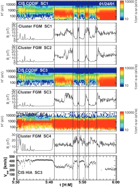
E. M¨obius et al.: Beam and gyrating ring distributions at the bow shock 1413 100 1000 10000 SC1 H + (eV) 100 1000 10000 10 10000 1/cm 2-s-sr-(eV/e) 0 5 10 15 20 25 30 SC1 B (nT) t 0 5 10 15 20 25 30 SC2 B (nT) t 100 1000 10000 SC3 H + (eV) 100 1000 10000 10 10000 1/cm 2-s-sr-(eV/e) 0 5 10 15 20 25 30 SC3 B (nT) t 100 1000 10000 SC4 H + (eV) 100 1000 10000 10 10000 1/cm 2-s-sr-(eV/e) 0 10 20 30 SC4 B (nT) t 0530 0540 0550 0600 0 100 200 300 400 500 SC4 H + V t (km s -1) hhmm 2001 Jan 24 Mon Apr 2 12:57:19 2001 CIS CODIF SC1 Cluster FGM SC1 CIS CODIF SC3 Cluster FGM SC3 CIS CODIF SC4 Cluster FGM SC4 01/24/01 Cluster FGM SC2 0 100 200 300 400 500 5:30 5:40 5:50 6:00 Vsw [km/s] t [H:M] CIS HIA SC3
Fig. 1. From top to bottom: colored spectrogram of the H+differential par-ticle flux and the magnetic field mag-nitude B from spacecraft 1, B from spacecraft 2, H+ and B from space-craft 3 and spacespace-craft 4, followed by the H+bulk speed from spacecraft 3 for the time period of 05:30–06:00 UT on 24 January 2001. The vertical lines indi-cate the bow shock crossings of space-craft 3.
These results may hold the key to the injection problem at quasi-perpendicular shocks, given the opportunity that Clus-ter will provide such comprehensive observations under a va-riety of bow shock conditions.
2 Instrumentation and overview of observations
The Cluster Ion Spectrometry (CIS) instrument consists of two complementary sensors. The Composition and Distri-bution Function (CODIF) analyzer provides the 3D veloc-ity distribution function of the major ion species (H+, He2+, He+and O+) in the energy range from spacecraft potential to 40 keV/e with a time resolution of up to one spin period. The Hot Ion Analyzer (HIA) provides the 3D velocity dis-tribution with high energy and angle resolution, but without species discrimination. Both sensors are based on a top hat electrostatic analyzer design, which provides a 360◦
instan-taneous field-of-view, which is divided into angular pixels. The other direction is covered by making use of the space-craft spin through a sectoring scheme. The energy range is covered by logarithmically stepping the analyzer voltage dur-ing each sector interval. To provide the necessary dynamic range, the entrance aperture of CODIF is divided into two halves, with a difference in the geometric factor of approx-imately two orders of magnitude. The mass per charge of each ion is determined by combining the E/Q measurement from the electrostatic analyzer with the post-acceleration of the ions by up to 20 kV and with a time-of-flight measure-ment. A detailed description of the instruments may be found in R`eme et al. (1997) and M¨obius et al. (1998). The CIS in-struments are operational on spacecraft 1, 3 and 4. On space-craft 2 CIS is disabled due to an apparent failure of its low voltage power converter. An overview of the instrument ca-pabilities and first observations is given in R`eme et al. (2001).
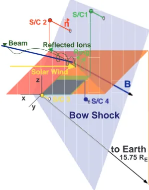
Bow Shock
to Earth
15.75 RE S/C 2 y x z Reflected Ions Beam RingFig. 2. Orientation of the bow shock at the location of the Clus-ter spacecraft and their relative position in space for 24 January 2001. The colored areas and the vertical lines indicate the posi-tion of spacecraft 1, 2 and 4 relative to the reference spacecraft 3. The spatial orien-tation of the vector pointing towards the Earth is shown in a similar way (not to scale). The short lines from the spacecraft towards the shock (light blue shaded area) indicate the relative distance of the three spacecraft from the shock upon their approach.
The magnetic field information is obtained from the Cluster Flux Gate Magnetometers (FGM) (Balogh et al., 1997).
For our analysis of the bow shock, we have chosen one time period during the early operations phase of Cluster in January 2001 with primarily quasi-perpendicular conditions. On 24 January, the Cluster spacecraft remained almost ex-actly at the bow shock for an extended period of time with several consecutive crossings of the spacecraft. During this early orbit phase, Cluster was configured as a regular tetra-hedron with a nominal separation of about 600 km between neighboring spacecraft. Burst mode telemetry was available during the chosen time interval, and the particle distributions could be obtained with the highest resolution of one spin pe-riod.
Figure 1 shows an overview of the temporal evolution as the Cluster spacecraft repeatedly encounter the bow shock during the time interval under investigation (from 05:30 to 06:00 UT on 24 January). Shown are colored spectrograms of the H+population for spacecraft 1, 3 and 4, the magnetic field magnitude for all 4 spacecraft and the H+ bulk speed for spacecraft 3 (the reference spacecraft of the Cluster con-figuration) as a function of time. There is no CIS data from spacecraft 2 due to the failure of the main power supply of CIS on this spacecraft. During the time period of interest,
the spacecraft were transmitting data in burst mode, which provides ion distributions with the highest time resolution of CODIF, i.e. for every spin. CODIF was operated with its high geometric factor side (HS) on spacecraft 1 and 3 and with its low geometric factor side (LS) on spacecraft 4. The H+ bulk speed is taken from HIA on the reference space-craft. Only during the time period of 05:35–05:40 UT were all four spacecraft continuously and simultaneously in the so-lar wind. This can be seen from the narrow maximum of the proton flux below 1 keV, the low and steady magnetic field value and the solar wind speed of 410 km/s. During the first 5 min of the time interval, the spacecraft approached the bow shock several times, indicated by increases in the magnetic field, decreases in the bulk speed and a widening of the H+ energy distributions. Each of the bow shock encounters is also supported by simultaneous magnetic field rotations (not shown here). At 05:41 UT, all four spacecraft cross the bow shock in the sequence spacecraft 4, spacecraft 1, spacecraft 3 and finally spacecraft 2. At 05:47 UT, spacecraft 1, 3 and 2 exit again from the magnetosheath in the reverse sequence and encounter the bow shock an additional three times un-til 06:00 UT in the same sequence, whereas spacecraft 4 re-mains downstream of the bow shock for the rest of this time period. It should be noted that an overshoot of the magnetic field strength over the average downstream value is observed on spacecraft 1, 2 and 4 during the first encounter with the bow shock, but not on spacecraft 3. Generally, there is no sign of upstream energetic particle populations during this time period, except perhaps a small contribution up to a few keV right in front of the bow shock. The general sequence of bow shock crossings for the Cluster spacecraft suggests that the relative speed between the spacecraft and the shock was relatively low during the entire time and that the spacecraft never entered deeply into the magnetosheath.
Figure 2 shows a schematic 3D representation of the lo-cal bow shock geometry and the configuration of the Cluster spacecraft during the time interval of interest. They were at
X =8.2 RE, Y = 10.25 REand Z = 8.75 RE(GSE), i.e. at
a distance of 15.75 REat the dusk flank and over the northern
hemisphere. The interplanetary magnetic field (IMF) pointed earthward at 150◦in azimuth and −20◦in elevation. A mini-mum variance analysis of the magnetic field at the bow shock crossing at 05:41 UT returns an angle of 2Bn−70◦between
the IMF B and the shock normal n. During this time, the bow shock is a very good example for a quasi-perpendicular shock. Under these conditions, a reflected distribution of gy-rating ions is expected at the shock, and a reflected beam into the upstream direction may also develop. Possible trajecto-ries of specularly reflected ions of the incoming solar wind in the pertinent IMF are also shown in Fig. 2. We will use this time interval with the availability of high time resolu-tion data to study the spatial structure of the ion reflecresolu-tion in the shock region and the evolution of the ion distribution, from the upstream region into the shock ramp. Due to the almost erratic motion of the shock across the spacecraft, and its reversal several times in direction, this time period is not suitable to follow the thermalization of the ions downstream
E. M¨obius et al.: Beam and gyrating ring distributions at the bow shock 1415 into the magnetosheath.
3 Observations of reflected ion populations at the shock
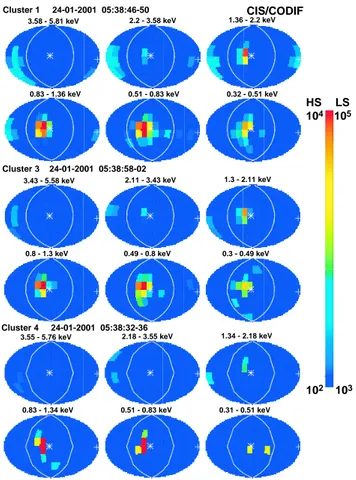
As CODIF provides the full 3D velocity distribution of ions for every spacecraft spin, i.e. every 4 s, the evolution of the ion distribution from the upstream region into the shock can be studied at high time resolution and compared between the different Cluster spacecraft. Figure 3 shows a series of 4π views of angular distributions of the differential H+flux at 6 different energies for spacecraft 1, 3 and 4. Figure 3a shows the distributions upstream of the shock at 05:39 UT, Fig. 3b at the edge of the shock ramp at 5:41 UT, and Fig. 3c just 3 spacecraft spin periods (12 s) further into the shock ramp at 05:41:12 UT. All times are given for the reference spacecraft spacecraft 3. The times for spacecraft 1 and 4 have been chosen such that all views are shown exactly at the ramp edge in Fig. 3b for all 3 spacecraft, as obtained from magnetic field observations. The time separation between the spacecraft has been kept the same for all three figures. The time interval in the ramp (Fig. 3c) has been chosen so that the views from spacecraft 1 and 4 are simultaneous with those at the ramp edge (Fig. 3b) from spacecraft 3 and 1, respectively.
Directional distributions from 0.3 to 6 keV are shown in a globe representation. The individual views are oriented such that sector 0 (out of 16 from the operational mode in use) of the CODIF sectoring scheme with the spacecraft spin is at the left edge of each view. This brings the solar wind flow (coming from GSE-X) two sectors left of the center. To see the views of the low sensitivity side from spacecraft 4 in the same orientation, these views have been rotated by 180◦.
This compensates for instrument viewing in the opposite di-rection. Flows seen at the lower edge of the globes come at 90◦from below and those at the upper edge come from above. Therefore, the intense flux in the center of the view, next to the star representing the magnetic field in the pan-els from 0.3 to 2.0 keV, represents the solar wind. The white star indicates the magnetic field pointing out of the plane of the figure. The solar wind is seen over such a large energy range, due to the high sensitivity of CODIF on its high geo-metric factor side. In fact, the solar wind saturates the sensor. Also found in Fig. 3a is a flux of a much lower intensity gen-erally in the opposite direction of the solar wind and near a 180◦ pitch angle at energies from 0.8 to 6 keV (The white cross indicates the magnetic field pointing into plane of the figure). These ions stream away from the bow shock gener-ally along the magnetic field lines, although the distribution is not exactly centered on the magnetic field direction, indi-cating a visible gyrophase bunching. The beam distribution is only faintly visible on spacecraft 4 because CODIF is op-erated on its low geometric side and thus the count rate is lower by almost two orders of magnitude.
In Figs. 3b and 3c, the solar wind and the beam distribu-tion in the opposite direcdistribu-tion are also visible. However, high particle fluxes are found near a 90◦pitch angle over the same energy range as the beam as well. In fact, the distribution is
Cluster 1 24-01-2001 05:38:46-50
Cluster 3 24-01-2001 05:38:58-02
Cluster 4 24-01-2001 05:38:32-36
3.58 - 5.81 keV 2.2 - 3.58 keV 1.36 - 2.2 keV
0.83 - 1.36 keV 0.51 - 0.83 keV 0.32 - 0.51 keV
3.43 - 5.58 keV 2.11 - 3.43 keV 1.3 - 2.11 keV
0.8 - 1.3 keV 0.49 - 0.8 keV 0.3 - 0.49 keV
3.55 - 5.76 keV 2.18 - 3.55 keV 1.34 - 2.18 keV
0.83 - 1.34 keV 0.51 - 0.83 keV 0.31 - 0.51 keV
CIS/CODIF
HS LS 105 104
102 103
Fig. 3a. 4π angular distributions of the H+fluxes from CODIF in color-coded representation for 6 energies from spacecraft 1 (top), spacecraft 3 (center), and spacecraft 4 (bottom) ≈ 1 min before bow shock entry. Shown is the instrument view of the incoming particle flux. The white star indicates the magnetic field pointing out of the figure and the cross indicates the magnetic field pointing into the figure. The white line indicates a 90◦pitch angle. The scaling of the color bar (in differential flux) is higher by a factor of 10 for the low sensitivity (LS) mode of CODIF on spacecraft 4, because in high sensitivity (HS) mode, the sensor saturates at the lower maximum flux levels chosen for spacecraft 1 and 3.
spread over a wide pitch angle range in the lower left portion of the angular map, with the particles flowing in from below at the lowest energies. With increasing energy, the velocity vector of the maximum flux of this reflected distribution turns more and more to 0◦in elevation. This behaviour is similar on spacecraft 1, 3 and 4. Due to its higher flux than that of the beam, this component is clearly visible on spacecraft 4 in spite of the lower geometric factor.
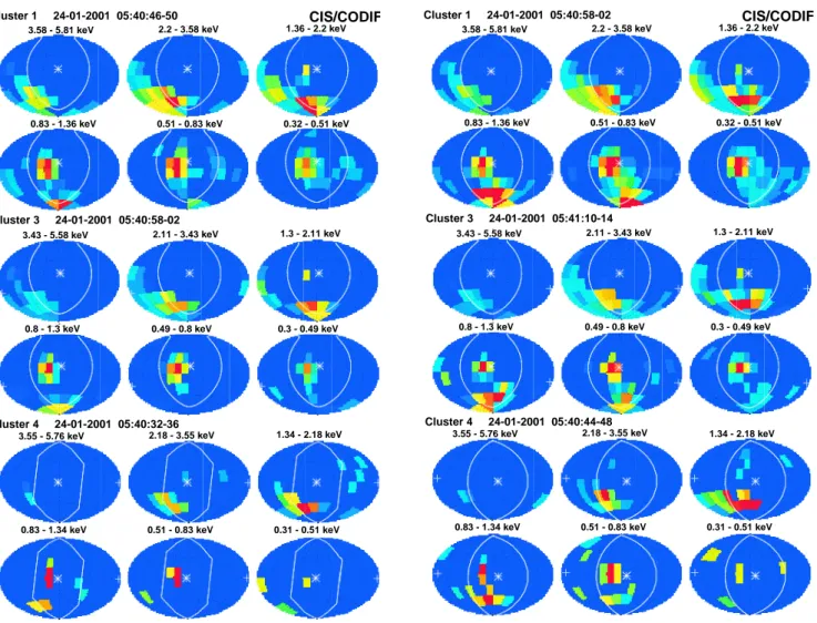
When comparing Figs. 3b and 3c to each other, they ap-pear to be very similar at first glance. However, upon closer inspection, they reveal subtle differences between the two time intervals on the same spacecraft, but not between the in-dividual spacecraft during the same interval. The data were taken only 12 s (3 spin periods) apart. During these 12 s the peak of the reflected distribution moved towards lower pitch angles in the same hemisphere of the solar wind, when the spacecraft are somewhat further into the shock ramp
Cluster 1 24-01-2001 05:40:46-50 Cluster 3 24-01-2001 05:40:58-02 Cluster 4 24-01-2001 05:40:32-36 Cluster 1 2001-01-24 05:40:58-02 Cluster 3 2001-01-24 05:41:10-14 Cluster 4 2001-01-24 05:40:44-48
3.58 - 5.81 keV 2.2 - 3.58 keV 1.36 - 2.2 keV
0.83 - 1.36 keV 0.51 - 0.83 keV 0.32 - 0.51 keV
3.43 - 5.58 keV 2.11 - 3.43 keV 1.3 - 2.11 keV
0.8 - 1.3 keV 0.49 - 0.8 keV 0.3 - 0.49 keV
3.55 - 5.76 keV 2.18 - 3.55 keV 1.34 - 2.18 keV
0.83 - 1.34 keV 0.51 - 0.83 keV 0.31 - 0.51 keV
CIS/CODIF
3.58 - 5.81 keV 2.2 - 3.58 keV 1.36 - 2.2 keV
0.83 - 1.36 keV 0.51 - 0.83 keV 0.32 - 0.51 keV
3.43 - 5.58 keV 2.11 - 3.43 keV 1.3 - 2.11 keV
0.8 - 1.3 keV 0.49 - 0.8 keV 0.3 - 0.49 keV
3.55 - 5.76 keV 2.18 - 3.55 keV 1.34 - 2.18 keV
0.83 - 1.34 keV 0.51 - 0.83 keV 0.31 - 0.51 keV
CIS/CODIF
Fig. 3b. Similar representation as Fig. 3a exactly at the edge of the shock ramp. The fact that no counts are seen in the pole pixels at the bottom for spacecraft 4 is due to the fact that the corresponding angle range is blind at both poles on the low sensitivity side in order to prevent spillover from the high sensitivity side of the sensor.
(Fig. 3c). The peak is found almost exactly at a 90◦pitch an-gle, when the spacecraft are exactly at the edge of the shock ramp (Fig. 3b). This shift of the peak is consistent on all three spacecraft, i.e. they observe exactly the same reflected ion topology, but are time shifted according to their individ-ual arrival times at the shock. Therefore, this observation is consistent with a spatial structure that is coherent over the distance between the three spacecraft.
Over the separation distance of the Cluster spacecraft the reflected ion population appears homogeneous. In addition, the morphology of the shock remains unchanged during the entire observation time period as the shock sweeps repeat-edly across the spacecraft. A persistent observation during this time interval is a reflected ion population that appears in a wide range of pitch angles and is partially swept down-stream with the magnetic field and partially escapes into the upstream region. The most prominent portion of the reflected particles near the 90◦pitch angle is convected downstream
Cluster 1 2001-01-24 05:40:46-50 Cluster 3 2001-01-24 05:40:58-02 Cluster 4 2001-01-24 05:40:32-36 Cluster 1 24-01-2001 05:40:58-02 Cluster 3 24-01-2001 05:41:10-14 Cluster 4 24-01-2001 05:40:44-48
3.58 - 5.81 keV 2.2 - 3.58 keV 1.36 - 2.2 keV
0.83 - 1.36 keV 0.51 - 0.83 keV 0.32 - 0.51 keV
3.43 - 5.58 keV 2.11 - 3.43 keV 1.3 - 2.11 keV
0.8 - 1.3 keV 0.49 - 0.8 keV 0.3 - 0.49 keV
3.55 - 5.76 keV 2.18 - 3.55 keV 1.34 - 2.18 keV
0.83 - 1.34 keV 0.51 - 0.83 keV 0.31 - 0.51 keV CIS/CODIF 3.58 - 5.81 keV 2.2 - 3.58 keV 1.36 - 2.2 keV
0.83 - 1.36 keV 0.51 - 0.83 keV 0.32 - 0.51 keV
3.43 - 5.58 keV 2.11 - 3.43 keV 1.3 - 2.11 keV
0.8 - 1.3 keV 0.49 - 0.8 keV 0.3 - 0.49 keV
3.55 - 5.76 keV 2.18 - 3.55 keV 1.34 - 2.18 keV
0.83 - 1.34 keV 0.51 - 0.83 keV 0.31 - 0.51 keV CIS/CODIF
Fig. 3c. Similar representation as Fig. 3b, 3 spacecraft spin periods later into the shock ramp.
with the IMF and is only visible immediately upstream of the shock. It has disappeared on the view that is taken −1 min before the shock crossing (Fig. 3a). However, a reflected ion beam seems to emerge from the very wide pitch angle dis-tribution of the reflected population that is seen close to the shock at the extreme end of the low pitch angles in the direc-tion opposite to the solar wind. These particles have a high enough velocity component parallel to B in the upstream di-rection so that they can escape against the downstream trans-port with the magnetic field.
Referring to Fig. 2, the shock geometry and the solar wind flow at the northern evening flank conspire so that ions, which are specularly reflected in the shock potential, emerge from the potential generally in the upward (Z) direction and slightly into the Y direction. This direction is consistent with the observed particles seen in the lowest energy panels (0.3– 0.8 keV) in Fig. 3c. The peak of these reflected ions is seen to the lower right of the center in these panels. With re-spect to the magnetic field, their nominal direction is close to the 90◦pitch-angle and slightly into the downstream direc-tion. Thus, all reflected ions should be swept downstream.
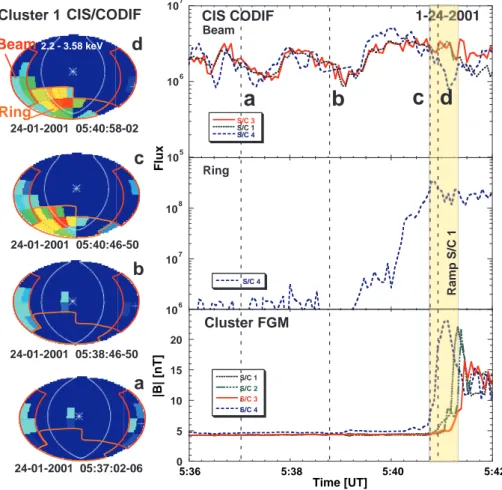
E. M¨obius et al.: Beam and gyrating ring distributions at the bow shock 1417 0 5 10 15 20 25 S/C 1 S/C 2 S/C 3 S/C 4 Cluster FGM 106 107 108 109 S/C 4 Ring 105 106 107 S/C 3 S/C 1 S/C 4 Beam CIS CODIF |B| [nT] 2.2 - 3.58 keV Beam Ring
d
24-01-2001 05:40:58-02c
24-01-2001 05:40:46-50 24-01-2001 05:38:46-50b
24-01-2001 05:37:02-06a
Cluster 1 CIS/CODIF Flux Time [UT] Ramp S/C 1 5:36 5:38 5:40 5:42a
b
c d
Fig. 4. Left column: Angular distributions as seen on spacecraft 1 in the shock ramp (d), at the ramp edge (c), and upstream of the shock (b), (a). The angular regions of the beam (red) and ring (orange) are indicated. Right column: Integrated H+flux in the phase space portions that represent the beam from spacecraft 1, 3 and 4 (upper panel), reflected ring from spacecraft 4 (center panel), and magnetic field strength from all four spacecraft (lower panel). They are shown from approximately 5 min before the bow shock encounter through the shock ramp.
However, from their origin in the shock ramp these ions ap-pear to be spread over a wide pitch angle range, rather than sharply peaked at the specific pitch angle of specular reflec-tion. However, the fluxes vary substantially over the angu-lar range, and only with a very sensitive instrument can the entire distribution be observed. The full distribution thus ap-pears wider than the typical ring and beam distributions pre-viously reported for the quasi-perpendicular bow shock. Ap-parently, both the ring distribution that is ultimately swept downstream and the beam that escapes upstream are inti-mately linked and emerge from the same reflection process. There must be additional scattering processes at work that widen the relatively narrow distribution, as may have been expected from specular reflection in the orderly shock poten-tial of a quasi-perpendicular shock.
In order to illustrate that the ion beam indeed emerges from the combined ring distribution at the shock and to study the spatial and temporal behaviour of these distributions, we have subdivided angular space into a beam and a ring do-main. Figure 4 shows the angular distributions from space-craft 1 in the peak energy region of the ring and beam (2.2– 3.6 keV) for four 4 intervals on the left. In the same
fig-ure, the temporal variation of the beam and ring population fluxes, along with the magnetic field magnitude for all four spacecraft are shown on the right. The beam portion is in-dicated by a red line, and the ring portion is inin-dicated by an orange line in the four angular distributions. We have in-tegrated the ion fluxes separately over these two solid an-gle domains and the full energy range of the beam and ring for spacecraft 1, 3 and 4. The resulting total fluxes for the beam have been compiled as a function of time in the up-per right panel. The center right panel shows the total flux of the ring distribution as obtained on spacecraft 4. We do not show spacecraft 1 and 3 here, because the full ring fluxes saturate CODIF in its high sensitivity mode by about one or-der of magnitude, while the sensor is not saturated in its low sensitivity mode on spacecraft 4. The shaded vertical band indicates the passage of the shock ramp by spacecraft 1, and the magnetic field in the lower right panel shows when each spacecraft reaches the shock. The four time intervals of our angular distributions (a, b, c, and d) are indicated by vertical lines. Panel (a) has been taken almost two minutes further upstream than the view of the beam distribution in Fig. 3a. The other three panels (b, c and d) contain the same time
intervals as shown already in Fig. 3.
The observations presented in Fig. 4 demonstrate quite clearly the value of two substantially different geometric fac-tors in CODIF. While the high sensitivity side of CODIF is saturated by the ring distribution which represents a large fraction of the solar wind flux, the low sensitivity side of CODIF is starved for counts in the beam distribution for the one spin time resolution observations discussed here. With a much higher count rate, the high sensitivity side of CODIF shows remarkable structure and time variation in the beam. For example, in view (a), i.e. substantially further upstream of the shock, the field-aligned beam is more gyrotropic than about two minutes later. Closer to the shock, the beam dis-tribution apparently still has a memory of the original gy-rophase, with which it was injected at the shock. With in-creasing distance this memory subsides because ions with different pitch angle and gyrophase start to mix. In addition, the beam flux varies on the time scale of less than one minute. From downstream of the shock through the shock ramp the flux of the ring distribution (center right panel in Fig. 4) re-mains on a high level and falls off quickly by more than two orders of magnitude with distance from the shock. The ramp location as indicated in the figure is for spacecraft 1 in accor-dance with the angular distributions. Two minutes before the shock crossing, the flux in the ring domain is down to a very low value. The remaining fluxes seen further upstream are on the level of one or a few counts and thus, at the detection threshold for spacecraft 4.
The total flux in the beam distribution is about one order of magnitude lower than that in the ring distribution in the shock ramp, but the flux remains approximately constant (within a factor of three) with distance from the shock. The beam in-deed appears to originate in the combined reflected ion dis-tribution in the shock ramp. It emerges from the edge of this wide pitch angle distribution and then escapes more or less along the field lines under flux conservation. Therefore, the flux in the beam must depend on the angular width of the reflected distribution and on the pitch angle that is achieved after ideal specular reflection in the shock potential. These factors have to be taken into account in addition to the over-all reflection efficiency for solar wind ions.
The beam fluxes on all three spacecraft (spacecraft 1, 3 and 4) track each other almost perfectly. As already discussed above, CODIF on spacecraft 4 has much poorer counting statistics, so that fluctuations around the much smoother spacecraft 1 and 3 observations are found. However, the spacecraft appear to pass a distinct spatial/temporal pattern in the beam distribution, as the fluxes vary distinctly and ex-actly simultaneously on all three spacecraft, with two flux minima at 05:37:30 UT and at 05:39:05 UT. The temporal variation in the beam fluxes appears to be distinctly different from that of the general shock motion, as indicated by the sequence of shock arrival in the magnetic field observations. The exact simultaneous occurence on all three spacecraft ap-parently reflects an intrinsic temporal variation of the beam fluxes as seen by at least three of the Cluster spacecraft. The observed pattern is, therefore, coherent over the spacecraft
separation distance, i.e. 440 km (between spacecraft 3 and 4) to 750 km (between spacecraft 1 and 3), which is of the order of the ion gyro radius of solar wind protons. The unique com-bination of the high time resolution and the multi-spacecraft observations of Cluster make it possible to unambiguously separate the shock motion and this intrinsic variation of the beam.
4 Discussion, conclusions and outlook
We have observed the ion reflection processes at a quasi-perpendicular bow shock during a period when the shock re-peatedly moved across the Cluster formation. The spacecraft remained close to the shock for an extended time, and the shock morphology apparently stayed the same. Generally, also the same particle distributions were observed through-out, although not discussed here in detail. The individual spacecraft passed through the shock structure and the re-flected ion distributions in a consistent sequence, while the shock was moving across. Phase shifted by about 10 s be-tween spacecraft 4 and 1, and by about 12 s bebe-tween space-craft 1 and 3; all three spacespace-craft encountered almost iden-tical angular and energy distributions in the sequence space-craft 4, 1 and 3 during the first shock transition. This indi-cates that a stable pattern of reflected ions is established at the bow shock that is coherent over the spacecraft separation distance and generally does not change substantially during the repeated shock crossings.
A detailed study of the velocity distribution of the re-flected ions during this shock crossing has shown that the ring and beam distributions are intimately connected. The beam distribution that escapes from the shock along the magnetic field lines emerges from the low pitch angle wing of the reflected ring distribution in the shock ramp under flux conservation. When taken in the shock ramp the to-tal flux of the ring distribution as observed on spacecraft 4 varies from 1.1 to 3.3 · 108cm−2s−1 with an average of 1.9 · 108cm−2s−1. The total flux of the beam is, on average, 2.3 · 106cm−2s−1with a minimum of 8.7 · 105cm−2s−1and a maximum of 3.9 · 106cm−2s−1. With a solar wind flux of 9.5·108cm−2s−1, as obtained with CIS HIA, this amounts to a fraction of the solar wind that is reflected in the ring distri-bution of 12–35%, or on average, 20.4%. In the field-aligned beam, about 0.25 ± 0.15% of the solar wind is found. Thus, the flux of the beam is only of the order of 1% of that found in the reflected ring distribution. The observed percentages of the solar wind for the ring and beam distributions agree with values given previously by Sckopke et al. (1990) and Thomsen (1985), respectively.
These results appear generally more consistent with the idea of the ion beam leaking out of a heated distribution downstream of the shock (Eichler, 1979; Thomsen et al., 1983) than a separate direct reflection of these beam ions. However, this would leave a puzzling observation that gen-erally, the thermal distribution in the magnetosheath is not hot enough to account for the observed ion beams. The fact
E. M¨obius et al.: Beam and gyrating ring distributions at the bow shock 1419 that the beam, as observed upstream of the shock, has the
same total flux as the respective pitch angle region of the re-flected ring, suggests a different interpretation. The beam is, in fact, part of the ring distribution itself and is produced by effective pitch angle scattering during or immediately af-ter the reflection, i.e. long before the ring is thermalized in the downstream region. Such a mechanism has recently been suggested in the form of cross-field diffusion at quasi-perpendicular shocks (e.g. Giacalone et al., 1994; Scholer et al., 2000). Simulations of the quasi-perpendicular shock indeed show that a very effective scattering by Alfv´en waves is possible immediately downstream of the ramp (Scholer et al., 2000). Such a mechanism is also consistent with the ob-served fractions in the reflected distributions. Only a small fraction, typically ≈ 1%, of the ring distribution escapes into the upstream region. Future studies of reflected ion distribu-tions as a function of parameters that control the shock, such as fast Mach number, 2BN, and 2BV (the angle with respect
to the solar wind flow), will provide further insight into this important injection problem at quasi-perpendicular shocks.
In general, the flux of the reflected beam is conserved with distance from the shock. However, there is also an apparent intrinsic temporal variation in the fluxes of the field-aligned beam distribution that is seen simultaneously on three space-craft and thus, must reflect a variation in the shock condi-tions. This result leaves the following question: what is the possible reason for the variation of the beam density across different magnetic flux tubes. There are several potential contributors to such a density variation in the beam; the over-all reflection efficiency at the shock, the width of the reflected distribution in pitch angle, i.e. the scattering efficiency, and the nominal pitch angle after specular reflection in relation to
2BN. While we can only speculate about the first two
param-eters, since none of the Cluster spacecraft is actually in the shock ramp during this observation to assess these possibili-ties, we may test the possibility of a change in nominal pitch angle. In fact, the IMF shows moderate excursions in the elevation angle, occuring simultaneously on all spacecraft, when the variations in the beam flux are observed. Since the solar wind ions are reflected into the upward direction by the shock potential, more negative elevation angles would lead to a smaller pitch angle of the reflected ions, which should increase the beam flux. In our case, the variations in mag-netic field elevation do not seem to correlate with the flux variations in the beam. However, the variations in IMF angle could also modify the shock reflection and scattering. At this point, this leaves us with speculative possibilities, and the ex-planation of this observation must await more detailed stud-ies of reflected ion populations at the quasi-perpendicular shock under a variety of different conditions.
The results presented in this paper have clearly demon-strated how valuable the Cluster formation is for the study of complex spatial and time variable structures at the magneto-spheric boundaries. Without the multiple spacecraft configu-ration, it would have been impossible to separate unambigu-ously the intrinsic temporal pattern in the ion beam flux from the repeatedly reversing motion of the bow shock across the
spacecraft. Since both the perpendicular and the quasi-parallel bow shock regions and their complex particle distri-butions are inherently variable in space and time, Cluster and its instrumentation will reveal a number of new phenomena and will probe deeply into the related physical processes. Acknowledgements. We wish to thank the many unnamed individ-uals at the CESR Toulouse, at the University of New Hampshire, at the Max-Planck-Institut f¨ur extraterrestrische Physik, Garching, and f¨ur Aeronomie, Lindau, at the University of California, Berke-ley, at the University of Washington, at IFSI, Frascati, at the Lock-heed Martin Advanced Technology Lab, Palo Alto, at the Institute for Space Physics, Kiruna, and at the Universit¨at Bern for their ded-icated work towards the successful completion of the Cluster CIS experiment for Cluster I and II. This work was supported by CNES, by NASA under Contract NAS5-30613 and Grant NAG5-10131, by ESA under Contract 1501073–2400, by Deutsches Zentrum f¨ur Luft- und Raumfahrt under Contracts 50 OC 8906, 50 OC 89030 and 50 OC 0102, by the Swiss National Science Foundation, and the University of the Kanton Bern. The authors thank M. A. Lee for valuable discussions during the preparation of this paper.
The Editor in Chief thanks S. Bale and another referee for their help in evaluating this paper.
References
Asbridge, J. R., Bame, S. J., and Strong, I. B.: Outward flow of protons from the Earth’s bow shock, J. Geophys. Res., 73, 5777, 1968.
Axford, W. I., Leer, E., and Skadron, G.: The acceleration of cosmic rays by shock waves, Proc. 15th Int. Conf. Cosmic Rays, 11, 132, 1977.
Balogh, A., Dunlop, M. W., Cowley, S. W. H., Southwood, D. J., Thomlinson, J. G., Glassmeier, K. H., Musmann, G., L¨uhr, H., Buchert, S., Acu˜na, M. H., Fairfield, D. H., Slavin, J. A., Riedler, W., Schwingenschuh, K., Kivelson, M. G., and the Clus-ter MagnetomeClus-ter Team: The ClusClus-ter Magnetic Field Investiga-tion, Space Sci. Rev., 79, 65, 1997.
Burgess, D.: Cyclic behaviour at quasi-parallel collisionless shocks, Geophys. Res. Lett., 16, 345, 1989.
Eichler, D.: Particle acceleration in collisionless shocks: Regulated injection and high efficiency, Astrophys. J., 229, 419, 1979. Formisano, V.: Collisionless shock waves in space and in
astro-physics, in: Proc. ESA Workshop on Future Missions in Solar, Heliospheric & Space Plasma Physics, ESA-SP, 235, 83, 1985. Giacalone, J., Jokipii, J. R., and Kota, J.: Ion injection and
accelera-tion at quasi-perpendicular shocks, J. Geophys. Res., 99, 19 351, 1994.
Gosling, J. T., Asbridge, J. R., Bame, J., Paschmann, G., and Sck-opke, N.: Observation of two distinct populations of bow shock ions in the upstream solar wind, Geophys. Res. Lett., 5, 957, 1978.
Gosling, J. T. and Robson, A. E.: Ion reflection, gyration, and dis-sipation at supercritical shocks, in: Collisionless Shocks in the Heliosphere: Reviews of Current Research, (Eds) Tsurutani, B. T. and Stone, R. G., Geophys. Monograph, 35, 141, 1985. Ipavich, F. M., Gloeckler, G., Hamilton, D. C., Kistler, L. M., and
Gosling, J. T.: Protons and alpha particles in field-aligned beams upstream of the bow shock, J. Geophys. Res., 86, 4337, 1981. Lee, M. A., Shapiro, V. D., and Sagdeev, R. Z.: Pickup ion
Lin, R. P., Meng, C. I., and Anderson, K. A.: 30 to 100 keV protons upstream from the Earth’s bow shock, J. Geophys. Res., 79, 489, 1974.
M¨obius, E.: Studies with Cluster upstream and downstream of the bow shock – An experimenter’s perspective, ESA-SP, 371, 127, 1995.
M¨obius, E., Kistler, L. M., Popecki, M., Crocker, K., Granoff, M., Jiang, Y., Sartori, E., Ye, V. R`eme, H., Sauvaud, J. A., Cros, A., Aoustin, C., Camus, T., M´edale, J. L., Rouzaud, J., Carlson, C. W., McFadden, J. P., Curtis, D. W., Heetderks, H., Croyle, J., Ingraham, C., Shelley, E. G., Klumpar, D., Hertzberg, E., Klecker, B., Ertl, M., Eberl, F., K¨astle, H., K¨unneth, E., Laev-erenz, P., Seidenschwang, E., Parks, G. K., McCarthy, M., Ko-rth, A., Gr¨awe, B., Balsiger, H., Schwab, U., and Steinacher, M.: The 3-D plasma distribution function analyzers with time-of-flight mass discrimination for Cluster, FAST and Equator-S, in: Measurement Techniques in Space Plasmas, (Eds) Pfaff, R., Borowski, J., and Young, D., Geophys. Monograph, 102, 243, 1998.
Paschmann, G., Sckopke, N., Asbridge, J. R., Bame S. J., and Gosling, J. T.: Energization of solar wind ions by reflection from the Earth’s bow shock, J. Geophys. Res., 85, 4689, 1980. Paschmann, G. and Sckopke, N.: Ion reflection and heating at the
Earth’s bow shock, in: Topics in Plasma-, Astro- and Space Physics, (Eds) Haerendel, G. and Battrick, B., p. 139, Max-Planck-Institut f¨ur Physik und Astrophysik, Garching, Germany, 1983.
Quest, K. B.: Theory and simulation of collisionless parallel shocks, J. Geophys. Res., 93, 9649, 1988.
R`eme, H., Bosqued, J. M., Sauvaud, J. A., Cros, A., Dandouras, J., Aoustin, C., Martz, Ch., M´edale, J. L., Rouzaud, J., M¨obius, E., Crocker, K., Granoff, M., Kistler, L. M., Hovestadt, D., Klecker, B., Paschmann, G., Ertl, M., K¨unneth, E., Carlson, C. W., Curtis, D. W., Lin, R. P., McFadden, J. P., Croyle, J., Formisano, V., DiLellis, M., Bruno, R., Bavassano-Cattaneo, M. B., Baldetti, B., Chionchio, G., Shelley, E. G., Ghielmetti, A. G., Lennartson, W., Korth, A., Rosenbauer, H., Szemerey, I., Lundin, R., Olson, S., Parks, G. K., McCarthy, M., and Balsiger, H.: The CLUSTER Ion Spectrometry Experiment, Space Sci. Rev., 79, 303, 1997. R`eme, H., Aoustin, J. M., Dandouras, I., Lavraud, B., Sauvaud, J.
A., Barthe, A., Bouyssou, J., Camus, Th., Coeur-Joly, O., Cros, A., Cuvilo, J., Ducay, F., Garbarowitz, Y., Medale, J. L., Penou,
E., Perrier, H., Romefort, D., Rouzaud, J., Alcayde, D., Jacquey, C., Mazelle, C., d’Uston, C., M¨obius, E., Kistler, L. M., Crocker, K., Granoff, M., Moukis, C., Popecki, M., Vosbury, M., Klecker, B., Hovestadt, D., Kucharek, H., K¨unneth, E., Paschmann, G., Scholer, M., Sckopke, N., Carlson, C. W., Curtis, D. W., Ingra-ham, C., Lin, R. P., McFadden, J. P., Parks, G. K., Phan, T., Formisano, V., Amata, E., Bavassano-Cattaneo, M. B., Baldetti, P., Bruno, R., Chioncho, G., DiLellis, A., Marcucci, M. F., Korth, A., Daly, P. W., Graeve, B., Rosenbauer, H., Vasyliunas, V., Mc-Carthy, M., Wilber, M., Eliasson, L., Lundin, R., Olsen, S., Shel-ley, E. G., Fuselier, S., Ghielmetti, A. G., Lennartsson, W., Es-coubet, C. P., Balsiger, H., Friedel, R., Cao, J. B., Kovrazhkin, R. A., Papamastorakis, I., Pellat, R., Scudder, J., and Sonnerup, B.: First identical multispacecraft ion measurements in and near the Earth’s magnetosphere with the Cluster Ion Spectrometry (CIS) experiment, Ann. Geophysicae, this issue (2001).
Scholer, M., Gloeckler, G., Ipavich, F. M., Hovestadt, D., and Klecker, B.: Pitch-angle distributions of energetic protons near the Earth’s bow shock, Geophys. Res. Lett., 6, 707, 1979. Scholer, M. and Terasawa, T.: Ion reflection and dissipation at
quasi-parallel collisionless shocks, Geophys. Res. Lett., 17, 119, 1990.
Scholer, M., Kucharek, H., and Giacalone, J.: Cross-field diffu-sion of charged particles and the problem of ion injection and ac-celeration at quasi-perpendicular shocks, J. Geophys. Res., 105, 18 285, 2000.
Sckopke, N., Paschmann, G., Brinca, A. L., Carlson, C. W., and L¨uhr, H.: Ion thermalization in quasi-perpendicular shocks in-volving reflected ions, J. Geophys. Res., 95, 6337, 1990. Sonnerup, B. U. ¨O.: Acceleration of particles reflected at a shock
front, J. Geophys. Res., 74, 1301, 1969.
Thomsen, M. F., Gosling, J. T., Bame, S. J., Feldman, W. C., Paschmann, G., and Sckopke, N.: Fieled-aligned ion beams up-stream of the earth’s bow shock: Evidence for a magnetosheath source, Geophys. Res. Lett., 10, 1207, 1983.
Thomsen, M. F.: Upstream suprathermal ions, in: Collisionless Shocks in the Heliosphere: Reviews of Current Research, (Eds) Tsurutani, B. T. and Stone, R. G., Geophys. Monograph, 35, 235, 1985.
West, H. I. and Buck, R. M.: Observations of >100 keV protons in the Earth’s magnetosheath, J. Geophys. Res., 81, 569, 1976.