HAL Id: inria-00473393
https://hal.inria.fr/inria-00473393
Submitted on 22 Jan 2019
HAL is a multi-disciplinary open access
archive for the deposit and dissemination of
sci-entific research documents, whether they are
pub-lished or not. The documents may come from
teaching and research institutions in France or
abroad, or from public or private research centers.
L’archive ouverte pluridisciplinaire HAL, est
destinée au dépôt et à la diffusion de documents
scientifiques de niveau recherche, publiés ou non,
émanant des établissements d’enseignement et de
recherche français ou étrangers, des laboratoires
publics ou privés.
A 2-stages locomotion planner for digital actors
Julien Pettré, Jean-Paul Laumond, Thierry Simeon
To cite this version:
Julien Pettré, Jean-Paul Laumond, Thierry Simeon. A 2-stages locomotion planner for digital actors.
ACM SIGGRAPH/Eurographics symposium on Computer animation, Aug 2003, San Diego, United
States. pp.258–264. �inria-00473393�
A 2-Stages Locomotion Planner for Digital Actors
Julien Pettr´e∗
LAAS-CNRS 7, avenue du Colonel Roche 31077 Cedex 4 Toulouse, FRANCE
Jean-Paul Laumond† LAAS-CNRS 7, avenue du Colonel Roche 31077 Cedex 4 Toulouse, FRANCE
Thierry Sim´eon‡ LAAS-CNRS 7, avenue du Colonel Roche 31077 Cedex 4 Toulouse, FRANCE
Abstract
This paper presents a solution to the locomotion planning problem for digital actors. The solution is based both on probabilistic mo-tion planning and on momo-tion capture blending and warping. The paper describes the various components of our solution, from the first path planning to the last animation step. An example illus-trates the progression of the animation construction all along the presentation.
Keywords: motion planning, autonomous characters, probabilistic
roadmaps, obstacle avoidance, locomotion control, motion capture
1
Introduction
Computer animation for digital actors is usually addressed by two research communities along two complementary lines: Computer Graphics community puts emphasis on realism of the motion ren-dering [Earnshaw et al. 1998]. Realism can be obtained by motion imitation thanks to motion capture technologies. More recently, Robotics community tends to provide digital actors with capacity of action planning mainly in the area of motion planning (e.g., [Koga et al. 1994]).
This paper takes advantage of both view points to address virtual human locomotion. It focuses on the following problem: how to automatically compute realistic walking sequences while guaran-teeing 3D obstacle avoidance?
State of the Art An efficient approach consists in splitting the problem into two parts [Kuffner 1998]. From the obstacle avoid-ance geometric point of view the digital actor is bounded by a cylinder. A 2D motion planner automatically computes a collision-free trajectory for the bounding cylinder. Then a motion controller is used to animate the actor along the planned trajectory. Perfor-mances are good enough to address dynamic environments and real time planning.
Locomotion in 3D is investigated in [Shiller et al. 2001]: the workspace is modeled as a multi layered grid. Several types of digital actor bounding boxes are considered according to predefined
∗e-mail: [email protected]
†e-mail:[email protected] ‡e-mail:[email protected]
locomotion behavior (walking, crawling...). Once a path is found in the grid, cyclic motion patterns are used to animate a trajectory along that path. The animation is then modified by dynamic filters to make it consistent.
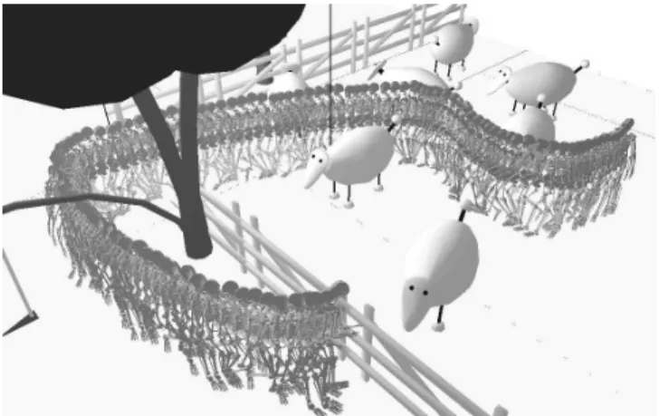
Figure 1: Walking through the sheeps
Other similar approaches combining path planners and motion controllers have been investigated [Raulo et al. 2000; Reynolds 1999; Choi et al. 2003]. None of these approaches addresses the 3D component of the locomotion problem. On one hand, the full integration of the animation process in a planning loop is time con-suming. On the other hand, not considering the animation at the planning stage may lead to use bounding boxes, lowering the real-ism of the followed path (too far from obstacles, or even impossible in the case of narrow passages). Our objective is a realistic loco-motion planner, both considering the quality of the loco-motion and the quality of the followed path. How to reach such an objective with motions as natural as possible?
Architecture The method presented in this paper is an extension of [Kuffner 1998] and a continuation of the works introduced in [Pettr´e et al. n. d.]. It describes successively the main components of our approach. All of them are illustrated with the example pre-sented in Figure 1 where the digital actor is asked to get out of a sheep-fold and to go in front of a wooden barrier, facing a sheep, and to feed it by passing his hand through the wooden barrier. The inputs of the problem are the 3D description of the environment and the two positions of the actor: the initial, standing in the sheep-fold; and the final one: facing the wooden barrier, feeding the sheep. All the bodies in the environment are considered as fixed obstacles to avoid.
The proposed approach is based on two-level modeling of our 57 degrees of freedom (d.o.f.) actor Eugene. Section 2 details the model: the active degrees of freedom gather all the degrees of free-dom attached to the legs. The reactive degrees of freefree-dom gather all the other ones: they are attached to the upper parts of the body;
finally they are labeled with respect of the kinematic chain to which they belong.
A first collision-free path is computed in the 2-dimensional world by using a classical path planner described in Section 3. Then the resulting geometric path is transformed into a trajectory (Section 4). This step, similar to a sampling process, allows to adopt a classical animation data structure: a set of key-frames defin-ing chronologically the successive positions of the actor. Our loco-motion controller described in Section 5. It generates a walking animation from a motion capture data set.
Obstacle avoidance is taken into account at two distinct levels. The first planned path is guaranteed to be collision-free for the lower part of the actor body (i.e. the bodies with active degrees of freedom). Then by applying the motion controller along that path, all the degrees of freedom of the actor are animated. Collision checking is then applied on the whole body. Only the upper parts of the body can be in collision. When collisions occur in subse-quences of the animation, each of these subsesubse-quences is processed with a warping technique presented in Section 6. It slightly modi-fies the predefined animation on the reactive degrees of freedom. In such a way the realism of the original animation is preserved at the best.
Finally, the initial and final positions given as inputs of the whole problem may not be respected due to the modifications to the ani-mation introduced by the warping module. Section 7 shows how to add two planned motions at the beginning and at the end of the animation to the animation in order to respect those positions.
2
Modeling Eugene
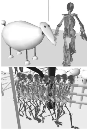
Figure 2: The digital actor: Eugene
Eugene is the name of our digital actor (Figure 2). He is made of 20 rigid bodies and 57 d.o.f. The pelvis is the root of five kinematics chains modeling respectively the arms, the legs and the spine. The pelvis is located in the 3D space with 6 parameters. Its location fixes the location of Eugene in the environment. All the remaining 51 d.o.f. are angular joints.
Two classes of bodies are considered. Pelvis and the legs are responsible for the locomotion. All the 24 corresponding d.o.f. are said to be active d.o.f. The 27 other ones are said to be reactive d.o.f. They deal with the control of the arms and the spine.
Such a classification is based on geometric issues dealing with obstacle avoidance. In the absence of obstacle, the walk controller (Section 5) has in charge to animate all the 51 angular d.o.f. along a given path. Due to the closed kinematic chain constituted by the ground, the legs and the pelvis, any perturbation on the active d.o.f. would affect the position of the pelvis, and then the given path. This is why we want the predefined path guaranteeing collision avoid-ance for all the bodies of the legs. Leg bodies and pelvis are then gathered into a bounding cylinder and the path planner (see below) computes collision-free paths for that cylinder. Possible collisions between obstacles and the upper part of Eugene are processed by
tuning only the reactive d.o.f. without affecting neither the active d.o.f. nor the predefined path. Such a tuning is addressed by the warping module (Section 6).
3
Path Planning
The objective of the Path-Planner module is to find a locomotion path through the environment between two given configurations of the actor. The locomotion path is an evolution of the position of the actor, thus it only deals with the position x, y of the actor and its orientationθ. The path ensures the collision-free motion of the lower part of the body, i.e. of its bounding cylinder.
The principle of this motion planning step is based on proba-bilistic roadmaps [Kavraki et al. 1994]. The main idea of such motion planners is to capture the connectivity of the collision-free configuration space in a roadmap. In our case, nodes are collision-free positions and edges collision-collision-free local paths for the cylinder bounding the lower part of the body. Local paths are Bezier curves of the third degree.
As Eugene is assumed to go only forward, the planner computes a directed roadmap. Once the search is performed we get a first lo-comotion path which is guaranteed to smooth. This first path is then optimized by a classical dichotomy technique maintaining smooth-ness. As a result, the output of this step is a sequence of local paths: a continuous composition of Bezier curves, i.e. a B-Spline.
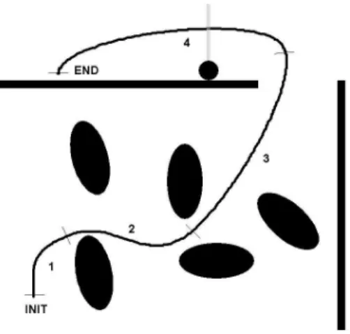
Figure 3: A path made of 4 Bezier curves
Our implementation is based on Move3D the motion planning platform developped a LAAS-CNRS [Sim´eon et al. 2001]. Fig-ure 3 represents the path obtained for the problem illustrated on the Figure 1. The actor first surrounded by sheeps, navigates through them in order to get out of the sheep-fold, then pass under a tree branch to face the wooden barrier, just in front of the sheep.
4
From Path to Trajectory
The module Path-to-Traj transforms the continuous parametric expressions of a 2D path into a discrete set of time stamped posi-tions for the actor along the trajectory, respecting some criteria of maximal velocities and accelerations.
The 2D path is given by the Path-Planner module. It consists in a B-Spline: a continuous sequence of N Bezier curves. Thus, the position P(u) along the path is described by a parametric expression P(u) = [x(u), y(u), θ(u)]T, where u is a real number belonging to
[0, N].
We want to introduce a time parameterization by sampling the path. The time scale defined by ti:0→m= iπwhereπis a constant
number (the sampling period). Thus, we can then get a discrete time parametered expression of P : P(ti) = P(ui)
We may introduce other discrete variables: viandωirespectively
the tangential and the rotational speeds for each time step, with respect P(ui), P(ui−1), andπ. Also, the tangential acceleration
ai(vi,vi−1,π) is defined.
Additive variables are used to account for the following criteria: 1. u0= 0 and um= N,
2. v0= 0 and vm= 0,
3. 0 < vi<Vmax,
4. −Rmax<ωi<Rmax,
5. −Amax<ai<Amax,
6. m is minimal.
where m is the necessary number of time steps to achieve the trajec-tory sampling. Vmax,Rmaxand Amaxare user defined. The sampling
rate, (i.e. the time periodπ) can also be defined.
The transformation of a path into a trajectory respecting veloc-ity and acceleration constraints is a classical problem in Robotics (e.g., [Renaud and Fourquet 1992; Lamiraux and Laumond 1997]). We do not develop the whole procedure.
Figure 4: Characteristic profiles: v,ωand ˙v
Figure 4 illustrates the results of the Path-to-Traj step over the 2D-Path of the Figure 3. The viandωispeed evolutions are
illustrated. The acceleration aiis displayed at the bottom figure.
Note that always one of the previously defined criteria reaches its bound: the solution is optimal.
5
Locomotion Controller
The module Locomotion-Control transforms a set of time pa-rameterized positions into a walk sequence. It is based on a motion capture blending technique. Therefore, it is composed of two ele-ments: a motion capture library and a locomotion controller.
In order to solve a locomotion problem as illustrated on Figure 1, the library is filled with only one type of locomotion: the walk, grouping several similar motion capture examples. The similarity
is estimated with respect of different criteria: same skeleton, same motion structure and same behavior (walking). So the difference between each motion cycle can be summered to the their average (tangential and rotational) speeds( ˜v, ˜ω) .
More precisely motion captures are expressed in the frequency domain using Fourier expansions. [x, y, θ] parameters are
modi-fied as positioning errors around a virtual point moving at( ˜v, ˜ω).
Such a transformation allows to make these parameters cyclic as the rest of the joint angles evolutions. Transformed variables are noted
[∆x,∆y,∆θ].
The input of the locomotion controller is the set of time stamped positions computed by the module Path-to-Traj. Thus, the pa-rameters[P(ti), vi, ωi] of each time step tiare considered. A
mo-tion blending formulæ is computed for each time step, from which a motion cycle is created: MCti. The characteristics speeds ( ˜v, ˜ω)
of MCtiare equal to(vi,ωi).
A single configuration qi is the exctracted from MCti. P(ti) is
considered to project qi on the followed trajectory. Projection is
computed by adding[∆x, ∆y, ∆θ] issued from MCti, to the input
parameters given by P(ti). The other angular values are replaced.
The extraction ensures the continuity of the motion between the frames i and i − 1 and as a result, over the whole trajectory.
Figure 5: Residual collisions
Snapshots of some small parts of the locomotion controller out-put are illustrated on Figure 5. Note that the actor model allow to guarantee collision free motion for the lower part of the body. But some collisions exist between the upper part of the body and the environment. This is illustrated on the two images: between the right hand and the head of a sheep on the top image, and between the head of the actor and a branch on the bottom image.
6
Warping to Avoid
Figure 6: Warping method steps
The goal of the Warping module is to locally modify the animation of the upper bodies of Eugene (arms and spine) when collision occur in the animation produced by the module
Locomotion-Control. At this stage, the animation is a sequence
of keyframes which a complete specification of all the 57 d.o.f. Each key-frame of the sequence is scanned and a collision test is performed. At this level only the bodies of the upper part of Eugene may be in collision. Leg bodies as well as pelvis are necessarily collision-free. If a collision exists, the frame is marked with a label (left-arm, right-arm or head-spine) according to the body involving a collision with the obstacles. All the marked frames are gathered into connected subsequences. Subsequences are extended to create blocks absorbing collision-free frames in the neighborhood of the colliding subsequences (Figure 6-a). Such a subsequence exten-sion is considered to provide smooth motions able to anticipate the corrective actions to be done. Each connected frame block is then processed independently.
Let us consider the example of a block with a left-arm label. The method consists in choosing a set of d.o.f. of the left arm at random until the left arm do not collide anymore. A new collision-free frame block is then created for which the d.o.f. of the left arm are modified using this set of values (Figure 6-b).
Now we apply a warping procedure considering the two blocks: the original and the modified one. Such a procedure aiming at modifying a sequence of key-frames is a classical one in graph-ics [Witkin and Popovic 1995]. By construction the two blocks have the same number of keyframes. The warping procedure consists in interpolating the reactive d.o.f. of the left arm. The parameters of the interpolation are controlled by the collision-checker in order to provide a new configuration for the left arm which is as close as possible from the original configuration while being collision-free (Figure 6-c).
Figure 7 illustrates the result of the warping module, over the two parts illustrated in Figure 5 (output of the
Locomotion-Control). Note that the realism of the motion is
preserved, and that the movement allowing to avoid the collision is quite minimal.
Figure 7: Avoided branch and sheep
7
Initial and Final Positioning
Our walk controller has a specificity: it respects strictly the initial and the final configurations given as inputs of the problem. This means that while starting or ending the locomotion, the actor pro-gressively adopt those configurations.
Remember that in the case of Figure 1, the actor is asked to feed the virtual sheep. For that its hand must go on the other side of the barrier. When the walk controller is applied, the final position (where the actor feeds the sheep) is respected but some collisions exist. Then collisions are avoided by applying the warping module. This leads to modify the motion of the arm. As it concerns the last frames in the animation, the final position is affected: the hand stays away from the barrier, and the actor cannot feed the sheep anymore: see the middle image of the Figure 8.
In order to still reach the final position, a single query probabilis-tic motion planner [Kuffner and LaValle 2000] is used between the last modified configuration and the final (and desired) configura-tion. The result is then sampled and added at the end of the anima-tion. The additive frames are illustrated on the bottom image of the Figure 8.
8
Discussion
The whole number of key-frames generated by the example of Fig-ure 1 is: 331. Computing times consumed on this example are distributed as follow1:
1. Path search: 0.84 s (with a precomputed roadmap),
1Implementation has been done within Move3D platform [Sim´eon et al. 2001]. We used a Sun Blade 100 (proc. UltraSPARC-IIe 500 MHz, 768 Mo RAM)
Figure 8: Feeding a sheep
2. Path optimization: 3. s, 3. Path to trajectory: 0.9 s, 4. Locomotion controller: 0.3 s,
5. Warping: 0.74 s + 0.87 s (collisions identification and their
solution + warping itself), 6. Initial and final positioning: 0.98 s,
Note that computing times seem high, even if the machine used is weak. An effort is currently done to decrease the Path optimiza-tion computing times. Indeed, We use a generic and classical di-chotomic method to optimize our path. The steering method for digital actors is quite particular, and should be optimized in a differ-ent manner. Also note that this is a developmdiffer-ent and non-optimized code.
More generally, computing times are sensitive to several ele-ments. First, the complexity of the environment. The use of pre-computed roadmaps allow to preserve the performance of the path search in the query phase. Nevertheless, environment complexity extends the time necessary to solve collisions in the warping mod-ule and to plan motions in the last positioning modmod-ule.
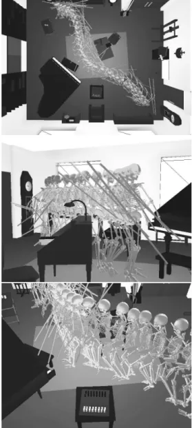
The Figure 9 illustrates a more complex environment: a living room. To increase the complexity of the locomotion task, we added a long bar in the right hand of Eugene. This version of the model is named CWTB-Eugene (Careful with that bar Eugene [Waters et al. 1969]). So the problem for CWTB-Eugene is now to handle a bar while crossing the living room. In order to avoid the desk, the piano and other furniture, CWTB-Eugene carries the bar in front of him. Different views appear in Figure 9.
Figure 9: Back home
Time consumed by the PathToTra module depends on the user limits given. The more severe they are, the more this module is consuming. Also, the total number of frame is critical. Indeed, the
Warping module will test the collision existence for each frame.
Over more simple problems, such as illustrated on Figure 10, the whole result is obtained in less than a second.
9
Conclusion
We have presented a solution for digital actors locomotion prob-lems. This paper insists on the modularity of the approach. Each component can be modified or replaced with ease. The example de-tailed along the paper illustrates the role of each component through the locomotion planning process and demonstrates the realism of the result.
Accounting for the 3D model of the environment is a specificity of our solution. Through our results, the navigation close to ob-stacles and their avoidance, thanks to little movements of the upper body, gives an illusion of a real interaction between the digital actor
Figure 10: Skinning Eugene
and the digital environment.
Our locomotion planner is still to be enhanced: we want to in-troduce the ability for the digital actor to change its locomotion behavior: by crouching, crawling, etc. This objective raises some new needs for our solution: the extension of the content of our mo-tion library, the introducmo-tion of rules to change from a behavior to another. Some approaches of those problems exist in the litera-ture. But a main part of our architecture is already designed to deal with such problems. Those enhancements are planned in our future works. Finally the scope of the approach at its current stage is re-stricted to walking tasks on flat floor. Future works will integrate rough terrains as well as stairs.
Acknowledgement: The environment of the living room in the examples shown in Figure 9 and 10 have been provided by Daesign.
References
CHOI, M. G., LEE, J.,ANDSHIN, S. Y. 2003. Planning biped lo-comotion using motion capture data and probabilistic roadmaps.
ACM transactions on Graphics, Vol. 22(2).
EARNSHAW, R., MAGNETAT-THALMANN, N., TERZOPOULOS,
D.,ANDTHALMANN, D. 1998. Computer animation for virtual humans. IEEE Computer Graphics and Applications (Septem-ber/October), 20–23.
KAVRAKI, L., SVESTKA, P., LATOMBE, J.-C.,ANDOVERMARS, M. 1994. Probabilistic roadmaps for path planning in high-dimensional configuration spaces. Tech. Rep. CS-TR-94-1519. KOGA, Y., KONDO, K., KUFFNER, J., AND LATOMBE, J.-C.
1994. Planning motions with intentions. Computer Graphics
vol. 28, Annual Conference Series, 395–408.
KUFFNER, J., ANDLAVALLE, S. 2000. Rrt-connect : An ef-ficient approach to single-query path planning. IEEE
Interna-tional Conference on Robotics and Automation.
KUFFNER, J. 1998. Goal-directed navigation for animated char-acters using real-time path planning and control. CAPTECH, 171–186.
LAMIRAUX, F.,ANDLAUMOND, J.-P. 1997. From paths to tra-jectories for multi-body mobile robots. 5th International
Sym-posium on Experimental Robotics (ISER’97), Barcelona, June 1997, pp.237-245..
PETTRE´, J., SIMEON´ , T.,ANDLAUMOND, J. P. Planning human walk in virtual environments. Proc. IEEE/RSJ Int. Conf. on
In-telligent Robots and Systems (IROS’02).
RAULO, D., AHUACTZIN, J.,ANDLAUGIER, C. 2000. Control-ling virtual autonomous entities in dynamic environments using an appropriate sense-plan-control paradigm. Proc. of the 2000
IEEE/RS. International Conference on Intelligent Robots and Systems.
RENAUD, M.,ANDFOURQUET, J. 1992. Time-optimal motions of robot manipulators including dynamics. The Robotics Review
n. 2.
REYNOLDS, C. W. 1999. Steering behaviors for autonomous char-acters. Proceedings of 1999 Game Developers Conference. SHILLER, Z., YAMANE, K.,ANDNAKAMURA, Y. 2001. Planning
motion patterns of human figures using a multi-layered grid and the dynamics filter. IEEE Int. Conf. on Robotics and Automation. SIMEON´ , T., LAUMOND, J.,ANDLAMIRAUX., F. 2001. Move3d: a generic platform for motion planning. 4th Internation
Sympo-sium on Assembly and Task Planning, Japan..
WATERS, R., WRIGHT, R., MASON, N., AND GILMOUR, D.
1969. Careful with that axe, eugene. Pink Floyd – Ummagumma. WITKIN, A., ANDPOPOVIC, Z. 1995. Motion warping. Proc.