International Symposium on Mechatronics and Renewable Energies (ISMRE'2018), El-Oued, Algeria, December 10-11, 2018
An automatic EMI filter design and optimization for
photovoltaic inverter
1* F. BEGGAT, 2* F. BOUCHAFAA, 3* K. MILOUDI
*
Electronic Instrumentation Laboratory.
University of Science and Technology Houari Boumediene BP 32 EL ALIA 16111 BAB EZZOUAR ALGER.
Abstract—Electromagnetic interference (EMI) issue has become one of the extremely important problems to be solved in the photovoltaic (PV) inverter system. It is well known that the static converters used in PV system are major sources of conducted disturbances which are the common mode and differential mode. Often, the solution used to reduce conducted emissions consists to use the EMI filters. In this paper, a complete computer aided procedure based on a co-simulation Matlab and LT-Spice. A Database representing the parasitic elements of the passive component, this last one allowed feed the program of design of the filter under Matlab. Finally, the final phase allowed to validate the filter performance with a temporal solver or / and frequency under LT-Spice. Simulation and experimental results give a firm support to the proposed method.
Keywords—Electromagnetic interference, automatic design, EMI filter, PV inverter, parasitic elements.
I. INTRODUCTION
Solar energy, as a kind of clean and renewable energy sources, has become increasingly widely used in people's daily lives. The main components are composed of photovoltaic panels, inverters, and the electrical power protection appropriate to the size of the photovoltaic systems [2]. The inverter is a device used to convert direct current from the photovoltaic panels into alternating current [1]. EMI can be caused in the photovoltaic system due to the high switching frequency of the inverter and also the parasitic elements existing in the whole system [4]. The high dv/dt and high di/dt will certainly generate common mode (CM) current and differential mode (DM) voltage, respectively. Thus, the electromagnetic compatibility (EMC) is an important topic that should be focused on photovoltaic systems [1-2]. The method to overcome this problem can be classified into three groups. The first one is to change the inverter topologies . The second is to improve the control strategies [11]. And the third one is to insert EMI filter.
EMI filter is a device used to mitigate the conducted EMI in any electrical/electronic systems. There are several types, for example, passive EMI filter, active EMI filter, and hybrid EMI filter. Each model has advantages and disadvantages. In this paper, we will use passive EMI filter to solve the EMI problem. This filter is simple to design and used widely for popular applications, and there are some studies and research designing of filter [9-10] to provide all the electrical devices according to the standard.
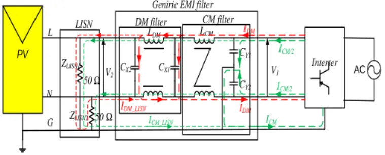
Figure 1 presents the structure of passive EMI filter for photovoltaic system. It contains main components which are
one CM inductor (LCM),two DM inductors (LDM), two CM capacitors (CCM), and two DM capacitors (CDM), EMI from power converters is often measured using a standard line impedance stabilization network (LISN) at the input side [8].
L N G ZLISN1 50 Ω Interter LCM LDM CY1 CY2 CX2 CX1 ZLISN2 50 Ω IDM ICM/2 ICM/2 ICM IDM CM filter DM filter
Geniric EMI filter LISN ICM_LISN IDM_LISN V1 V2 PV AC
Fig.1 . Structure of Geniric EMI filter for photovoltaic system.
Many works have been conducted on designing of filter. Reference [10] proposed method is able an automatically determining the filter topology, filter order, and filter components values simultaneously.
Another issue in filter design is the parasitic components and non-ideal characteristic of filter elements. It could be considered when the filter had been designed and realized by adjusting elements values and filter layout [3]. Another approach assumed that the high frequency attenuation was determined by parasitic components. The filter lowest corner frequency was used to calculate the main inductors and capacitors values, while the highest one was to compute the limitation of the parasitic components. Reference [9] proposed an automatic design for Power Electronic Converters based algorithm and on databases of magnetic cores, capacitors.
However, in designing of an EMI filter, the traditional parameters of a PV inverter system are not precise enough, which eventually leads that the filtering effect cannot achieve the desired results. In reference [2] proposed design for PV system take into consider the influences of PV array parameters.
In this paper, an EMI filter design for photovoltaic system is treated as an optimization problem with the minimization of filter volume and increases the accuracy of filter attenuation as the optimization goal, and take into consider the influences of PV array parameters, DC side cable impedance, inverter parasitic capacitance, the parasitic elements and non-ideal characteristics of filter. In order to
determine the topology, elements values of the filter, an automatically determining high performing EMI filters.
II. EMI FILTER DESIGN PROCESURE
The proposed design procedure is a decide based algorithm that takes into account the characteristics of the filter application: PV array’s parasitic parameters, the power electronic circuits, the constraints of the filter design, and the databases of commercial components for the setup of the EMI filters.
A. Components databases
The flowchart of the design method is shown in Figure 2, Firstly, the databases core is the geometrical parameters: inside diameters (Dint) and outside (Dout), height (Hcore) , maximum number of turns (Nmax) and the conducting wire diameter (Dwire) [3].
The databases capacitance is the parasitic parameters of filter’s capacitors CX, CY : the Equivalent Series Resistance (ESR), the Equivalent Series inductance (ESL) , capacitors (C) and the capacitor volume (VC) [12].
Input Data
· ICM and IDM
· ICM_max and IDM_max
· VCM and VDM · EMC Standards(EN5011 standard) · Zpv and Zinverter · n phase Components Databases · Core Database ( FT50-61,FT37-43…. )
· Conducting wires Databases
· Cx and Cy Capacitors Databases (Metallized polyester film capacitors)
Select Ferrite Core Select Filter
Topology
Compute the cutoff foCM , foDM
Compute LCM and LDM Select Cx, Cy
Compute the required corner frequency
Compute the cutoff fch CM, fch DM Compute ESLmax Cpmax ESL< ESLmax Cp< Cpmax Compute Nmax Compute parasitic elements Cp and RL Validate filter performance Sum Volumes and Accuracy Minimize objective functions best design output data NO YES
Fig.2 Flowchart of the proposed design method.
B. Input Data
Secondly, the designer must define the following Input Data:
· ICM, IDM: the common mode and differential mode currents are measured using current probes on the
PV inverter wires between the LISN and the converter [2].
· ICM_max , IDM_max : maximum value of the CM and DM currents; are taken into consideration to define the capacitance value.
· IMC_EMC , IDM_EMC : the limit CM and DM currents given by the EMC standards (EN55022 Class B standard)[3].
· ZPV: the parasitic capacitances between the photovoltaic cells and the ground (Cpv1, CPV), parasitic inductances of the cable ( LPV1, LPV ) [2].
· ZLISN : the impedance of the line impedance stabilization network .
· VCM, VDM : the voltage source are the equivalent CM and DM interference source.
· Zpath: the propagation path impedance of both sides EMI filtering [12].
C. Filter Optimization
In this section, the EMI filter for pv systems sized to meet the EN55022 standard[1]. The objective functions are the volume and accuracy of filter attenuation. The design constraints, the maximum CM and DM voltage in the converter according to EN55022, the minimum attenuation of the EMI filter in the filtered frequency band.
The optimization problem is illustrated as follows [7]:
, , 1 1 i LCM LDMi i n n filter Cy Cxi i i
Vol
Vol
Vol
(1)
1
n obtained i required i iAtt
f
Att
f
f
N
(2) filterVol
,
Vol
LCM,LDM andVol
Cy C, x sont le volume defiltre, inductances et les condensateurs.
Constraints and objective functions will be explained in the following paragraphs.
a) Inductors volume expressions
The inductances of the filter are made in toroidal shapes with the parameters described in Fig.3. The Magnetic material used will be ferrite [13].
The total volume (V) of the coil taking into account the windings is then expressed according to Dint, Dout, and Hcore [10]:
2
2
2.
L out cond core cond
Vol
D
D
H
D
(3)The value of the LCM inductance equ 04 depends on the geometrical characteristics of the core (Ae the core section equ (4), Lmagnetic the length of the magnetic path equ (5) ) and the number of turns N by
winding[13].
int
1 2 e core out A H D D (4)
int
2
magnetic outL
D
D
(5) 2 2 0 int 0 int e r core out CM r CM magnetic out A N H D D L N L L D D (6)The method of winding wire turns on a cylindrical form introduces the resistance of the wire (RL), the resistance (Rp) representing the losses of magnetic materials, as well as the parasitic capacitance (Cp) between the neighboring turns.
A realistic model for a coil has a resistance in parallel (Rp) and resistance series (RL) with an inductance (L), all in parallel with a capacitance (CP). [3]
Fig.4 Equivalent model of coupled inductance [6]. The copper losses are estimated using the serial resistance Rs of the inductor given by Eq(7).
int
8
core out L condH
D
D
N
R
D
(7)The intra-winding capacitance of inductor (Epc i Fig.3) induces mainly resonances in high frequency range and reduces the effectiveness of the EMI filter. It is essential to estimate its value. The latter is computed by using Eq(8) [3-6]
0 int 1 2 2. . 1 2. .r out core wire
p wire D D H D N N C C C N D
(8)C1, C2 are respectively the inner and outside circumferences.
b) Capacitors volume expressions
The capacitors mainly used in EMI applications: the MKP-type (polypropylene Cx) for the filtering of the differential mode noise and the MKT-type (polyester Cy) for the common mode noise. The volume of the capacitors has been fitted to datasheets [12].
The equivalent circuit of capacitors of EMI filters is the series connections of: resistance ESR, which represents the losses of the capacitor, inductance ESL, which represents inductance of the capacitor and the actual capacitance C of the capacitor [6]. Fig.5 .
Fig.5 Electrical model of a capacitor. The parameters of filter’s capacitors CX, CY equivalent circuits are calculated basing on the modulus of impedance characteristics, which were measured by impedance analyzer Agilent 4294A [12].
D. Optimization Algorithm Applied
The deterministic algorithm that uses gradients, in this case SQP (Sequential Quadratic Programming) is utilized to solve the optimization problem. SQP methods solve a sequence of optimization sub problems, each of which optimizes a quadratic model of the objective subject to a linearization of the constraints. SQP methods have been implemented such well known numerical environments as MATLAB. There also exist numerous software libraries, including open source. The detail of the optimization algorithm is as follows [5-7].
1) Step 1: Initial values selection
The choice of the initial solution of the SQP optimization algorithm has a significant influence on the convergence rate of the population and the optimization effect. To solve the problem more effectively, the initial solution is chosen deliberately.
2) Step 2: Selection of Filter Topology and its
order
The EMI filters consist of low-pass cells enℸ or Π or Τ or en Γ, the principle of these filters is to introduce an impedance mismatch for the frequency range considered. This impedance mismatch for disturbances led to minimize the transfer disruptive power. These topologies are illustrated in TABLE.I. The order n of the filter is determined by the number of inductors and capacitors. [10]
SQP optimization algorithms can automatically determine the topology and order of filters after the highest acceptable order of the specified filter[8].
However, if the filter order can be set initially lower and can be changed automatically during the optimization, the design process will be more efficient. As the method will be described below.
TABLE.I EMI FILTERS TOPOLOGIES [8].
High Low High Low Z Load L C1 C2 L C L C L1 L2 C Z Source
3) Step 3: Calculate the required lower
attenuation
Calculation of the required CM/DM attenuations (AttCM, AttDM) to meet the standard EMCmax is the difference between the measured CM/DM spectra (EMICM,EMIDM) level and the standard plus a safety margin of 3dB [7] .
max arg (3 )
CM CM
Att EMI EMC m in dB (9)
max arg (3 )
DM DM
Att EMI EMC m in dB (10)
4) Step 2: Calculate the required corner
frequency
The cutoff or corner frequency (fo_CM/DM) is evaluated by considering that the attenuation of an L-C filter starts at this frequency and is rising with Att_filter CM/DM, which is the inherent filter attenuation strictly related to its topology (e.g., 40 dB/dec for Γ type L-C single stage, 60 dB/dec for Π or T type L-C-L single stage, etc.)[8]. The second frequency corresponding to fMCH_CM/DM is used to calculate the limit values of the parasitic elements of the filter. It determined in the same way as fo_CM/DM but with a slope of - Att_filter CM/DM. [8-9] / / / 0 _ / _ log CM DM CM DM CM DM CM DM f
Att n Att filter
f (11) Thus obtaining : / / / 0 _ / _ 10 CM DM CM DM CM DM CM DM Att n Att filter f f (12) / / / _ / _ 10 CM DM CM DM CM DM MCH CM DM Att n Att filter f f (13)
5) Step 4: Calculate the capacitor and
inductance needed
The capacitances CX/CY value limits the ground current and thus it is related to safety issues. Either the standard or the maximum ground leakage current is taken into consideration to define the capacitance value; [11].
The value of the necessary inductance LCM /LDM will be obtained by the equation [7]:
/ / 0 _ /1
2
CM DM CM DM CM DML
C
f
(14) / / CM DM phase Y X C n C6) Step 5: Calculate the number of turns needed
and values of parasitic elements
The number of turns (NCM) needed to set up the required inductance is computed by [13]:
1_ 0 int int CM CM phase r core out out
L
N
n
H
D
D
D
D
(15) Where int max360
windig wire wireD
D
N
D
is theinductance value of the single CM choke winding . For each DM core, the number of turns (NDM) is then computed as follows [8-9]: 1_ 0 int int DM DM r core out out
L
N
H
D
D
D
D
(16) Where 1_2
CM DML
L
is the inductance value forIn accordance with the computed value for the CM/DM inductance, the cores allowing the effective realization of the CM choke (i.e., NCM/DM < Nmax) are selected from the database. where the maximum number of turns (Nmax) on each toroidal core of the database is computed as [10-13]: int max
360
windig wire wireD
D
N
D
(17) WhereD
intthe inner diameter of the toroidal core is,wire
D
is the wire diameter, and
windig swindingrepresents the maximum angle that the winding subtends on half of the core.
How a coil is made determines the values of the parasitic elements of its equivalent electric model.
7) Step 6: Validate filter performance with
LTSPICE
An automatic EMI filter design need link between the two software MATALB and LTSPICE, this link allows to modify the modeling variables, launch the automatic simulation of LTSPICE because of MATALB, and conversion of results to MATALB calculation software for optimization [5].
At this point, we check the EMI filter performance in the entire filtered frequency band by calculating the difference between the required attenuation and the get filter attenuation under LTSPICE.
If the difference is a negative, the filter is not effective in this point, the optimization algorithm chooses a new value in the database and the cycle starts again.
If the difference positive, the filter is acceptable then calculate the volume and the standard deviation.
III. EXPERIMENTAL RESULTS
To validate the automatic design of the EMI filter, we used the experimental setup shown in Fig. 15. It consists of a photovoltaic inverter a LISN which feeds through 3-wire shielded cable and loaded by R = 60Ω and L = 0.73mH. The LISN and the spectrum analyzer are placed directly on the ground plane. The photovoltaic inverter and its filter are placed on wooden blocks. It is the same for the R-L load and its 2 wires shielded cable. It is connected on one side to the inverter metallic box and the other to the load box.
The LISN is connected to a DC power supply by two wires unshielded.
Fig.6Photo of experimental setup.
The design results of the CM/DM filter are shown in Table II and Table III. It is obvious
The CM filter consists of self-coupled LMC and two capacitors CY. The self LMC consists of core T106-2 with 9 turns of each winding.
TABLE.II OPTIMALCOMMON MODE FILTER LCM (mH) RL (Ω) Rp (kΩ) (nF) CY ESL (nH) ESR (Ω) Volfilter (cm3) 0.936 0.0073 40 10 17.608 0.055 10.584
The DM filter composes in coupled inductors LMD and capacitor CX .The LMD self consists of core type T157-17 with 9 turns of each winding.
TABLE.III OPTIMALDIFFERENTIAL MODE FILTER LDM (mH) RL (Ω) (kΩ) Rp (nF) CX ESL (nH) ESR (Ω) Volfilter (cm3) 1.1 0.0094 45 15 16.904 0.05 28
Fig.7 and Fig.8 shows the efficiency of the filter chosen by automatic design, because the emissions conducted are reduced and their levels are below the level imposed by the standard in the entire frequency band (100 kHz - 108 MHz). 105 106 107 108 109 -80 -70 -60 -50 -40 -30 -20 -10 0 10 20 Frequence (Hz) IM C (d b u A )
IMC avec filtre IMC sans filtre
105 106 107 108 109 -70 -60 -50 -40 -30 -20 -10 0 10 20 30 Frequence (Hz) IM D (d b u A )
IMD sans filtre IMD avec filtre
Fig.8Comparison of DM interference with filter and without filter.
IV. CONCLUSION
The optimization design method of EMI filter for the photovoltaic system is presented in this in this paper. The method based on SQP optimization algorithms; take filter volume and accuracy of filter attenuation.
Also, the parasitic elements and non-ideal
characteristics of filter components are considered in the design process. However, this experiment can verify the performance of the designed filter, which provides a stable operation of the photovoltaic system.
REFERENCES
[1] J. Jiraprasertwong, C. Jettanasen, “Electromagnetic Interference in Photovoltaic System and Mitigation of Conducted Noise at DC Side,” IEEE Region 10 Conference (TENCON), Singapore, Singapore, 22-25 Nov. 2016.
[2] J. Zhang1, W. Chen1, and B. Zhang, “Optimal design of EMI filters for PV system based on parasitic parameter and stability analysis,” 9th International Conference on Power Electronics-ECCE, / 63 Convention Center, Seoul, Korea, June 1 - 5, 2015.
[3] M. Illia, L. Koleff,and G. Griepentrog “Non-Ideal Model of the Common Mode Choke for EMI Filters,” IEEE Applied Power Electronics Conference and Exposition (APEC), Tampa, USA ,26-30 March 2017.
[4] J.Zhang, W.Chen, “EMI filter analysis for transformer-less photovoltaic inverter,” IEEE 8th International Power Electronics and Motion Control Conference (IPEMC-ECCE Asia),2016.
[5] F. Viani, F. Robol, and M. Salucci, " Automatic EMI Filter Design Through Particle Swarm Optimization", IEEE Transactions on Electromagnetic Compatibility, vol. 59,2017.
[6] H. Chen, Y. Hu, and L. Wang” EMI Filter Design Based on High-Frequency Modeling of Common-mode Chokes”, IEEE 27th International Symposium on Industrial Electronics (ISIE), Cairns, Australia, 13-15 June 2018.
[7] G. Ala, G. Conte,and G. Giglia., " Design of EMI Filters using Multi-Objective Optimization," IEEE International Conference on Environment and Electrical Engineering, Palermo,Italy,12-15 june.2018.
[8] D. Zhang, T. Fan1,” An automatic EMI filter design methodology for electric vehicle application”, IEEE Energy Conversion Congress and Exposition (ECCE), 1-5 Oct. 2017.
[9] G. Giglia , G. Ala, “Automatic EMI Filter Design for Power Electronic Converters Oriented to High Power Density”, Electronics 2018.
[10] B. Zaidi , A. Videt,and N. Idir” Design method for the minimization of common-mode inductor volume taking into account saturation issues in EMI filters for variable duty cycle applications”, 19th European Conference on Power Electronics and Applications (EPE'17 ECCE Europe), Warsaw, Poland, 11-14 Sept. 2017.
[11] S. Pasko and B.Grzesik” Development of Software to Design Passive Filters for EMI Suppression in SiC DC Fed Motor DrivesIEEE 3rd Workshop on Wide Bandgap Power Devices and Applications (WiPDA), Blacksburg, USA, 2-4 Nov. 2015.
[12] J. Kotny, T. Duquesne, and N. Idir,“Influence of the common mode impedance paths on the design of the EMI filters used with SiC-buck converter”, Advanced Electromagnetics, Vol. 4, No. 2, 2015. [13] M. Kącki, M. Rylk,and J. Hayes “Magnetic material selection for
EMI filters”,IEEE Energy Conversion Congress and Exposition (ECCE), Cincinnati, USA, 1-5 Oct. 2017.