HAL Id: pastel-00634866
https://pastel.archives-ouvertes.fr/pastel-00634866
Submitted on 24 Oct 2011
HAL is a multi-disciplinary open access archive for the deposit and dissemination of sci-entific research documents, whether they are pub-lished or not. The documents may come from teaching and research institutions in France or abroad, or from public or private research centers.
L’archive ouverte pluridisciplinaire HAL, est destinée au dépôt et à la diffusion de documents scientifiques de niveau recherche, publiés ou non, émanant des établissements d’enseignement et de recherche français ou étrangers, des laboratoires publics ou privés.
or Ultra wideband Antennas
Muhammad Amir Yousuf
To cite this version:
Muhammad Amir Yousuf. Parametric Modeling of small terminals and Multiband or Ultra wideband Antennas. Networking and Internet Architecture [cs.NI]. ENSTA ParisTech; Télécom ParisTech, 2011. English. �pastel-00634866�
Department of Electronic and informatics
Doctoral Dissertation
Presented by:Muhammad Amir Yousuf
Jury Members
Ala Sharaiha Reviewer
Cyril Luxey Reviewer
Alain Sibille Supervisor
Christophe Roblin Examiner
Serge Bories Examiner
Parametric Modeling of Small
Terminals and Multiband or
Parametric Modeling of Small
Terminals and Multiband or
UWB Antennas
Department of Electronic and informaticsDoctoral Dissertation
Presented by:Muhammad Amir Yousuf
Jury Members
Prof.Alain Sibille ENSTA-ParisTech
Prof. Ala SHARAIHA Université de Rennes 1,
Prof. Cyril Luxey Université de Nice-Sophia Antipolis
Prof.Christophe Roblin ENSTA-ParisTech
v
First of all, I thank to all mighty ALLAH (S.W.T) without his will nothing is possible. I acknowledge my deepest gratitude and appreciation to my supervisor Professor Christophe Roblin for his guidance and persistent help throughout my doctoral studies. Your professional support helped me to identify and to understand actual research problems and to pursue their solutions. Thanks to my director Professor Alain Sibille for having confidence in me to work in antenna research team at ENSTA-ParisTech. I also pay my respect to Professor Omer Hammami for introducing me to ENSTA-ParisTech.
I am grateful to all members of the jury for taking their time reading this thesis. The excellent appreciation comments from Professor Ala Sharaiha made me confident and the critical analysis of Professor Cyril Luxey help me to increase the readability of the manuscript.
I thank all my colleagues in ENSTA-ParisTech, Telecom-ParisTech and all my friends for their support throughout my journey of PhD. Notably I would like to thank Mr. Amin Mellah who help me understanding the complex phenomenon and Mr. Moussa Sacko who is very supportive in all my small chores. I cannot forget the contribution of Mr. Francesco Guidi for his patience on many difficult occasions. I also appreciate the efforts of Mr. Taj Muhammad Khan, Mr. Abdul Wahab and Mr. Shoaib Naqvi for organizing the refreshments after my PhD defense.
Especial thanks to Lucia Guerri and Adnan Ahmed Dogar for their love and affections that keeps my stress level down during my difficult times. In addition, I would also like to thank to all who pray for me.
Last, but truly not least, I want to thank to my parents. The work done in this thesis is a result of their indirect efforts and sacrifices they have made during whole my life. I also thank my sister for her support throughout my childhood and in my early education. It would have never been possible without their unconditional love, support and understanding.
In the last, I would like to pay all my gratitude to my mother for her brave decision to sent me for engineering college despite the fact that my father did not have money to support my studies, I guess this PhD was started with my mother‘s decision has ended today. Thanks to my great mother.
vii
ABSTRACT
Since the inception of short range Ultra Wideband (UWB) communication systems the factors like device miniaturization and high speed data rate create big challenges for antenna designers. One way to make the design job easy is to statistically model the variabilities of antenna radiation behavior as a function of its geometry. Such an effort is also useful for the better usage of the communication channel by combining the antenna model with it. This thesis is an attempt towards statistical modeling of UWB antennas. The subject faces two main challenges, the creation of sizeable statistical population of the class of antenna design(s) and modeling of antenna‘s radiation pattern which is composed of huge number of complex parameters. In this thesis we try to answer the former by proposing a generic design approach for UWB planar antennas and the latter by presenting the
use of ultra-compressed parametric modeling technique. The generic design
approach is based on trapezoidal shapes and offers great flexibility and versatility in designing various UWB antennas. This approach shows a significant ease in antenna optimization (also for population creation) as it reduces the no. of parameters that controls the antenna geometry without compromising the degree of freedom.
Ultra-compressed parametric modeling is based on two antenna synthesis methods, singularity expansion method (SEM) and Spherical mode expansion method (SMEM) that reduce the required no. of complex parameters for the radiation pattern by 99.9%, making the modeling effort possible. A statistical model of biconical antenna based on ultra-compressed modeling technique has been presented.
Keywords: UWB Antennas, Antenna Statistical Analysis, Antenna Design,
Parametric modeling, Multiband antenna, Planar Antennas, Spherical mode
ix
ABSTRACT (Français)
Depuis le lancement systèmes des communications d‘ultra large bande (ULB) en courtes distances les facteurs comme la miniaturisation d‘appareil et haut débit créer des grands défis pour les concepteurs d'antennes. Une façon de faire le travail de conception facile est du modéliser statistiquement la variabilité de comportement de rayonnement de l'antenne en fonction de sa géométrie. Tel effort est également utile pour la meilleure utilisation du canal de communication si on combine le modèle d'antenne avec ça. Cette thèse est une tentative vers la modélisation statistique des antennes ULB. Le sujet est confronté à deux défis majeurs, la création de la population statistiques considérable d‘une classe(s) d'antenne et la modélisation du diagramme de rayonnement de l'antenne qui est composé de grand nombre de paramètres complexes. Dans cette thèse, nous essayons de répondre le premier en proposant une approche de conception générique pour les antennes planaires ULB et le second en présentant l'utilisation de technique l'ultra-compressé de modélisation paramétrique. L'approche de conception générique est basé sur des formes trapézoïdales et offre une grande flexibilité et polyvalence dans la conception des antennes ULB diverses. Cette approche montre une facilité importante dans l'optimisation d'antennes (également pour la création de la population), car elle réduit le nombre de paramètres qui contrôle la géométrie de l'antenne, sans compromettre le degré de liberté.
Ultra-compressé modélisation paramétrique est basée sur deux méthodes de synthèse d'antenne, la méthode d'expansion singularité (SEM) et sphériques méthode d'expansion de mode (SMEM) qui permettent de réduire le nombre de paramètres complexes requis pour le diagramme de rayonnement de 99,9%, permettant à l'effort de modélisation possibles. Un modèle statistique de l'antenne biconique basé sur cette technique a été présenté.
Mots clé : Antennes ultra large bande, Analyse statistique, Conception d‘antennes, Modélisation paramétrique, Antenne Multi bande, Antennes planaires, Méthode de développement en Mode sphérique, Méthode du développement en singularités
xi
RESUME (Français)
Dans les systèmes de communications radio récents ou émergents, l‘étude des petites antennes et des petits terminaux devient déterminante. Il faut aujourd‘hui l‘aborder par une approche fonctionnelle (dans la chaîne de communication) et contextuelle ou in situ. La très grande variabilité des situations incite à aborder cette étude selon une approche statistique. En science, nous avons connu pendant plus de deux siècles que les phénomènes qui sont difficiles à prédire à partir des lois déterministes peuvent être prédits à partir de la théorie des probabilités avec un certain niveau d'incertitude acceptable. La modélisation statistique des antennes est basée sur cette reconnaissance très générale. Bien qu'il soit très rare d'utiliser des méthodes statistiques et probabilistes dans le domaine des antennes, il n'y a aucune raison fondamentale pour laquelle il devrait être prohibé.
Bien que l'histoire de la modélisation statistique des antennes soit vieille de plusieurs décennies, il a surtout été appliqué dans le domaine des processus de fabrication d'antennes. Un certain nombre d'articles ont été publiés dans ce contexte, la plupart d'entre eux sont principalement consacrées à l'étude du diagramme de rayonnement moyenne et le gain moyen. L'approche adoptée dans ce dernier est généralement basée sur la modélisation statistique de la tolérance qui est permis dans la fabrication des éléments d'antenne.
La représentation et la caractérisation des antennes ULB, multi-bandes ou environnées requiert une quantité de données sensiblement plus importante qu‘en bande étroite ou isolées. Une approche prometteuse consiste d‘abord à réduire fortement leur volume par une modélisation paramétrique des caractéristiques radioélectriques des antennes, l‘objectif final étant l‘obtention de modèles statistiques de classes d‘antennes.
Dans cette thèse, nous nous sommes concentrés sur la modélisation statistique des petites antennes ultra large bande (ULB). Le travail effectué traite de deux questions principales, pré-requis importants pour la modélisation statistiques des antennes: la génération d‘ensembles statistiques d‘antennes (« réalisations ») suffisamment grands et la modélisation des principales caractéristiques d'une population d‘antenne.
xii
planaires ULB comme outil à la fois pratique et efficace de génération de populations d‘antennes suffisamment « peuplées ». Les principaux avantages de cette approche sont sa simplicité, sa flexibilité, sa versatilité (c‘est-à-dire sa relative « généricité ») et son potentiel de généralisation. Sa flexibilité tient à la nature paramétrique du modèle qui permet des modifications incrémentales ou de grande amplitude. Sa versatilité tient à la grande variété de formes d'antennes accessibles (triangulaire, disque ou crab-claw). Divers monopôles et dipôles planaires ont été conçus par cette approche à titre d‘exemples et en vue des analyses statistiques ultérieures.
Au total cinq monopôles (de formes triangulaire, circulaire, en marches d‘escalier, en « pince de crabe » et à double alimentation), conçus ainsi sont présentés. Deux dipôles planaires équilibré, de formes triangulaire et elliptique, sont aussi présentés. Toutes ces antennes ont été optimisées —grâce à un algorithme évolutionnaire— selon des critères classiques : la compacité d‘une part et l‘adaptation d‘entrée d‘autre part, avec un coefficient de réflexion inférieur à −10 dB sur une bande ULB de [3—11] GHz.
Afin d‘illustrer les possibilités de la méthode et de montrer sa versatilité, une conception multi-bande compacte a également été proposée dans le même esprit. Cette antenne opère dans les trois bandes WiFi IEEE 802.11 «a / g / n», «b / g / n» et «y». Une antenne biconique (volumique) a également été conçue selon une approche paramétrique analogue, et optimisée avec un algorithme génétique sous contraintes de bande ULB et de compacité (sphère minimale de rayon sub quart d‘onde à la fréquence de coupure basse).
Nous avons aussi proposé une méthode assez générale (relativement
systématique) permettant de générer une population d‘antennes, à partir d‘une conception optimale utilisée comme « générateur », par variations de paramètres géométriques ou physiques (incrémentales ou de grande amplitude) autour des valeurs optimisées. En utilisant cette méthode, les populations statistiques de toutes les antennes mentionnées précédemment ont été générées.
Une analyse statistique de ces antennes a été menée sur deux grandeurs caractéristiques (« observables » ou « variables » statistiques) : le rendement d‘adaptation moyen (MME) et le maximum (angulaire) du gain réalisé moyenné sur la bande d‘adaptation (MRGmax). Il a été observé que parmi plusieurs distributions
xiii modèle approprié pour ces deux observables.
La caractérisation du rayonnement lointain des antennes ULB, correctement échantillonné, requiert une quantité importante de grandeurs complexes. Ce grand
nombre de variables semble difficilement compatible avec une modélisation
statistique ; c‘est pourquoi il semble préférable dans un premier temps de réduire drastiquement ce nombre au moyen d‘une modélisation paramétrique à très forte « réduction d‘ordre ». L‘association de la méthode des singularités (SEM) et de la méthode de développement en modes sphériques (SMEM) permet d‘atteindre des taux de compression extrêmes (supérieurs à 99 %) avec une précision correcte. Ces techniques « d‘ultra-compression » ont été utilisées pour modéliser les populations d‘antennes évoquées plus haut, l‘analyse puis la modélisation statistique portant sur les paramètres du modèle paramétrique à la place des grandeurs radioélectriques «primaires» telles que le champ ou la fonction de transfert. Pour les bicones, la symétrie de révolution permet une représentation à très faible nombre de paramètres.
Enfin, un modèle statistique de bicones a été proposé, avec 14 pôles pour la SEM, et un ordre dominant N = 5 pour la SMEM. Il a été observé que les fréquences naturelles de ce modèle sont définies avec la loi normale alors que la distribution des facteurs d'amortissement peut être modélisée avec la loi des valeurs extrêmes généralisée (GEV). Par ailleurs, les modaux résidus pourraient être raisonnablement bien décrits par une distribution de loi T-Scale. Un modèle pour le pôle fréquences naturelles (fp) a été proposé et validé par la régénération de paires de pôles.
Le manuscrit est organisé comme suit: le chapitre 2 décrit la conception
générique d'antennes planaires ULB. Les diverses conceptions d'antennes
monopôles tels que disques, triangulaire, crab-claw etc., sont des variantes de la conception générique et sont décrites dans cette partie. La conception générique de planaire dipôle balancé est également abordée, avec deux exemples commun, triangulaire et disque dipôles balancés. Une version multi-bandes de la conception générique est également étudiée, ainsi que la conception 3D biconique.
Procédures d'optimisation des différentes conceptions, leurs espaces de paramètres et de leurs objectifs sont discutés dans le chapitre 3. La conception optimisée de chaque type d'antenne (classe ou sous-classe) discuté dans le chapitre 2 est ensuite décrite et analysée. La fonction de transfert d'antenne et de ses spécificités sont également abordés dans ce chapitre.
xiv
antennes UWB, avec ses analyses statistiques. Ce concerne les paramètres globaux de radioélectriques, tels que le (MME) et la moyenne maximale du gain réalisé (MRGmax) pour chaque population de l‘antenne (class et sous-classe). Modélisation des paramètres globaux radioélectrique est également étudiée dans ce chapitre.
La technique utilisée pour la compression ultra-haute des caractéristiques des données des antennes est expliqué dans le chapitre 5. La méthode d'expansion en mode sphérique (SMEM) et la méthode d'expansion de singularité (SEM) sont présentés avec quelques exemples. Ce chapitre se termine par une explication sur l'efficacité de modélisation des données compressé, basée sur la combinaison des deux méthodes ci-dessus. Le rôle de la symétrie structurelle de l'antenne sur les performances de compression est également discuté.
Enfin, la modélisation de rayonnement en champ lointain de l'antenne biconique en utilisant la technique ultra-compression est résumée dans le chapitre 6.
xv
1. INTRODUCTION ... 1
1.1. UWBTECHNOLOGY ... 1
1.2. CHALLENGES AND REQUIREMENTS OF UWBANTENNA DESIGN ... 6
1.3. CONTEXT OF THE WORK ... 8
1.4. STATE OF THE ART... 12
1.5. OBJECTIVES ... 14
1.6. METHODOLOGY ... 15
1.7. ORGANIZATION OF THE THESIS ... 17
2. ANTENNA DESIGNS ... 19 2.1. INTRODUCTION ... 19 2.2. GENERIC GEOMETRY ... 20 2.3. PARAMETERIZATION ... 23 2.4. MONOPOLE DESIGNS ... 24 2.5. DIPOLE DESIGNS ... 32 2.6. MULTIBAND DESIGN ... 37 2.7. 3DBICONE DESIGN ... 39 2.8. CONCLUSION ... 43 3. OPTIMIZATION ... 45 3.1. INTRODUCTION ... 45
3.2. ANTENNA TRANSFER FUNCTION (ATF) ... 46
3.3. SYNTHETIC PERFORMANCE INDICATORS ... 47
3.4. OPTIMIZATION ... 50 3.5. THE OPTIMAL DESIGNS ... 53 3.6. BICONICAL DESIGN ... 82 3.7. MULTIBAND DESIGN ... 86 3.8. CONCLUSION ... 97 4. STATISTICAL ANALYSIS ... 99 4.1. INTRODUCTION ... 99 4.2. PROCEDURE ... 100 4.3. POPULATION STATISTICS ... 102
4.4. MODELING OF RADIO EM PARAMETERS –RESULTS ... 105
xvi
4.7. CONCLUSION ... 139
5. PARAMETRIC MODELING ... 143
5.1. INTRODUCTION ... 143
5.2. THE PROCEDURE: ... 144
5.3. SINGULARITY EXPANSION METHOD (SEM) ... 145
5.4. SPHERICAL MODE EXPANSION METHOD (SMEM) ... 150
5.5. ULTRA COMPRESSED PARAMETRIC MODELING ... 157
5.6. CONCLUSION ... 160
6. ULTRA COMPRESSED STATISTICAL MODELING ... 161
6.1. INTRODUCTION ... 161
6.2. THE PROCEDURE ... 162
6.3. PARAMETRIC MODEL OF THE BICONICAL ANTENNA CLASS ... 164
6.4. CONCLUSION ... 178
7. SUMMARY AND CONCLUSIONS ... 179
8. REFERENCES ... 185
APPENDICES A GOODNESS OF FIT TESTS ... 193
A.1 CHI-SQUARED TEST ... 193
A.2 KOLMOGOROV-SMIRNOV TEST ... 194
A.3 ANDERSON-DARLING TEST ... 195
A.4 AKAIKE INFORMATION CRITERION (AIC) ... 196
B STATISTICAL DISTRIBUTIONS ... 199
B.1 NORMAL DISTRIBUTION ... 199
B.2 WEIBULL DISTRIBUTION ... 199
B.3 BETA DISTRIBUTION ... 200
B.4 STUDENT‘S T DISTRIBUTION ... 201
B.5 GENERALIZED EXTREME VALUE (GEV) DISTRIBUTION ... 202
C SUPPORTED PROGRAMS ... 205
C.1 MATLAB TO CST CONTROL ... 205
C.2 CSTDATA EXPORT ... 206
xvii
Abbreviations and Acronyms
AIR Antenna Impulse Response
ATF Antenna Transfer function
BW Band width
CST MWS Computer System Technology - Microwave Studio
CEPT European Conference of Postal and Telecommunications Administration
DAA Detect and Avoid
ECC Electronic Communications Committee
EM Electromagnetic
FCC Federal Communication Commission
GMP Generalized Matrix pencil
LDC Low Duty Cycle
MME Mean Matching Efficiency
MNP Monopole
MRG Mean Realized Gain
PBD Planar Balanced Dipole
Rmin Radius of the minimal sphere around the antenna.
SEM Singularity Expansion Method
SMEM Spherical Mode Expansion Method
UWB Ultra wide band
WiFi Wireless Fidelity
1
Equation Chapter (Next) Section 1
1.
Introduction
1.1.
UWB Technology
―Ultra-wideband technology holds great promise for a vast array of new applications that have the potential to provide significant benefits for public safety, businesses and consumers in a variety of applications such as radar imaging of objects buried under the ground or behind walls and short-range, high-speed data transmission‖,[1].
This quote shows the importance of Ultra wideband (UWB) technology as its applications are numerous and diverse. UWB communication is either based on the transmission of very wide band signals in the frequency domain or very short pulses with relatively low energy in the time domain. The short pulses allow very high data rates, for instance, in impulse radio and short ranges due to the low energy. In the near future, the use of this technology in the field of wireless communications and ranging will surely increase, owing to the many advantages offered by the technology. UWB technique has a fine time resolution which indeed makes appropriate for accurate ranging and positioning.
The term ‗ultra-wideband‘ usually refers to a technology for which the transmission of information is spread over an extremely large operating bandwidth (BW), and this provides the possibility for these UWB communication systems to be able to coexist with other electronic systems. Though UWB technology has been
1
Chapter
2 around for decades, its original applications were mostly in military domains. However, the first Report and Order by the Federal Communications Commission (FCC) authorizing the unlicensed use of UWB on February 14, 2002, gave a huge boost to the research and development efforts of both industry and academia [2]. The intention is to provide an efficient use of limited frequency spectrum, while enabling short-range but high-data-rate wireless personal area network (WPAN) and long-range but low-data-rate wireless connectivity applications. The table below encompasses the frequency bands for possible UWB systems use, as envisioned by the FCC in 2002.
Table 1.1 Frequency ranges for various types of UWB systems under -41.3dBm EIRP emission limits
Applications Frequency Range (GHz)
Indoor communication systems 3.1-10.6
Ground-penetrating radar, wall imaging 3.1-10.6
Through-wall imaging systems 1.61-10.6
Surveillance systems 1.99-10.6
Medical imaging systems 3.1-10.6
Vehicular radar systems 22-29
1.1.1. UWB bandwidth
According to FCC definition, any signal is called UWB if it has a fractional bandwidth (bw) larger than 0.20, or which occupies a bandwidth (BW) greater than 500 MHz. The fractional bandwidth is defined as the ratio of signal bandwidth to the center frequency fc:
2 h l c h l f f BW bw f f f ---(1.1)Where, fh and fl are the upper and lower transmitted frequencies at 10 dB
emission points. The conventional radio signals i.e. narrowband and wideband signals have quite small fractional bandwidths when compared to UWB signals (Fig. 1.1). For example, The UMTS system, which operates around 2 GHz and with 5 MHz BW, has a fractional bandwidth of 0.0025, which is around 80 times smaller than 0.2 according to relation (1.1).
3 1.1.2. FCC Spectral Mask
The FCC has assigned the effective isotropic radiated power (EIRP) allowed for each frequency band, mentioned in Table 1.1, in order to avoid interference with existing communication systems. This regulation limits various regions of the spectrum to have different power spectral densities (PSD).
The EIRP (equivalent isotropically radiated power or Effective isotropic radiated power) is the amount of power radiated by a transmitter, relative to theoretical isotropic antenna or radiator. EIRP refers to the highest signal strength measured in any direction and at any frequency by the UWB device or system. EIRP is used to estimate the service area of the transmitter, and to coordinate various transmitters on the same frequency, so that their coverage areas do not overlap. Fig. 1.2 illustrates the FCC radiation limits for the indoor and outdoor UWB communication systems. The level of 41.3 dBm/MHz in the frequency band of 3.1–10.6 GHz is set to limit interference to existing communication systems and to protect the existing radio services. This level (–41.3 dBm/MHz), is 75 nW/MHz, which is in fact identical to the unintentional radiation level of television sets or monitors [2]. For the indoor and outdoor UWB communications, the FCC radiation limits in the frequency range of [3.1–10.6] GHz are alike. While for the [1.61–3.1] GHz frequency range the outdoor radiation limit is 10 dB lower than the indoor
Conventional Radio Signals UWB Radio Signals P o wer Sp ec tra l Densi ty (P SD) Frequency
4 mask. It should be noted that FCC rules confine the outdoor UWB communications to handheld devices with no use of fixed infrastructure.
In USA, the UWB band is 3.1—10.6 GHz. However, the European regulations put more severe constraints on the use of UWB technologies than in the USA. Fig. 1.3 depicts the current status of the regulation in Europe. The band for which there is no more restriction than in USA is the 6 to 8.5 GHz band. The band from 3.1 to 4.8 GHz can be used in LDC (Low Duty Cycle) conditions, while the one from 4.2 to 4.8 GHz can be used in Detect and Avoid (DAA) conditions.
1.1.3. UWB signal
UWB pulses are typically narrow time pulses of sub-nanosecond or Pico-second‘s order. The fundamental signal that may be used for the UWB transmission is the Gaussian pulse [3] expressed as:
2 2 2 2 2 t A G t e ---(1.2) Where, ‗A‘ and ‗‘ denote the amplitude and spread of the Gaussian pulse, respectively. The Gaussian pulses are frequently used in the UWB systems since they can be easily generated by pulse generators. Usually higher derivatives of Gaussian shape are more popular for the UWB transmission. This is mainly due to0.96 1.61 1.99 3.1 10.6 20 -80 -75 -70 -65 -60 -55 -50 -45 -40 Frequency (GHz) E IR P i n d B m Outdoor Limit Indoor Limit Part 15 Limit
5 the DC value of the Gaussian pulse. As antennas are not efficient at DC, it is preferable to use derivatives of Gaussian shape having smaller DC components.
Fig. 1.3 UWB ERIP emission mask in Europe by ECC of CEPT.
The nth derivative of Gaussian pulse can be obtained recursively from the following expression:
n 2 2 2 n t n d G t e dt ---(1.3) In Fig. 1.4 the first derivative also called Gaussian mono pulse and second derivative also called Gaussian Doublet pulse and their spectrum are shown. It is worth mentioning that due to the properties of transmitter and receiver antennas, which are usually modeled as differentiators, the received pulse is further differentiated by the antennas. The design of these signals for emission control is important. The pulse length, rise time of the leading edge of the pulse, and the pass-band of radiating antenna determine signal pass-bandwidth and spectral shape, while the pulse shape determines its centre frequency. In [6] it has been shown that for indoor communication a fourth order derivative and for outdoor communication a seventh order derivative of Gaussian pulse comply the FCC spectral mask.6 Another pulse that is used often with UWB systems is Rayleigh mono-pulse, or first order Rayleigh pulse [4],
2 2 2 2 2 t t p t e ---(1.4)The Gaussian and Rayleigh mono-pulses have similar spectral shapes and effective time duration, although they are temporally even and odd respectively.
Other UWB signals are Laplacian, and Cubic [4] waveforms, and modified
Hermitian monocycles [5]. In all these waveforms the goal is to obtain a nearly flat frequency domain spectrum of the transmitted signal over the bandwidth of the pulse and to avoid a DC component.
1.2.
Challenges and Requirements of UWB Antenna design
One of the challenges for the implementation of UWB systems is the development of a suitable or optimal antenna. The UWB system characteristics are heavily dependent on the design of the radiating element. The requirements imposed on UWB antennas, such as the phase linearity and the spectral efficiency, are more demanding than narrow band and broad band antennas. In designing UWB antenna, both the frequency and time-domain responses should be taken into account. In the following, the fundamental requirements for the UWB antennas are discussed briefly. In chapter 3 the parameters for characterizing a UWB antenna will be discussed.
Fig. 1.4 Gaussian pulses, (a) Mono (b) Doublet (source )
7 1.2.1. Input Impedance bandwidth
The impedance bandwidth is measured in terms of reflection coefficient or voltage standing wave ratio (VSWR). Usually, the return loss should be less than 0.312 (or −10 dB reflection coefficient) for an antenna to be considered properly matched. An antenna with an impedance bandwidth narrower than the operating bandwidth behaves like a band pass filter and, as a result, modifies the transmitted/received signal. In other words, it reshapes the radiated or received pulses in the time domain.
Small UWB antennas have a small radiation resistance and a large reactance. Consequently, it is difficult to achieve a suitable impedance matching. Therefore, the threshold of 10 dB can be seen as a too strict criterion when enforced over the whole operating bandwidth. Instead a more relaxed 6 dB threshold can also be considered, especially when it is neared over a small bandwidth as compared to the total BW of interest.
1.2.2. Spectral Efficiency
It is a measure of how efficiently a limited frequency spectrum is utilized for information rate. In other words, it evaluates the quality of matching over the frequency band. It is defined [7] as:
2 11 0 0 1 % t 100% rad t P S d P d
---(1.5)Where, Pt is the power at the antenna terminals. This efficiency is
representative of the antenna performance over the whole spectrum. More precisely, the matching efficiency should be multiplied by the radiation efficiency in order to provide a global efficiency integrating all sources of losses. The latter include the conduction and dielectric efficiency, where applicable [8]. If these conductor and dielectric losses are negligible, then total efficiency is given by (1.5).
1.2.3. Signal distortion and dispersion
An antenna introduces a deformation of the output radiated pulse, as compared to the input pulse. Usually, the output pulse is a stretched-out version of
8 the input pulse, owing to the fact that often enough an antenna acts as a mathematical differentiator.
The dispersion is another way to express the fundamental phenomena at the origin of the distortion. It expresses the fact that the delay experienced by the wave in the course of its progression from the input port to the air, is frequency dependent. From the properties of the Fourier transform, this is a cause of distortion. In some cases, it is appropriate to view this phenomenon as a movement of the antenna phase center with frequency. An exemplary case is that of the log-periodic antenna, where this movement can be ascribed to the changing position with frequency of the dipoles exhibiting a strong current. Then, it appears intuitive that we will have a variation of the radiated UWB pulse shape as a function of the look angle. The
detrimental character importance of distortion and dispersion in UWB
communications at high data rate has been stressed and analyzed in [9]. As a consequence, low distortion and low dispersion are requirements on antennas for such applications.
1.3.
Context of the work
The history of UWB antennas goes back to 1898, according to Schantz [10]. Lodge disclosed spherical dipoles, square plate dipoles, biconical dipoles and triangular or ―bow-tie‖ dipoles in his patent [11]. He also introduced the concept of a monopole antenna using the earth as a ground [10]. Since then, many derivatives of these dipole and monopoles, in addition to new designs have been proposed [12].
9 Since the FCC published its regulation decisions, the area that has relatively more interest than others are small UWB communication devices/equipments, some potential application areas being shown in Fig. 1.5. In such devices, the size of the antenna is one of the main concerns, as the overall size of the devices must be small. In this context, the requirements for UWB antenna design are more challenging than ever.
Planar monopole antennas are good candidates for use in UWB wireless technology, because of their wide impedance bandwidth and quasi omnidirectional azimuthal radiation pattern. The patch monopoles can be integrated with other components on a printed circuit board, without the need of a back ground plane. This makes the printed antenna technology very cost effective, which is ideally
Knowhow about the specific antenna design class
Initial Parametric study about the design Design Geometry Concept Requirement of the application Continuation of parametric study Final Design Automated Optimizer Optimization Requirement of
the application Statistical Model
Refining design
Parameters Final Design (a)
(b)
Fig. 1.6 Antenna designing flow (a) A conventional way (b) A statistical Model Approach Simulator
10 suited for UWB technology-based low-cost systems [13—20]. In these antennas, the coplanar waveguide (CPW) configuration is more suitable than other feeding techniques, as it facilitates the use of an active device placed near the antenna‘s radiating element. In addition, of course, there is an easy connectivity with other integrated circuits, hybrid or monolithic.
However, in any antenna design endeavor, the aim is to meet the application specific requirements. The possible steps towards this goal can be presented as depicted in Fig. 1.6a. The antenna geometry is among the first considerations of the design engineer, because a number of general constraints point to a limited set of geometries (required form factor for integration into a device, complexity limitations for cost reasons, fabrication simplicity etc.). By chance, there is an enormous amount of literature on antenna design, numerous handbooks and even now libraries of antenna elements or of complete antennas in certain software tools [22]. Nevertheless this literature is help full but not the solution, since the specific requirements are never met by a given antenna. These requirements are typically the operating frequency band, the required maximum gain, the matching efficiency and the size of the antenna. Often enough, antenna designers put forward a design concept that might fulfill the given requirements. The parameters of design geometry are subsequently studied with, usually, an electromagnetic (EM) simulator as a powerful tool in order to determine the deterministic effect of these parameters with respect to the requirements Depending of the complexity of the design and the experience of the engineer, the optimization is performed manually (through a parametric study) or by the use of an automated optimization module, which is
nowadays commonly available in many EM simulators. Unfortunately, the
complexity of the design may cause the automated optimization to need several passes till the final design is achieved.
The bottom line of the above procedure is the design time required from the start to the final design. This time may go from days to months, depending on the antenna complexity and the difficulty of the requirements, which is in a "time to market" competitive context a real penalty.
An alternative approach, though unconventional, might be to base the design methodology on a pre-existing knowledge about the influence of parameters. From this knowledge, it would be a priori possible to guess the variation of the antenna characteristics for the various parameter changes. Unfortunately, in a general case
11 the number of design parameters is enormous, so that a deterministic approach to the problem is a losing approach. In science, we have known for more than two centuries that phenomena that are difficult to predict from deterministic laws can be predicted, to a certain level of uncertainty, from the theory of probabilities. The statistical modeling of antennas is based on this very general recognition. Although it is very uncommon to use statistical and probabilistic methods in the world of antennas, there is no fundamental reason why it should be forbidden, or even uninteresting. This thesis is, besides, by no means a founding work, since the theory of probability has been used in the context of electromagnetism and antennas for several decades, as recalled in the state of the art below.
Turning back to the goal of antenna design, we therefore have a new way to reach a design goal from the start, as shown in Fig. 1.6b. Here, starting from the given design requirements, the statistical model, which is supposed to have been developed previously, proposes the selection of certain design parameters such as the shape, the size or in some cases the operation principle. Based on its pre-existing statistical knowledge of the influent parameters, such a "statistical module" would be very helpful in computer aided design, by discouraging the designer to try this or that parameter variation. As a consequence, there would be more chance for the designer to approach the design goal quickly, after which a fast refinement with the
Max. Gain Pattern
Input Matching Design class Model Design proposal User Input Statistical Model Software output
12 EM simulator would be sufficient to achieve the optimal design. This approach provides a clear advantage of time over the conventional approach by eliminating the steps shown inside the dotted red border (Fig. 1.6a).
This application concept is illustrated in Fig. 1.7. Here, the "design class" refers to e.g. monopole or dipole designs, or patch design, log-periodic design etc. Additional user inputs can also be imagined such as input feed technology (CPW, strip-line etc) and antenna subclasses such as disc monopole and triangular monopole.
Another application of such an approach is in the design process of UWB
communication systems. When calculating the link budget of the overall
communication link, designers usually assume a certain value for the gain of the antenna that will be incorporated in their system. However this target value is all but guaranteed without ensuring that the constraints allow it.
By using previous statistical modeling, it would be easier to estimate the antenna gain with respect to available size in their system. In addition, and this is where UWB specificities take their full character, requirements on the level of distortion could also be considered. Since UWB antennas put an even stronger pressure on the antenna designer due to the necessity to take into account new − time domain − requirements, it is clear that the increasing complexity of the design problem further pleads for statistical methods. Finally the methodology could reduce the overall cost of the system, which is one of the objectives of UWB applications, expected to concentrate towards small, cheap and widely disseminated devices.
1.4.
State of the Art
Though the history of statistical antenna modeling is several decades old, it has been mostly applied to the field of antenna manufacturing process. A number of
2
4
R T R TP
G G
P
R
Appropriate Estimation of Effective Gain vs avalaible Space
13 papers have been published in this regard [23][34]. Most of them are mainly devoted to the study of the mean radiation pattern and the mean gain. The approach adopted in these papers is usually based on the statistical modeling of the tolerance that is permissible in manufacturing of the antenna elements.
Yakov Solmonovich SHIFRIN, in particular, has investigated many antenna field related problems and has established the formulation of general statistical antenna theory [35]. He developed his theory around ―time statistics‖ i.e. statistics taken in time from an individual antenna rather than ―ensemble statistics‖ which is the statistics taken over the ensemble or group of similar antennas. To some extent, the latter case is much closer to the work carried out within this thesis.
SHIFRIN has investigated the antenna statistics by dividing the antenna analysis problem into two partial problems: the internal and the external problem. The internal problem intends to find the statistics of the amplitude and the phase excitation of the antenna. The external problem deals with the statistics of the field, elaborating on the results given by the solution of internal problem. Shifrin focused on the statistics of the field and assumed that the statistics of the amplitude and phase of the excitation were given inputs.
With respect to the focus of this thesis, the first relevant paper in this domain can be found in [36], in which a preliminary approach towards the statistical modeling for small UWB antennas has been proposed. In this paper, the author argues about the characterization of an average behavioral model of the antenna radiated field, through a reduced number of parameters. He showed that a reduction in the number of parameters expressing the antenna behavior could be achieved using spherical mode expansion method (SMEM). A 90% reduced parametric model has also been shown.
In the same paper he investigates the two types of problem sets; firstly an antenna statistical description with its near application dependent environment, secondly, the definition of entire classes of antennas and the extraction of a statistical model called ―generator‖ of this class.
Another paper in the same spirit has been published by the same author [37]. In this paper he presented the ultra-compression technique to reduce the required number of parameters for antenna characterization. He uses the Singularity Expansion Method (SEM) to synthesize the antenna response in poles and residues and subsequently applies the SMEM on the antenna residues. In this way, up to 98%
14 reduction in the number of parameters can be achieved without compromising the quality of the reconstructed antenna radiation.
1.5.
Objectives
The subject of antenna modeling is very vast and in case of UWB antenna its complexity is further enhanced. For that reason, the thesis concentrates the investigation of statistical antenna modeling methods on UWB antennas. Given the large amount of published UWB antenna designs; it also mainly focuses on planar antennas, which are particularly interesting for their compactness and cost effectiveness, in-line with the major requirements imposed by commercial UWB systems.
The first objective of the work is to propose an efficient way of designing UWB antennas. More precisely, the goal is to propose a generic design approach through which many designs, similar or different, can be generated.
Since the most stringent requirement of UWB antennas i.e. compactness while respecting the conventional ceiling of 10 dB for the reflection coefficient in an input bandwidth of [3.110.6] GHz, the second objective of the thesis is to achieve an optimal design from the proposed method.
The effective statistical modeling requires an adequately large population of random samples and the final modeling capability is sensitive to the choice of the population. Thus, the third objective is to describe a procedure that is best suited for the generation of populations of UWB antennas. This brings up two more questions:
What type of statistical distributions can be found for the radio-electric parameters of such a population?
Is there any relation between or among the different global radio electric parameters that would help in the assessment of the statistical properties?
Both are vast questions, which can only be tackled in the present work.
Statistical antenna modeling implies the access to the antenna radio-electric behavior, in particular the far-field pattern. The statistical modeling of this important characteristic of the antenna constitutes the fourth objective of the thesis.
15 In addition to these objectives the general methodology adopted to answer the above mentioned questions, is a key issue, which will be addressed as such. This will imply, in particular, the development of specific software tools and algorithms.
1.6.
Methodology
To cope with the various objectives of the thesis the adopted methodology also has many aspects. Starting with the first objective, the generic design (discussed in chapter 2) is based on a combination of trapezoidal patches that can be arranged in various shape or profiles. Let a generic antenna design, parameterized for minimum degree of freedom, then geometrical constraints are imposed on this generic design to have different profiles (such as triangular, disc, staircase etc). The parameterized design can be divided into independent and dependent parameters. The parameter space (or sample space) is defined for independent parameters which are uniformly distributed within the design specific ranges.
Searching an optimal design that respects the stringent requirements of UWB antenna is now relatively less complex due to the effective parameterization. Compactness and good input matching (|S11| ≤ −10 dB) are two main objectives at
this step. Optimization can be performed manually by parametric study or through built-in optimizers such in CST MWS® EM software.
Once the optimal design is obtained, a new parameter space is defined around the optimal values. Various samples are then created through the Monte Carlo scheme – that is by creating a population from this design. Alternatively, the same initial parameter space for the optimization can be used. This is discussed in detail in chapter 4.
Each antenna sample (antenna realization) is simulated and eventually the population of antennas constituting a subclass is created. Statistical analyses with respect to certain criteria can be performed on the simulated results. The question of which antenna subclass is better according to any global radio electric parameter — Mean Matching Efficiency (MME), Mean Realized Gain (MRG) etc can be answered at this stage.
Modeling of these global radio-electric parameters is the next objective of the thesis and can be explored at this stage. Statistical models of the input matching and the MRG can be exploited for the population. This constitutes the third objective of the thesis.
16 The modeling of the far-field radiation of any antenna class or subclass is a very complex job, since the number of parameters required to define a typical full 3D UWB radiation pattern are in the order of 105. Hence it is impractical to model the behavior of each parameter for the whole population. The alternative approach is to reduce these pattern related complex parameters to a level where modeling is practically possible.
The singularity expansion method (SEM) and the Spherical mode expansion method (SMEM) are two antenna parametric modeling techniques which provide the required compression to pattern related complex parameters: compression rates to
Generic Antenna Design Profile Constraints Parameter Space Optimal Design Optimizer Monte Carlo Sampling Statistical Population EM Solver Statistical Analysis Modeling of global parameters SME & SMEM Modeling of radiation Pattern
Fig. 1.9 Adopted methodology
New Parameter Space Chapter 2 Chapter 3 Chapter 4 Chapter 5 & 6
17 more than 99% are achievable. Modeling the output of these two techniques yields a model for the radiation patterns.
1.7.
Organization of the thesis
The body of the manuscript is organized as follows: chapter 2 describes the generic design of planar UWB antennas. Various designs of monopoles antennas such as disc, triangular, crab-claw, etc, are variants of the generic design and have been described in this part. The generic design of the planar balance dipole has also been addressed, with two commonly known designs examples: triangular and disc balance dipoles. A multiband version of the generic design has also been investigated, as well as the 3D biconical design.
Optimization procedures for different designs, their parameter spaces and their goals have been discussed in chapter 3. The optimized designs of each of the antenna type (class or subclass) discussed in chapter 2, have been then described and analyzed. The Antenna transfer function and its specificities have also been discussed in this chapter.
Chapter 4 is devoted to the generation of a statistical population of UWB antennas, together with its statistical analysis. This concern the global radio-electric parameters, such as the (MME) and the maximum mean realized gain (MRGmax) for
each population of the antenna subclass. Modeling of the global radio-electric parameters has also been studied in this chapter.
The technique used for the ultra-high compression of antenna characteristics data sets has been explained in chapter 5. The spherical mode expansion method (SMEM) and the singularity expansion method (SEM) have been presented with some examples. This chapter ended by explanation on the efficiency of compressed data modeling, based on the combination of the two above methods. The role of the antenna‘s structural symmetry on the compression performance has also been discussed.
Finally, far-field radiation modeling of biconical antenna using the ultra-compression technique is summarized in chapter 6.
19
Equation Chapter (Next) Section 1
2.
Antenna Designs
2.1.
Introduction
In the context of statistical modeling of UWB antennas, one of the fundamental problems is the creation of a sizeable and representative statistical population. The constitution of such an antenna database requires some appropriate strategy, to be efficient and relevant. A statistical model or even a statistical inference is sensitive to errors in sampling such as the selection bias and random sampling. In addition errors that are caused by other problems in data collection and processing can also lead to wrong conclusion.
Conventional antenna design requires an initial gross idea of the design and a parametric study in order to reach the suitable performance through an iterative process, complemented in general by a fabrication and test of the designed antenna. This process is a very time consuming exercise.
This well known difficulty led us to investigate a technique that is both flexible in terms of designing various antennas and simple to operate. It could be very helpful in studying the behavior of the antennas and possibly faster than conventional methods in producing specified antennas. In short, the method is based on a ―generic‖ antenna design, and has been applied to planar UWB antennas in order to accommodate all the aforementioned characteristics.
2
Chapter
20 In this chapter a generic geometry for planar antennas is first discussed and its versatility is illustrated by various examples such as triangular, disc and dual feed monopoles. The balanced version (dipole) of this generic design is explained on the basis of two examples: a triangular and a disc dipole. Finally 3D bi-conical design has been discussed at the end in the same spirit for generation of statistical population.
2.2.
Generic Geometry
The main idea of a generic design [39] is to elaborate a variety of shapes as large as possible, involving a parameterization process as simple as possible. It is focused here on planar UWB antennas, although it could be applied to other categories of antennas. A possible solution to construct a generic design is to build it from elementary objects, which are both very simple and sufficiently flexible. Given these constraints, trapezoids have been selected to be such objects, as they offer a good compromise between versatility and simplicity. The antenna geometry is indeed simply the juxtaposition of trapezoids as shown in Fig. 2.1. The versatility is illustrated by the variability of antenna geometry, which can cover known designs as well as unknown ones.
0
w
1
w
11w
12w
12w
11w
21w
22w
31w
32w
41w
42w
51w
52w
52w
51w
42w
41w
31w
32w
21w
22w
0h
0h
gw
gw
0g
1g
1g
0g
21g
22g
31g
32g
41g
32g
31g
42g
51g
52g
1h
2h
3h
4h
4h
1z
0z
2z
3z
4z
5z
21g
21g
w
22 21w
2h
Trapezoid
12w
31w
z
y
y
z
21 0
w
1w
11 w12 w 12 w 11 w 21 w 22 w 31 w 32 w 41 w 42 w 51 w 52 w 52 w 51 w 42 w 41 w 31 w 32 w 21 w 22 w 0 h 0 h g w g w 0 g 1 g 1 h 2 h 3 h 4 h 4 h 1 z 0 z 2 z 3 z 4 z 5 zz
y
Fig. 2.2. A non-symmetrical design example
Each trapezoid of the kth layer is defined by its height hk, lower (wk1) and
upper (wk2) widths, and lower (gk1) and upper (gk2) gaps, as shown in the inset of Fig.
2.1. In the following, for simplicity and practical reasons, the geometry is supposed symmetrical with respect to the xOz plane, although primed parameters are used on the left side to be able to address the more general non symmetrical case; one such design example is shown in Fig. 2.2.
A Coplanar Waveguide (CPW) technology has been chosen for the feeding part, as it is known to be less sensitive to the common mode than its microstrip counterpart, and, of course, since it is a single layer technology. The feed is a priori a non-uniform transmission line, only from the geometrical point of view (i.e. at constant aspect ratio w/(w+2g) corresponding to constant characteristic impedance
ZC), but also if required non-uniform in the classical sense (variable ZC). The CPW
feeding is defined by the parameters w0, g0, h0, w1, g1 and wg.
Different designs can be conceived by varying the parameters {wk1, wk2, gk1,
gk2, hk} of the trapezoid at each layer k. Fig. 2.4 shows some of the possible designs.
For example, to form a ―bow tie‖ or triangular shape (Fig. 2.4c), all gaps gk1 and gk2 are set to zero and the
condition wk2 wk1 is imposed.
Similarly, the staircase geometry (Fig. 2.4b) is obtained by setting gk1, gk2 to
zero and wk2 wk1. Any circular (or
elliptic) disc monopole (Fig. 2.4e) can be formed by setting gaps to zero and
conveniently performing the
discretization of the circle (ellipse) with the trapezoid external vertices. The Dual Feed Monopole is known for
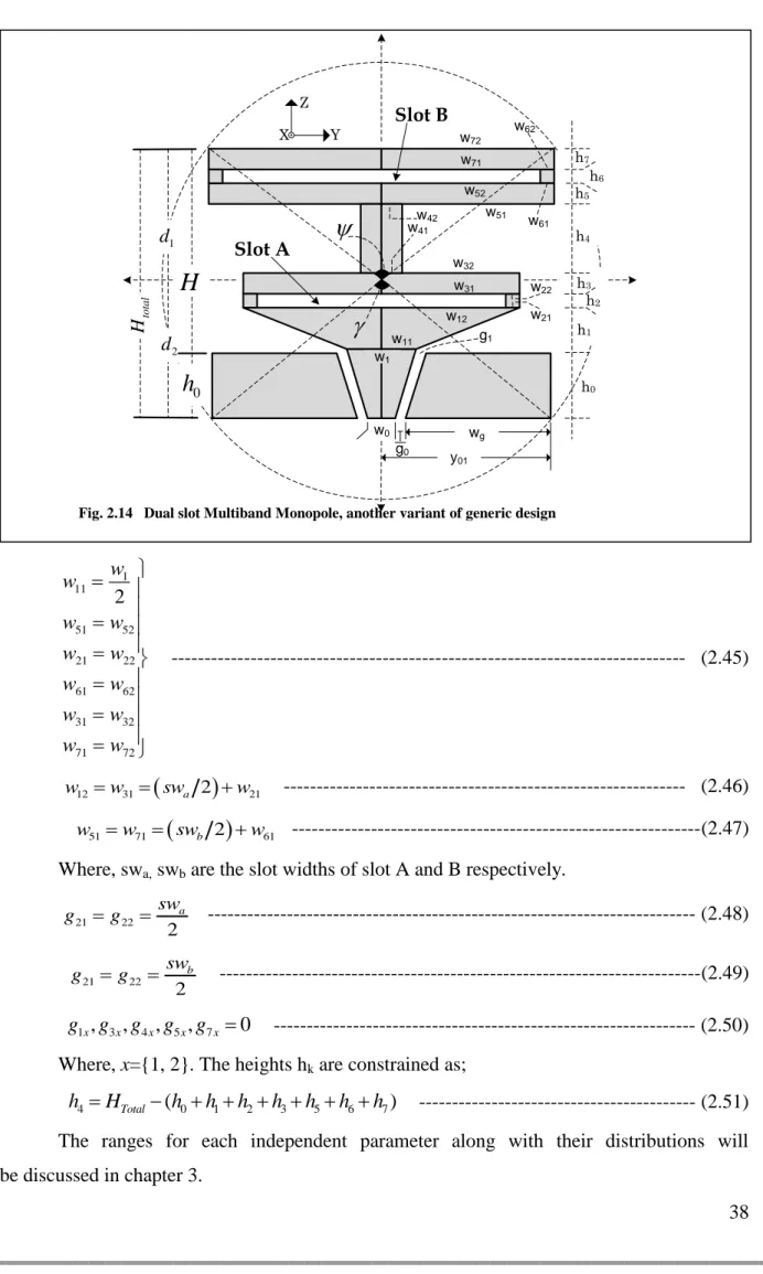
its compactness [40]–[43]. It was originally designed in strip line (DFMS) [42] and microstrip (DFMM) [43] technologies. Here a CPW version of this antenna can be envisaged (Fig. 2.4d). Finally, a multiband behavior can be achieved with a double slot design (Fig. 2.4f). All these antenna designs are discussed in detail in the subsequent sections.
22 This concept of generic geometry can also
be applied to balanced antennas such as dipoles; At least two alternative designs may be derived: first, the ground plane can be ―shaped‖. Second, a purely balanced version can be designed thanks to a lateral feed, either preserving a single layer technology – a wideband CPW to Coplanar Strip (CPS) balun being required in this case –, or with
a bi-layer technology and a microstrip to
symmetrical strip (broadside) balun (Fig. 2.3).
Generic Design (a) Disc Monopole Design (e) Triangular or Bow-tie Design (c) Dual Feed Monopole Design (d) Multi-Band Design (f) Staircase Monopole Design (b)
Fig. 2.4 various design derivatives of generic geometry
z
y
Fig. 2.3 Generic BALANCE dipole design
23
2.3.
Parameterization
One of the most important free parameters is the radius Rmin of the smallest
circumscribing sphere1, from which most of the design parameters depend directly or indirectly. It is indeed directly related to the lower corner frequency, hence to the frequency bandwidth.
The angles and determine the upper yK gK2wK2 and the lower (
1
01 2 0 0 g
y
w
g
w
) widths respectively. In addition these angles control thetotal height Htotal.
1 2 min cos cos
2 2
Total
H d d R
--- (2.1)
The top width yK and bottom width y01 are defined as
01 minsin 2 y R
--- (2.2) minsin 2 K y R
--- (2.3) In practice, Rmin is fixed at first, and and are uniformly distributedrandom variables (rv) within the desired ranges. As can be seen, numerous geometries with different heights and widths can be addressed for a given circumscribing sphere
Let κ = H/h0, the radiating part height (H) to the ground plane height (h0),
then by changing κ various samples of different ground plane heights can be generated. 1 Total H H --- (2.4) 0 1 Total H h --- (2.5)
The CPW feed is defined by the independent parameters w0, g0, α, (Fig.
2.5) and the dependent parameters w1, g0, wg, calculated as:
1 Actually, the minimal sphere may be larger than the sphere of radius R
min as defined in Fig. 2.5 (for its simplicity), since any inner layer k (k < K) may have an outside part for large values of gkn + wkn. But for most practical cases the criterion is verified (or ―almost verified‖). Alternatively, to strictly fulfill the criterion, the following conditions can be added:
2 2 2 2
1 1 2 2 1
, k k min k and k k min k
k K g w R z g w R z
24 0 1 0 13 2 , with tan 30 2 h w w --- (2.6)
1 1 0 g
g --- (2.7) 0 01 0 2 g w w y g --- (2.8) Thus, the angle decides the width w1 (Fig. 2.5), is a random variableuniformly distributed in the range of [0—1]. All the parameters and their relations defined so far are common to the various geometries. Table 2.1 summarizes these parameters.
Different antenna profiles/designs can be conceived by varying the width {wk1, wk2}, heights hk and gaps {gk1, gk2} of the individual trapezoids.
2.4.
Monopole Designs
The broadband planar monopole antennas have proved to be excellent radiators over very large BW. They commonly find their place in numerous applications. Some of their characteristics are mentioned below:
Fig. 2.5 Parameterization of generic geometry
O 11 g 12 g 21 g 51 g 22 w 32 w 41 w 42 w 52 w 51 w 31 w 21 w 12 w 11 w 11 w g11 12 g 52 g 51 g 42 g 12 w 21 w 22 w 31 w 32 w 41 w 42 w 51 w 52 w 0 g 1 g 1 w 0 w g w g h 1 g 0 g g w g h 52 g 22 g g22 21 g 32 g g32 31 g 31 g 41 g g41 42 g 0
h
H
1 d total H 01y
Ky
5 h 4 h 3 h 2 h 1 h 0 hz
y
minR
d225 Very large impedance bandwidth. For example, until now, the achieved impedance BW for VSWR = 2:1 have reached about 10:1 for an elliptical planar monopole and 80% for other planar monopoles [44]−[57].
Table 2.1 Summary of common parameters
Parameter Description
Rmin Radius of the circumscribing sphere
Angle that decides the top edge width of the antenna
Angle that decides the bottom edge width of the antenna
κ Ratio of radiating part height to ground plane height
w0 CPW beginning width
g0 CPW beginning gap
Angle between h0 and w1; decides the value of w1
Random number; decides the value of g1 the end gap for
CPW
Maximum flexibility in reconfigurable radios [53].
Stable radiation patterns with a reflection coefficient in excess of 10 dB over an extremely wide frequency range [56][57][61][62].
Capability of multi band operations with Omni-directional radiation patterns in azimuth for all operation bands [57][60][63][64][68].
Low fabrication cost and ease of manufacture.
Compact size, linear phase response and acceptable radiation efficiency. Electrical heights less than λ/4 achieved.
Interference immunity with existing wireless networking technologies by using band-notched planar monopole antenna[53] [56].
In the literature a number of monopole UWB design have been published, such as heart-shape, U-shape, circular-shape and elliptical-shape, etc. In the