HAL Id: hal-01074568
https://hal.archives-ouvertes.fr/hal-01074568
Submitted on 14 Oct 2014
HAL is a multi-disciplinary open access
archive for the deposit and dissemination of
sci-entific research documents, whether they are
pub-lished or not. The documents may come from
teaching and research institutions in France or
abroad, or from public or private research centers.
L’archive ouverte pluridisciplinaire HAL, est
destinée au dépôt et à la diffusion de documents
scientifiques de niveau recherche, publiés ou non,
émanant des établissements d’enseignement et de
recherche français ou étrangers, des laboratoires
publics ou privés.
Collaborative Overlay Power Management based on the
Delay-Power Tradeoffs
Han Yan, Cédric Gueguen, Bernard Cousin, Jean-Paul Vuichard
To cite this version:
Han Yan, Cédric Gueguen, Bernard Cousin, Jean-Paul Vuichard.
Collaborative Overlay Power
Management based on the Delay-Power Tradeoffs.
FGCT 2014 :
Third International
Confer-ence on Future Generation Communication Technologies, Aug 2014, London, France. pp.39 - 45,
�10.1109/FGCT.2014.6933228�. �hal-01074568�
Collaborative Overlay Power Management based on
the Delay-Power Tradeoffs
Han YAN
∗‡, C´edric GUEGUEN
∗, Bernard COUSIN
∗, Jean-Paul VUICHARD
‡∗University of Rennes 1 / IRISA;‡Orange Labs
{han.yan;cedric.gueguen;bernard.cousin}@irisa.fr {han.yan;jeanpaul.vuichard}@orange.com
Abstract—Achieving an energy-efficient home network while providing high quality user service is and will continue to be a significant need for the future residential environment. In this home network environment, numerous home appliances are widely used and also integrally turned on to contribute to the home network service. But these appliances are used partially in different service requirements. Therefore, in this paper, we propose a collaborative overlay power management system in which appliances can be partially turned on depending on the request of the services. Moreover, by learning a users behavior, the collaborative overlay power management could trend to minimize power consumption or trend to minimize the waiting delay. Regarding research on the different power consumption and waiting delay tradeoffs, our proposition allows for satisfying different user requirements on power consumption and waiting delay.
Index Terms—Home network, Energy saving, Green network-ing, Overlay control network, Low Power, Collaborative system
I. INTRODUCTION
Energy saving is recognized as a key issue in global warming and climate change. According to the recent re-port of the European Commission, Eurostat, there are three dominant energy consumption categories: transport, household and industry. Household energy consumption increased to 26.7% [1] of total energy consumption in 2010 and this category of energy consumption is greater than industry energy consumption. Furthermore, the price of electricity is constantly increasing, with European residential electricity prices increas-ing on average 2% faster than inflation in 2012. The greatest price increases from 2012 to 2013 were observed in Romania (26%) and in Estonia (23 %) [2]. It is therefore crucial to reduce energy consumption in home environments.
The first challenge is that, in home environments, in recent decades, there has been a proliferation of connected devices and the number of connected devices has led to a sharp increase in energy consumption in the home. With many different types of appliances in a home network, such as home gateway (HGW), Set-Top Box (STB), network attached stor-age (NAS), laptops, etc., household energy saving approaches should take these different connected appliances and their different usages and functionalities into account.
In the literature, techniques have been proposed to reduce energy consumption at the device level. Using dynamic power management [3] [4], devices can be switched to a lower power mode when the service demand is reduced. In addition,
algorithms have been proposed minimizing the energy con-sumption of device components. For instance, Maruti proposed a method that reduces the power supply when there is less traffic over Ethernet links [5], and there are other proposals aiming to control the memory in order to be more power efficient [6] [7]. It is not sufficient, however, to save energy only at the level of each individual device. The power status of each home device is independent of the others. For example, when all family devices are not operational or not in use, it can be concluded that the home gateway no longer needs to provide a local network, and its Ethernet and WiFi components can be turned off. The activity or power status of one appliance is not independent information; this information can be used to manage other appliances. Consequently, our solution provides a collaborative system to control the power status of home connected devices at the network level and the power states of functional blocks in these collaborative devices at the device level.
In earlier works, Youn-Kwae Jeong et al. proposed a solu-tion that controls home network devices by reconfiguring the power control element (PCE). Their proposed solution only supplies power to the devices and the functional elements that are related to requested services [8]. In their approach, all functional elements are turned on at the beginning of the service, despite the fact that early functional modules are not needed at that time. The UPnP AV use case [9]] is a good example to illustrate why there is a time lapse between requested functional blocks in one service: the user controls the home devices with an UPnP Control Point (laptop, smart-phone, iPad or other tablet) and wants to watch a film on his UPnP Media Renderer (STB). This film is saved on his UPnP Media Server (NAS). For this service, the content directory functional block on the UPnP Media Server is needed at the beginning of the service. The decoder functional block on the UPnP Media Renderer is required later by the service. Therefore, our solution provides collaborative management according to the service request on each functional block in order to control the right function block at the right moment. Another challenge is that user behavior is an important factor in the home network energy control system. By learning user behavior habits, the power management system could anticipate the requests of the functional blocks while one service is launched. Accordingly, the power management could make more precise power control decisions that are adaptive to the learned behaviors of a given family. Moreover, different
users have different requirements: some prefer to be more energy efficient, some do not want their service experience to be affected, and some want both. Therefore, our solution proposes a learning power management approach for the purpose of satisfying the user service demand.
A final challenge is that, in order to be power-efficient and reactive to user demand, the solution should be able to control any device at any time. This requires an always-on connection. In order to ensure power management, the solution proposed by Youn-Kwae Jeong et al. needs a permanent connection (Ethernet or WiFi) which is said to consume more than 1 Watt. Unlike earlier power management solutions which need to maintain a WiFi connection or an Ethernet connection, in our former works [10] [11], we proposed a low power overlay network for the centralized monitoring and control of home network devices by using the following technologies: ZigBee [12], UPnP network [13], 6LowPan [14], and Bluetooth low energy [15]. These can be considered for an infrastructure of a green overlay control network. Home connected appliances can nowadays be turned on by a command from Wakeup on USB [16] or Wake on LAN (WoL) [17].
The main contributions of our collaborative overlay power management are: 1) the proposition of a collaborative home network. 2) Our power management approach takes into account the user behavior. 3) The control messages are sent over a low power overlay network.
The rest of the paper is organized as follows. Section II de-scribes our collaborative overlay power management. Section III presents the service pattern, the power consumption model and the delay model. Section IV presents the setup of the simulation. Section V. analyzes the results of the simulation. Section VI draws conclusions from our findings.
II. PROPOSED COLLABORATIVE OVERLAY ENERGY CONTROL POWER MANAGEMENT SYSTEM
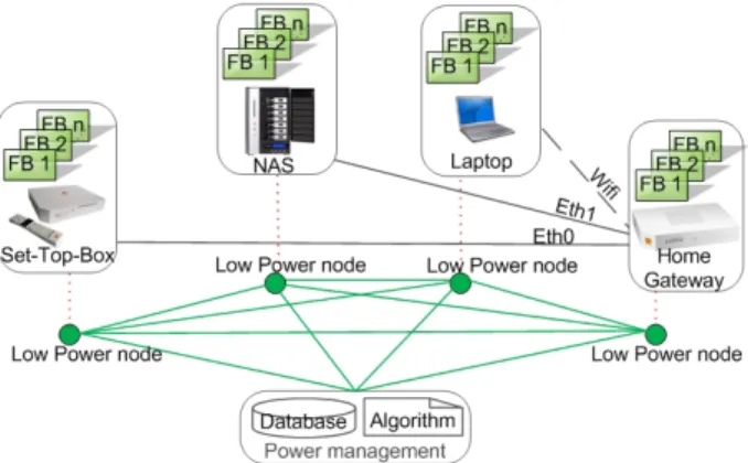
In this section, we detail the collaborative overlay control system, as shown in Fig.1, which is composed of the power management system, the collaborative home network con-nected devices, and the low energy overlay control network.
Fig. 1. Collaborative home network service management
A. Power management
Power management: power management comprises a database and a decision algorithm entity. The database is used to store records of user habits when they use services. When the service is requested for the first time, the database gathers the information relating to the user request services in order to learn the habits of this family and the information relating to the family user reaction. According to the information collected by the system, the power management controls the device with fine granularity. The granularity of the control is said to be fine because the control can turn on/off the functional blocks that are necessary for the collaborative service at the point at which they are requested. We assume each home network collaborative service involves one or more devices that cooperate together to meet the service demand of the family.
A typical collaborative UPnP audio video service pattern within four devices is shown in Fig.4 (below). The user uses their UPnP Control Point (laptop) to search for a film, which is stored on the UPnP Media Server (NAS) in order to watch it on the UPnP Media Renderer (STB). Each service occurrence requires different Functional Blocks (FB) in different devices. The user firstly needs the connection between their laptop and their NAS to be guaranteed by the HGW. Then, when the user has found the film saved on the NAS, the STB should be turned on in order to play the film. The content directory (FB1), connection manager (FB2), transfer server (FB3) functional blocks in NAS and the video stream decoder (FB1), display interface (FB2), authentication (FB3) and transfer client (FB4) functional blocks in STB are requested. The HGW provides the connection block during the entire service.
This typical UPnP AV use case requires different connected devices to participate at different points in the service. When the user decides to start the service, according to the infor-mation saved about this service, the power management sends control messages to each device as they are required. The requested information can be pre-saved by the user in the power management, or by a process of auto-learning in the power management. With the collaborative system, only the required components are turned on, and the components which are no longer needed when the service is terminated are turned off.
Fig. 2. A service pattern example
B. Home network connected devices
In our proposal, we not only assume that collaborative services involve several devices, but also that each device is collaborative into one or more functional blocks. It is
necessary to detail how one functional block pattern works in one device during one service as shown in Figure 3. If the power management decided to turn on the functional block before the request of the service, as shown in Fig.3(a), FB has three phases: starting, idling and operating. The starting phase defines the necessary starting time that begins when the functional block is turned on (tdec−on) and lasts until
the functional block is available (tavailable). Then FB may
be in the idle phase during a period of no activity until it is requested by a service. Once this FB is requested (trequest),
it could execute the operation immediately since it is already operational. On the contrary, as shown in Fig. 3(b), the request of this functional block may happen before this FB is available. FB will begin the service execution immediately (tdec−on)
upon becoming available (tavailable) without having an idle
period. In this case, the starting phase becomes a waiting delay before executing the service operation.
Fig. 3. Functional block is turned on (a) in advance (b) by the service request
C. Low energy communication overlay network
Low energy communication overlay network: On each home network device, we propose an overlay low energy node by considering the characteristics of the device. These low power nodes form a low power overlay control network. The control message can be sent via ZigBee, Bluetooth Low Energy (BLE) or an UPnP Low Power (UPnP LP) network, depending on the capacity of the device. For example, it is possible that a new generation tablet will be equipped with BLE instead of having to add a ZigBee dongle to this tablet. The power consumption of a ZigBee module or BLE chipset is about a few milliwatts, which is much less than that of an Ethernet or WiFi network card, which consumes about 1.5 Watts. In our system, we assume that the overlay power control messages will be sent by a ZigBee or BLE module in order to ensure a low-power and always-on network.
In this section, we have described our overall architecture of our collaborative and collaborative overlay power management (COPM). The power-delay tradeoff (PDT) algorithm of this COPM architecture will be presented in the following section.
III. PROPOSEDALGORITHM
Before describing the collaborative overlay power manage-ment power-delay tradeoff algorithm in detail, it is worthwhile to know how the power energy and delay models are con-structed.
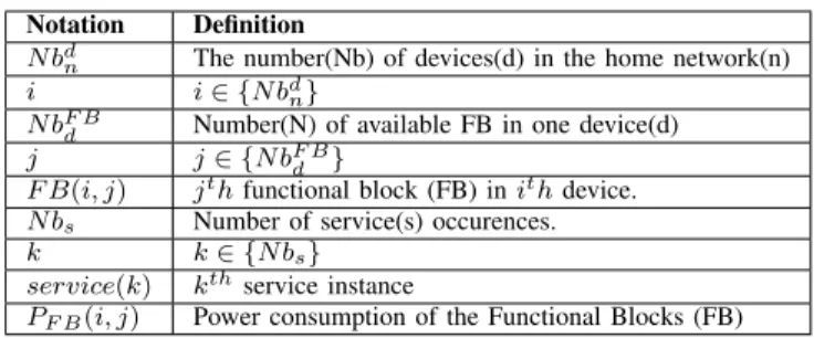
TABLE I NOTATIONSUMMARY
Notation Definition
N bdn The number(Nb) of devices(d) in the home network(n)
i i ∈ {N bdn}
N bF Bd Number(N) of available FB in one device(d) j j ∈ {N bF B
d }
F B(i, j) jth functional block (FB) in ith device.
N bs Number of service(s) occurences.
k k ∈ {N bs}
service(k) kthservice instance
PF B(i, j) Power consumption of the Functional Blocks (FB)
A. Energy and delay models
The notation of the parameters is described in the Table I. The energy consumption of one service occurrence can be calculated using the following formula (1): where the Don(i, j, k) is the on duration of the functional block in
formula ( 2), which is composed of the starting duration, the utilization duration of F B(i, j) in service(k) and the idle duration. The starting duration is the necessary period to launch a FB. The utilization duration depends on the service requirement. The idle duration may be null when the service request trequest(i, j, k) is earlier than the FB being available
at tavailable(i, j, k). E(k) = N bdn X i=1 N bF Bd X j=1 PF B(i, j) × Don(i, j, k) (1) Don(i, j, k) =
Dstarting(i, j, k) + Didle(i, j, k) + Dutilization(i, j, k)
(2) The Delay(k) is the total waiting time for the service(k), described in formula (3). There are two cases: if the FB is available before the arrival of the service request , there is no waiting time for the user. Thus, the delay is null in this case. Otherwise, if the service request arrives before the FB is available, the waiting time is the period from the trequest(i, j, k), to thetavailable(i, j, k). The delay is the
difference between these two moments. Delay(i) = N bd n X i=1 N bF B d X j=1
{0, trequest(i, j, k) < tavailable(i, j, k) Dstarting(i, j, k), else
(3)
After modeling our service patterns, function block patterns, and energy and delay calculations, we applied our COPM-PDT propositions and other power management systems to the models.
B. Power-Delay Tradeoff (PDT) algorithm
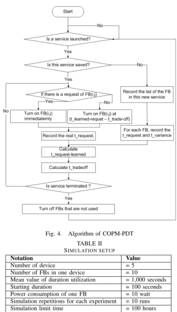
The proposed COPM Power-Delay Tradeoff (COPM-PDT) algorithm is illustrated in Fig. 4. The COPM-PDT is launched by a daemon process which checks if one service is launched. If yes, the COPM-PDT will check if the service description has already been saved in the database. If this is a new occurring service, the power management will learn the functional blocks that were used by this new service and the service
request time for each functional block trequest−learned(i, j).
The formulas (4) calculates how the COPM-PDT learns the trequest−learned(i, j). If the service has already been learned
by the power management, there will be two cases. In the first case whent COPM-PDT detects a request for one FB, the FB will be turned on immediately. User needs to wait that the required FBs are ready. In the second case when COPM-PDT does not detect an request for an FB, it controls the FB based on the learned user behavior. It means that each FB will be turned on tdec−on, in the formula (5):
trequest−learned(i, j) =
PN bs
k=1trequest(i, j, k − 1)
N bs
(4) tdec−on(i, j, k) = trequest−learned(i, j) − ttradeof f (5)
ttradeof f(i, j) = trequest−variance(i, j, k) × α (6)
The decision is based on the mean value of all recorded learned requests. Based on the learned mean value, COPM-PDT turns on the FB in advance of ttradeof f in order to
minimize the waiting delay. The ttradeof f will be configured
by the user satisfaction requirement α and the variance of the request (trequest−variance) as shown in formula (6). The
variance of the request depends on how is user behavior. For example, one user each day turns on his STB at around 8 pm; sometimes it could be earlier or later depending on the users behavior. For the user who is more concerned about power consumption and willing to wait, the user satisfaction requirement coefficient will be small. And the ttradeof f will
be relatively small. On the contrary, the ttradeof f will be
relatively greater if the user wishes to start the service immedi-ately. This value will be investigated in the simulation. In both two cases, after receiving the FB requests, COPM-PDT will update his database in order to calculate the new mean value of the request (trequest−learned(i, j)) and the tradeoff value
(ttradeof f). And this new calculated trequest−learned(i, j) and
ttradeof f will help the power management system control the
devices for the next time when the service will be called. At the end of the service, COPM-PDT will turn off the FBs that are not needed by this or other services.
IV. SETUP OF SIMULATIONS AND ANALYSIS OF RESULTS
In this section, we will firstly present the setup of our simulation and the scenarios, and then we will analyze the simulation results in different scenarios.
A. Simulation setup
In order to accurately measure power consumption and the waiting delay of each power management, we implemented a typical home network, which was capable of executing a collaborative service in omnet++. In this typical home network, we had 5 devices that cooperate to provide services in the home network. The service inter arrival time follows an exponential distribution whose mean value is 5,000 seconds. Each arriving service requires different components in the device to achieve the complete service. The use of each component also follows an exponential distribution whose
Fig. 4. Algorithm of COPM-PDT TABLE II
SIMULATION SETUP
Notation Value Number of device = 5 Number of FBs in one device = 10
Mean value of duration utilization = 1,000 seconds Starting duration = 100 seconds Power consumption of one FB = 10 watt Simulation repetitions for each experiment = 10 runs Simulation limit time = 100 hours
mean value is 1,000 seconds. It is also possible that there is a time lapse between the beginning of the service and the request of each FB. This time lapse follows a normal distribution. The parameters are described in TABLE II.
Firstly, for the purpose of measuring the power efficiency and the waiting delay of our version of power management, we will tune the mean value of the request of the functional block. In this case, during the simulation limit time, our power management could have 3 scenarios:
α=0.99, 99% of services are executed with a minimum waiting delay.
α=0.75, 75% of services are executed with a minimum waiting delay.
α=0.50, 50% of services are executed with a minimum waiting delay.
Secondly, in order to analyze the solutions, by tuning the tradeoff percentage, we will investigate the different power-delay tradeoff. We compare our COPM-PDT proposition ver-sus User control power management and PCE power manage-ment:
User control power management: We assume a user who is mindful of energy conservation. This user turns on each device integrally when its service is needed, and turns off each device when the service is no longer required. This version of power management could be seen as an ideal behavior for the point of view of delay and the worst behavior on the user which have to trigger every events.
PCE: The service is started with all necessary power control elements on at the beginning of the service. They will be turned off when the user finishes using the services.
B. Simulaton Results
1) The request of the functional block: In this study, we first examined the changes on the request of functional blocks in 3 different tradeoff scenarios. To study the relationship between the trequestand the power consumption and waiting delay. The
distribution law of the request time of FB ( trequest(i, j, k))
follows a normal distribution whose standard deviation is 100 seconds. We varied the mean value of the distribution of the requested functional block from 0 seconds to 1,000 seconds.
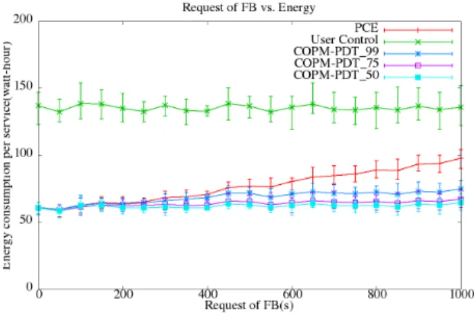
From Fig. 5 we can see that the energy consumption of the user control power management is almost stable because the devices are turned on integrally when the service requests arrive and the devices are turned off integrally when the services are terminated. Therefore, the energy consumption of the user control power management corresponds to the service utilization duration. In this experience, the utilization duration does not change, thus, the energy consumption of the user control remains stable. The energy consumption of the PCE power management increases continuously, since the PCE turns on all participating functional blocks from the beginning of the service. The increasing of the trequest
signifies that the requests of functional blocks are arriving increasingly later. The functional blocks will to consume more energy in the no-activity period. So, with the PCE, the total energy consumption in one service increases as the trequestincreases. The COP M − P DT99, COP M − P DT75,
COP M − P DT50are configured to assure respectively 99%,
75%, 50% functional blocks should be ready while the request of the functional block is arriving. Therefore, the functional blocks in the COP M − P DT99 are turned on much earlier
than the COP M − P DT75 and COP M − P DT50. Thus,
the energy consumption of COP M − P DT99 is higher than
COP M − P DT75and COP M − P DT50. Fig. 6 shows the
average waiting delay for each service. The user control power management turns on the devices when the service request arrives. Thus, there is always a waiting delay in the starting time before the device becomes available. The PCE has the smallest waiting delay because all of the functional blocks are turned on at the beginning of the service. The waiting delay of the PCE comes from the functional blocks that are used first. Although some of the functional blocks are needed later, they are already turned on. As explained before, the FBs controlled by COP M − P DT99 are turned on much earlier than the
COP M −P DT75and COP M −P DT50in order to minimize
the waiting delay. Therefore the COP M − P DT99has almost
Fig. 5. Energy while varying the request of Functional Block(FB)
Fig. 6. Delay while varying the request of Functional Block(FB)
the minimum waiting delay that we could achieve. COP M − P DT75has a higher delay since the functional blocks are often
turned later than the COP M − P DT99.COP M − P DT50has
the shortest delay.
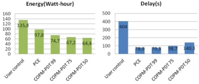
After seeing the trends of energy consumption and delay by varying the request of the functional block, we will zoom at the moment that the mean value of the request is 1,000 seconds in Fig. 7 and TABLE III. We can see that our proposition COP M −P DT99is the most energy efficient and a minimum
delay: COP M −P DT99consumes 74.7 watt-hours, compared
with PCE we could have a 23.62% energy gain. In the same scenario, COP M − P DT99cause only 0.5% increased delay
compared with PCE. For the users who prefer to have more energy gain at 31.29 % and may accept 20.06% delay more than PCE, they could choose COP M −P DT75. For those who
want to obtain the maximum energy gain without considering the delay, the energy gain could be more than 34.15%.
2) The tradeoff coefficient: In this study, we will investigate the tradeoff percentage parameter from 0.01 to 0.99. . We
TABLE III
SIMULATION ENERGY AND WAITING DELAY RESULTS
α 99 75 50
Increased Delay vs PCE 0.5% 20.06% 43.75% Energy gain vs PCE 23.62% 31.29% 34.15%
Fig. 7. Energy consumption and delay while the request at 1000 seconds
fixed the mean value of the distribution of the requested functional block at 1,000 seconds with a standard deviation fixed at 100 seconds. Fig. 8 shows how energy consumption changes while we tune the tradeoff coefficient. Fig. 9 shows how waiting delay changes in the same condition. These two figures can be divided into 3 regions. In the first part, while the coefficient is smaller than 0.25, the COPM-PDT trends to maximize the power consumption with a relatively high delay (Between 210 seconds to 400 seconds per service). The home network user may find this difficult to accept. The second region of tradeoff coefficient is between 0.25 and 0.6. The energy efficiency is almost the same as in the first region. Moreover the delay decreases almost by half compared with the first region. The tradeoff coefficient in the last region is from 0.6 to 0.99. Although the COPM-PDT is a little bit less energy efficient than the second region, the algorithm reaches almost the minimum waiting delay that we could achieve in one service. Based on this experience, the COPM-PDT provides 3 regions of choices for different user requirements in energy efficiency or waiting delay or a tradeoff between these two factors.
Fig. 8. Energy while varying the request of tradeoff coefficient
V. CONCLUSION
In this paper, we developed a collaborative overlay power management that offers several possible tradeoffs between the power consumption and the waiting delay in the home net-work. Based on the learned knowledge of the user’s behavior, our COPM-PDT proposal is capable to control collaborative
Fig. 9. Delay while varying the request of tradeoff coefficient
devices by turning on the only requested functional blocks. Our proposed COPM-PDT algorithm exploits the tradeoff of power consumption and waiting delay. The results show that our proposition could be energy efficient and provide a low waiting delay for different user requirements. The results also show that COPM-PDT could achieve the minimum waiting delay or the maximum energy efficiency which would depend on the user exigencies. There is always a tradeoff between power consumption and waiting delay. The future work will be to extend the proposed algorithm for more collaborative services that may have dependences between each other, which may provide a better energy efficiency and less waiting delay home environment.
REFERENCES
[1] S. E. Eurostat, “Consumption of energy,” Tech. Rep., 2012.
[2] “European residential energy pricing report 2013,” Vaasa ETT, Tech. Rep., 2013.
[3] L. Benini, R. Bogliolo, and G. D. Micheli, “A survey of design techniques for system-level dynamic power management,” IEEE Trans-actions on VLSI Systems, vol. 8, pp. 299–316, 2000.
[4] E.-Y. Chung, L. Benini, A. Bogiolo, and G. De Micheli, “Dynamic power management for non-stationary service requests,” in Proceedings of the conference on Design, automation and test in Europe, ser. DATE ’99. New York, NY, USA: ACM, 1999.
[5] Maruti, “Dynamic ethernet link shutdown for energy conservation on ethernet links,” in ICC, 2007, pp. 6156–6161.
[6] B. Khargharia, S. Hariri, and M. S. Yousif, “An adaptive interleaving technique for memory performance-per-watt management,” IEEE Trans. Parallel Distrib. Syst., vol. 20, no. 7, pp. 1011–1022, Jul. 2009. [7] X. Fan, C. Ellis, and A. Lebeck, “Memory controller policies for
dram power management,” in Proceedings of the 2001 international symposium on Low power electronics and design, ser. ISLPED ’01. New York, NY, USA: ACM, 2001, pp. 129–134.
[8] Y.-K. Jeong, I. Han, and K.-R. Park, “A network level power manage-ment for home network devices,” Consumer Electronics, IEEE Transac-tions on, vol. 54, no. 2, pp. 487–493, May 2008.
[9] J. Ritchie and T. Kuehnel, UPnP AV Architecture:1, The UPnP forum Std., 2002.
[10] H. Yan, C. Gueguen, B. Cousin, J. P. Vuichard, and G. Mardon, ”Green Home Network based on an Overlay Energy Control Network”, J. L. M. Shafiullah Khan, Ed. CRC press, Taylor & Francis Group, USA, 2013. [11] H. Yan, F. Fontaine, O. Bouchet, J.-P. Vuichard, J.-P. Javaudin, M. Lebouc, M.-H. Hamon, B. Cousin, and C. Gueguen, “Hope: Home power efficiency system for a green network,” Turin, Italy, 2013. [12] S. Farahani, ZigBee Wireless Networks and Transceivers. Newton, MA,
USA: Newnes, 2008.
[14] J. Hui and D. Culler, “Extending ip to low-power, wireless personal area networks,” Internet Computing, IEEE, vol. 12, no. 4, pp. 37–45, July 2008.
[15] E. Mackensen, M. Lai, and T. Wendt, “Bluetooth low energy (ble) based wireless sensors,” in Sensors, 2012 IEEE, Oct 2012, pp. 1–4. [16] M. Flannery, “Method and apparatus of providing power management
using a self-powered universal serial bus (usb) device,” Aug. 25 1998, 5,799,196 US Patent.
[17] C. Ryu, “Method and apparatus for controlling power of computer system using wake up lan (local area network) signal,” Jul. 8 2003, 6,591,368 US Patent.