HAL Id: hal-01239128
https://hal.inria.fr/hal-01239128
Submitted on 7 Dec 2015
HAL is a multi-disciplinary open access
archive for the deposit and dissemination of
sci-entific research documents, whether they are
pub-lished or not. The documents may come from
teaching and research institutions in France or
abroad, or from public or private research centers.
L’archive ouverte pluridisciplinaire HAL, est
destinée au dépôt et à la diffusion de documents
scientifiques de niveau recherche, publiés ou non,
émanant des établissements d’enseignement et de
recherche français ou étrangers, des laboratoires
publics ou privés.
Public Domain
Scientific Workflows on Clouds
Radu Tudoran, Alexandru Costan, Gabriel Antoniu
To cite this version:
Radu Tudoran, Alexandru Costan, Gabriel Antoniu. OverFlow: Multi-Site Aware Big Data
Man-agement for Scientific Workflows on Clouds. IEEE transactions on cloud computing, IEEE, 2016,
�10.1109/TCC.2015.2440254�. �hal-01239128�
IEEE TRANSACTIONS ON CLOUD COMPUTING, VOL. X, NO. X, AUGUST 2014 1
OverFlow: Multi-Site Aware Big Data
Management for Scientific Workflows on
Clouds
Radu Tudoran, Member, IEEE, Alexandru Costan, Member, IEEE,
and Gabriel Antoniu, Member, IEEE
Abstract—The global deployment of cloud datacenters is enabling large scale scientific workflows to improve performance and
deliver fast responses. This unprecedented geographical distribution of the computation is doubled by an increase in the scale of the data handled by such applications, bringing new challenges related to the efficient data management across sites. High throughput, low latencies or cost-related trade-offs are just a few concerns for both cloud providers and users when it comes to handling data across datacenters. Existing solutions are limited to cloud-provided storage, which offers low performance based on rigid cost schemes. In turn, workflow engines need to improvise substitutes, achieving performance at the cost of complex system configurations, maintenance overheads, reduced reliability and reusability. In this paper, we introduce OverFlow, a uniform data management system for scientific workflows running across geographically distributed sites, aiming to reap economic benefits from this geo-diversity. Our solution is environment-aware, as it monitors and models the global cloud infrastructure, offering high and predictable data handling performance for transfer cost and time, within and across sites. OverFlow proposes a set of pluggable services, grouped in a data scientist cloud kit. They provide the applications with the possibility to monitor the underlying infrastructure, to exploit smart data compression, deduplication and geo-replication, to evaluate data management costs, to set a tradeoff between money and time, and optimize the transfer strategy accordingly. The system was validated on the Microsoft Azure cloud across its 6 EU and US datacenters. The experiments were conducted on hundreds of nodes using synthetic benchmarks and real-life bio-informatics applications (A-Brain, BLAST). The results show that our system is able to model accurately the cloud performance and to leverage this for efficient data dissemination, being able to reduce the monetary costs and transfer time by up to 3 times.
Index Terms—Big Data, scientific workflows, cloud computing, geographically distributed, data management
F
1
I
NTRODUCTIONW
ITH their globally distributed datacenters, cloud infrastructures enable the rapid develop-ment of large scale applications. Examples of such ap-plications running as cloud services across sites range from office collaborative tools (Microsoft Office 365, Google Drive), search engines (Bing, Google), global stock market analysis tools to entertainment services (e.g., sport events broadcasting, massively parallel games, news mining) and scientific workflows [1]. Most of these applications are deployed on multiple sites to leverage proximity to users through content delivery networks. Besides serving the local client requests, these services need to maintain a global coherence for mining queries, maintenance or moni-toring operations, that require large data movements. To enable this Big Data processing, cloud providers have set up multiple datacenters at different geograph-ical locations. In this context, sharing,disseminat-• R. Tudoran is with Inria / ENS Rennes, France. E-mail: [email protected]
• A. Costan is with IRISA / INSA Rennes, France. E-mail: [email protected]
• G. Antoniu is with Inria Bretagne Atlantique, Rennes, France. E-mail: [email protected]
ing and analyzing the data sets results in frequent large-scale data movements across widely distributed sites. The targeted applications are compute inten-sive, for which moving the processing close to data is rather expensive (e.g., genome mapping, physics simulations), or simply needing large-scale end-to-end data movements (e.g., organizations operating several datacenters and running regular backup and replication between sites, applications collecting data from remote sensors, etc.). In all cases, the cost savings (mainly computation-related) should offset the signif-icant inter-site distance (network costs). Studies show that the inter-datacenter traffic is expected to triple in the following years [2], [3]. Yet, the existing cloud data management services typically lack mechanisms for dynamically coordinating transfers among differ-ent datacdiffer-enters in order to achieve reasonable QoS levels and optimize the cost-performance. Being able to effectively use the underlying storage and network resources has thus become critical for wide-area data movements as well as for federated cloud settings.
This geographical distribution of computation be-comes increasingly important for scientific discovery.
In fact, many Big Data scientific workloads enable nowadays the partitioning of their input data. This allows to perform most of the processing
indepen-dently on the data partitions across different sites and then to aggregate the results in a final phase. In some of the largest scenarios, the data sets are already partitioned for storage across multiple sites, which simplifies the task of preparing and launching a geographical-distributed processing. Among the no-torious examples we recall the 40 PB/year data that is being generated by the CERN LHC. The volume overpasses single site or single institution capacity to store or process, requiring an infrastructure that spans over multiple sites. This was the case for the Higgs bo-son discovery, for which the processing was extended to the Google cloud infrastructure [4]. Accelerating the process of understanding data by partitioning the computation across sites has proven effective also in other areas such as solving bio-informatics problems [5].Such workloads typically involve a huge number of statistical tests for asserting potential significant re-gion of interests (e.g., links between brain rere-gions and genes). This processing has proven to benefit greatly from a distribution across sites. Besides the need for additional compute resources, applications have to comply with several cloud providers requirements, which force them to be deployed on geographically distributed sites. For instance, in the Azure cloud, there is a limit of 300 cores allocated to a user within a datacenter, for load balancing purposes; any applica-tion requiring more compute power will be eventually distributed across several sites.
More generally, a large class of such scientific appli-cations can be expressed as workflows, by describing the relationship between individual computational tasks and their input and output data in a declarative way. Unlike tightly-coupled applications (e.g., MPI-based) communicating directly via the network, work-flow tasks exchange data through files. Currently, the workflow data handling in clouds is achieved using either some application specific overlays that map the output of one task to the input of another in a pipeline fashion, or, more recently, leveraging the MapReduce programming model, which clearly does not fit every scientific application. When deploying a large scale workflow across multiple datacenters, the geographically distributed computation faces a bottleneck from the data transfers, which incur high costs and significant latencies. Without appropriate design and management, these geo-diverse networks can raise the cost of executing scientific applications. In this paper, we tackle these problems by trying to understand to what extent the intra- and inter-datacenter transfers can impact on the total makespan of cloud workflows. We first examine the challenges of single site data management by proposing an approach for efficient sharing and transfer of in-put/output files between nodes. We advocate storing data on the compute nodes and transferring files between them directly, in order to exploit data locality and to avoid the overhead of interacting with a shared
file system. Under these circumstances, we propose a file management service that enables high throughput through self-adaptive selection among multiple trans-fer strategies (e.g. FTP-based, BitTorrent-based, etc.). Next, we focus on the more general case of large-scale data dissemination across geographically distributed sites. The key idea is to accurately and robustly pre-dict I/O and transfer performance in a dynamic cloud environment in order to judiciously decide how to perform transfer optimizations over federated data-centers. The proposed monitoring service updates dy-namically the performance models to reflect changing workloads and varying network-device conditions re-sulting from multi-tenancy. This knowledge is further leveraged to predict the best combination of proto-col and transfer parameters (e.g., multi-routes, flow count, multicast enhancement, replication degree) to maximize throughput or minimize costs, according to users policies. To validate our approach, we have implemented the above system in OverFlow, as part of the Azure Cloud so that applications could use it based on a Software as a Service approach.
Our contribution, which extends previous work introduced in [6], [7], can be summarised as follows:
• We implement OverFlow, a fully-automated
single- and multi-site software system for scien-tific workflows data management (Section 3.2);
• We introduce an approach that optimizes the
workflow data transfers on clouds by means of adaptive switching between several intra-site file transfer protocols using context information (Section 3.3);
• We build a multi-route transfer approach across
intermediate nodes of multiple datacenters, which aggregates bandwidth for efficient inter-sites transfers (Section 3.4);
• We show how OverFlow can be used to support
large scale workflows through an extensive set of pluggable services that estimate and optimize costs, provide insights on the environment per-formance and enable smart data compression, deduplication and geo-replication (Section 4);
• We experimentally evaluate the benefits of
Over-Flow on hundred of cores of the Microsoft Azure cloud in different contexts: synthetic benchmarks and real-life scientific scenarios (Section 5).
2
C
ONTEXT ANDB
ACKGROUNDOne important phase that contributes to the total makespan (and the consequent cost) of a scientific workflow executed on clouds is the transfer of its tasks and files to the execution nodes [8], [9]. Several file transfers are required to start the task execution and to retrieve the intermediate and output data. With the file sizes increasing to PBs levels, data handling becomes a bottleneck. The elastic model of the clouds has the potential to alleviate this through an improved
IEEE TRANSACTIONS ON CLOUD COMPUTING, VOL. X, NO. X, AUGUST 2014 3
resource utilization. In this section, we show that this feature has to be complemented by a wider insight about the environment and the application, on one hand, and a two-way communication between the workflow engine and the data management system, on the other hand.
2.1 Terminology
We define the terms used throughout this paper. The cloud site / datacenter: is the largest build-ing block of the cloud. It contains a broad number of compute nodes, which provide the computation power, available for renting. A cloud, particularly a public one, has several sites, geographically dis-tributed on the globe. The datacenter is organized in a hierarchy of switches, which interconnect the compute nodes and the datacenter itself with the outside world, through the Tier 1 ISPs. Multiple output endpoints (i.e., through Tier 2 switches) are used to connect the data center to the Internet [10].
The cloud deployment: refers to the VMs that host a user application, forming a virtual space. The VMs are placed on different compute nodes in separate network partitions in order to ensure fault tolerance and availability for the service. Typically, a load balancer distributes all external requests among the VMs. The topology of the VMs in the datacenter is unknown to the user. Several other aspects are in-visible (or transparent) to users due to virtualization, e.g., the mapping of the IPs to physical nodes, the vicinity of VMs, the load introduced by the neigh-bouring VMs, if any, on the physical node, etc. A deployment is limited to a single site, and depending on commercial constraints and priorities, it can be limited in size. Therefore a multi-site application will rely on multiple-deployments.
The multi-site cloud: is made up of several ge-ographically distributed datancenters. An application that has multiple running instances in several deploy-ments across multiple cloud datacenters is referred to as a multi-site cloud application. Our focus in this paper is on such applications. Although applications could be deployed across sites belonging to different cloud vendors (i.e. cloud federations), they are out of the scope of this work. We plan to address such issues in the context of hybrid clouds in future work.
2.2 Workflow data management
Requirements for cloud-based workflows. In order
to support data-intensive workflows, a cloud-based solution needs to: 1) Adapt the workflows to the cloud environment and exploit its specificities (e.g. running in user’s virtualized space, commodity com-pute nodes, ephemeral local storage); 2) Optimize data transfers to provide a reasonable time to solution;
3) Manage data so that it can be efficiently placed and accessed during the execution.
Data management challenges. Data transfers are
affected by the instability and heterogeneity of the cloud network. There are numerous options, some providing additional security guarantees (e.g., TLS) others designed for a high colaborative throughput (e.g., BitTorrent). Data locality aims to minimize data movements and to improve end-application perfor-mance and scalability. Addressing data and computa-tional problems separately typically achieves the con-trary, leading to scalability problems for tomorrow’s exascale datasets and millions of nodes, and yielding significant underutilization of the resources. Metadata management plays an important role as, typically, the data relevant for a certain task can be stored in multiple locations. Logical catalogs are one approach to provide information about data items location.
Programming challenges. So far, MapReduce has
been the ”de-facto” cloud computing model, com-plemented by a number of variations of languages for task specification [11]. They provide some data flow support, but all require a shift of the appli-cation logic into the MapReduce model. Workflow semantics go beyond the map-shuffle-reduce-merge operations, and deal with data placement, sharing, inter-site data transfers etc. Independently of the pro-gramming model of choice, they need to address the following issues: support large-scale parallelism to maximize throughput under high concurrency, enable data partitioning to reduce latencies and handle the mapping from task I/O data to cloud logical struc-tures to efficiently exploit its resources.
Targeted workflow semantics. In order to
ad-dress these challenges we studied 27 real-life appli-cations [12] from several domains (bio-informatics, business, simulations etc.) and identified a set of core-characteristics:
• The common data patterns are: broadcast,
pipeline, gather, reduce, scatter.
• Workflows are composed of batch jobs with
well-defined data passing schemes. The workflow en-gines execute the jobs (e.g. take the executable to a VM; bring the needed data files and libraries; run the job and retrieve the final result) and perform the required data passing between jobs.
• Inputs and outputs are files, usually written once. • Tasks and inputs/outputs are uniquely identified.
Our focus is on how to efficiently handle and transfer workflow data between the VMs in a cloud deployment. We argue that keeping data in the local disks of the VMs is a good option considering that for such workflows, most of the data files are usually temporary - they must exist only to be passed from the job that produced it to the one that will further process it. With our approach, the files from the virtual disk of each compute node are made available to all other nodes within the deployment. Caching the data where
it is produced and transferring it directly where it is needed reduces the time for data manipulation and minimizes the workflow makespan.
2.3 The Need of site-aware file management for
cloud based workflows
As we move to the world of Big Data, single-site processing becomes insufficient: large scale scientific workflows can no longer be accommodated within a single datacenter. Moreover, these workflows typically collect data from several sources and even the data acquired from a single source is distributed on multi-ple sites for availability and reliability reasons. Cloud let users to control remote resources. In conjunction with a reliable networking environment, we can now use geographically distributed resources: dynamically provisioned distributed domains are built in this way over multiple sites. Several advantages arise from computations running on such multi-site configura-tions: resilience to failures, distribution across par-titions (e.g., moving computation close to data or viceversa), elastic scaling to support usage bursts, etc. However, in order to exploit the advantages of multi-site executions, users currently have to set up their own tools to move data between deployments, through direct endpoint to endpoint communication (e.g. GridFTP, scp, etc.). This baseline option is rela-tively simple to set in place, using the public endpoint provided for each deployment. The major drawback in this scenario is the low bandwidth between sites, which limits drastically the throughput that can be achieved. Clearly, this paradigm shift towards multi-site workflow deployments calls for appropriate data management tools, that build on a consistent, global view of the entire distributed datacenter environment. This is precisely the goal targeted by OverFlow.
3
A
DAPTIVEF
ILEM
ANAGEMENTA
CROSSC
LOUDS
ITES WITHO
VERF
LOWIn this section we show how the main design ideas behind the architecture of OverFlow are leveraged to support fast data movements both within a single site and across multiple datacenters.
3.1 Core design principles
Our proposal relies on the following ideas:
• Exploiting the network parallelism. Building
on the observations that a workflow typically runs on multiple VMs and that communication between datacenters follows different physical routes, we rely on multi-route transfer strate-gies. Such schemes exploit the intra-site low-latency bandwidth to copy data to intermediate nodes within the source deployment (site). Next, this data is forwarded towards the destination
across multiple routes, aggregating additional bandwidth between sites.
• Modeling the cloud performance. The
com-plexity of the datacenters architecture, topology and network infrastructure make simplistic ap-proaches for dealing with transfer performance (e.g., exploiting system parallelism) less appeal-ing. In a virtualized environment such techniques are at odds with the goal of reducing costs through efficient resource utilization. Accurate performance models are then needed, leveraging the online observations of the cloud behavior. Our goal is to monitor the virtualized environ-ment and to predict performance metrics (e.g., transfer time, costs). As such, we argue for a model that provides enough accuracy for au-tomating the distributed data management tasks.
• Exploiting the data locality.The cumulative
stor-age capacity of the VMs leased in one’s deploy-ment easily reaches the TBs order. Although tasks store their input and output files on the local disks, most of the storage remains unused. Mean-while, workflows typically use remote cloud stor-age (e.g., Amazon S3, Azure Blobs) for sharing data [8]. This is costly and highly inefficient, due to high latencies, especially for temporary files that don’t require persistent storage. Instead, we propose aggregating parts of the virtual disks in a shared common pool, managed in a distributed fashion, in order to optimize data sharing.
• Cost effectiveness.As expected, the cost closely
follows performance. Different transfer plans of the same data may result in significantly different costs. In this paper we ask the question: given the clouds interconnect offerings, how can an applica-tion use them in a way that strikes the right balance between cost and performance?
• No modification of the cloud middleware.Data
processing in public clouds is done at user level, which restricts the application permissions to the virtualized space. Our solution is suitable for both public and private clouds, as no additional privileges are required.
3.2 Architecture
The conceptual scheme of the layered architecture of OverFlow is presented in Figure 1. The system is built to support at any level a seamless integration of new, user defined modules, transfer methods and services. To achieve this extensibility, we opted for the Management Extensibility Framework1, which allows
the creation of lightweight extensible applications, by discovering and loading at runtime new specialized services with no prior configuration.
We designed the layered architecture of OverFlow starting from the observation that Big Data
IEEE TRANSACTIONS ON CLOUD COMPUTING, VOL. X, NO. X, AUGUST 2014 5 DatafCenter Dataf Center CommunicationfLayer Intra-Site AdaptivefProtocol SwitichingfTranserf Inter-Sites Multi-Routesf Transferfacrossf IntermediatefNodes In-Memory FTP Torrent ManagementfLayer MetaDatafRegistry TransferfManager ServerfLayer Transfer TransferfTimef Estimation TransferfCost
Estimation GeographicalReplication Compression ... Monitor Service Throughput Bandwidth VMfCompute fPerformance
...
Performancef Modeling ReplicationfAgentFig. 1. The extendible, server-based architecture of the OverFlow System
cation require more functionality than the existing put/get primitives. Therefore, each layer is designed to offer a simple API, on top of which the layer above builds new functionality. The bottom layer provides the default “cloudified” API for communi-cation. The middle (management) layer builds on it a pattern aware, high performance transfer service (see Sections 3.3, 3.4). The top (server) layer exposes a set of functionalities as services (see Section 4). The services leverage information such as data placement, performance estimation for specific operations or cost of data management, which are made available by the middle layer. This information is delivered to users/applications, in order to plan and to optimize costs and performance while gaining awareness on the cloud environment.
The interaction of OverFlow system with the work-flow management systems is done based on its public API. For example, we have integrated our solution with the Microsoft Generic Worker [12] by replacing it’s default Azure Blobs data management backed with OverFlow. We did this by simply mapping the I/O calls of the workflow to our API, with OverFlow leveraging the data access pattern awareness as fuhrer detailed in Sections 5.6.1, 5.6.2. The next step is to leverage OverFlow for multiple (and ideally generic) workflow engines (e.g., Chiron [13]), across multiple sites. We are currently working jointly with Microsoft in the context of the Z-CloudFlow [14] project, on using OverFlow and its numerous data management services to process highly distributed workflows or-chestrated by multiple engines.
3.3 Intra-site transfers via protocol switching In a first step, we focus on intra-site communication, leveraging the observation that workflow tasks usu-ally produce temporary files that exist only to be passed from the job that produced them to the one further processing them. The simplified schema of our approach to manage such files is depicted in Figure 2. File sharing between tasks is achieved by advertising
Fig. 2. Architecture of the adaptive protocol-switching file management system [6]. Operations for transferring files between VMs: upload (1), download (2,3,4). file locations and transferring the file towards the destination, without intermediately storing them in a shared repository. We introduce 3 components that enable file sharing across compute instances:
The Metadata Registryholds the locations of files in VMs. It uses an in-memory distributed hash-table to hold key-value pairs: file ids (e.g., name, user, shar-ing group etc.) and locations (the information required by the transfer module to retrieve the file). Several implementation alternatives are available: in-memory databases, Azure Tables, Azure Caching. We chose the latter as our preliminary evaluations showed that the Azure Caching delivers better performance than the Azure Tables (10 times faster for small items) and has a low CPU consumption footprint (unlike a database).
The Transfer Manager performs the transfers
be-tween the nodes by uploading and downloading files. The upload operation(arrow 1 in Figure 2 ) consists simply in advertising the file location, which is done by creating a record in the Metadata Registry. This implies that the execution time does not depend on the data size. The download operation first retrieves the location information about the data from the registry(arrow 2 in Figure 2 ), then contacts the VM holding the targeted file (arrow 3), transfers it and finally updates the metadata (arrow 4). With these operations, the number of reads and writes needed to move a file between tasks (i.e. nodes) is reduced. Multiple options are available for performing the actual transfer. Our proposal is to integrate several of them and dynamically switch the protocol based on the context. Essentially, the system is composed of user-deployed and default-provided transfer modules and their service counter parts, deployed on each compute instance. Building on the extensibility prop-erties, users can deploy custom transfer modules. The only requirement is to provide an evaluation function for scoring the context. The score is computed by weighting a set of parameters, e.g., number or size of files, replica count, resource load, data format, etc. These weights reflect the relevance of the transfer solution for each specific parameter. Currently, we provide 3 protocols among which the system adap-tively switches:
de-Receiver Sender Data Center Data Center Intermediate Nodes
Low Latency Network
Data Center
Fig. 3. The multi-route transfer schema based on intermediate cloud nodes for inter-site transfers.
ployments which have large spare memory. Transferring data directly in memory boosts the performance especially for scatter and gather/reduce access patterns. We used Azure Caching to implement this module, by building a shared memory across the VMs.
• FTP:is used for large files, that need to be
trans-ferred directly between machines. This solution is mostly suited for pipeline and gather/reduce data access patterns. To implement it we started from an open-source implementation [15], ad-justed to fit the cloud specificities. For example the authentication is removed, and data is trans-ferred in configurable sized chunks (1 MB by default) for higher throughput.
• BitTorrent:is adapted for broadcast/multicast
ac-cess patterns, to leverage the extra replicas in col-laborative transfers. Hence, for scenarios involv-ing a replication degree above a user-configurable threshold, the system uses BitTorrent. We rely on the MonoTorrent [16] library, again customised for our needs: we increased the 16 KB default packet size to 1 MB, which translates into a throughput increase of up to 5 times.
The Replication Agent is an auxiliary component
to the sharing functionality, ensuring fault tolerance across the nodes. The service runs as a background process within each VM, providing in-site replication functionality alongside with the geographical repli-cation service, described in Section 4.2. In order to decrease its intrusiveness, transfers are performed during idle bandwidth periods. The agents communi-cate and coordinate via a message-passing mechanism that we built on top of the Azure Queuing system. As a future extension, we plan to schedule the replica placement in agreement with the workflow engine (i.e. the workflow semantics).
3.4 Inter-site data transfers via multi-routes In a second step, we move to the more complicated case of inter-site data transfers. Sending large amounts of data between 2 datacenters can rapidly saturate the small interconnecting bandwidth. Moreover, due to the high latency between sites, switching the trans-fer protocol as for intra-site communication is not enough. To make things worse, our empirical observa-tions showed that the direct connecobserva-tions between the datacenters are not always the fastest ones. This is due
to the different ISP grids that connect the datacenters (the interconnecting network is not the property of the cloud provider). Considering that many Big Data applications are executed on multiple nodes across several sites, an interesting option is to use these nodes and sites as intermediate hops between source and destination.
The proposed multi-route approach that enables such transfers is shown in Figure 3. Data to be transferred is first replicated within the same site (green links in Figure 3) and it is then forwarded to the destination using nodes from other intermediate datacenters (red arrows in the Figure). Instances of the inter-site transfer module are deployed on the nodes across the datacenters and used to route data packages from one node to another, forwarding data towards the destination. In this way, the transfers leverage multiple paths, aggregating extra bandwidth between sites. This approach builds on the fact that virtual routes of different nodes are mapped to dif-ferent physical paths, which cross distinct links and switches (e.g., datacenters are interconnected with the ISP grids by multiple layer 2 switches [10]). Therefore, by replicating data within the site, which is up to 10 times faster than the inter-site transfers, we are able to increase the performance when moving data across sites. OverFlow also supports other optimiza-tions: data fragmentation and re-composition using chunks of variable sizes, hashing, acknowledgement for avoiding data losses or packets duplication. One might consider the acknowledgement-based mecha-nism redundant at application level, as similar func-tionality is provided by the underlying TCP protocol. We argue that this can be used to efficiently handle and recover from possible cloud nodes failures.
Our key idea for selecting the paths is to consider the cloud as a 2-layer graph. At the top layer, a vertex represents a datacenter. Considering the small number of datacenters in a public cloud (i.e., less than 20), any computation on this graph (e.g., de-termine the shortest path or second shortest path) is done very fast. On the second layer, each vertex corresponds to a VM in a datacenter. The number of such nodes depends on application deployments and can be scaled dynamically, in line with the elasticity principle of the clouds. These nodes are used for the fast local replication with the purpose of transferring data in parallel streams between the sites. OverFlow selects the best path, direct or across several sites, and maximizes its throughput by adding nodes to it. Nodes are added on the bottom layer of the graph to increase the inter-site throughput, giving the edges based on which the paths are selected on the top layer of the graph. When the nodes allocated on a path fail to bring performance gains, OverFlow switches to new paths, converging towards the optimal topology. Algorithm 1 implements this approach. The first step is to select the shortest path (i.e., the one with
IEEE TRANSACTIONS ON CLOUD COMPUTING, VOL. X, NO. X, AUGUST 2014 7
Algorithm 1 The multi-path selection across sites
1: procedureMULTIDATACENTERHOPSEND
2: N odes2U se = M odel.GetN odes(budget)
3: while SendData < T otalData do
4: M onitorAgent.GetLinksEstimation();
5: P ath = ShortestP ath(inf rastructure)
6: while U sedN odes < N odes2U se do
7: deployments.RemoveP ath(P ath)
8: N extP ath = ShortestP ath(deployments)
9: U sedN odes+ = P ath.N rOf N odes()
.// Get the datacenter with minimal throughput
10: N ode2Add = P ath.GetM inT hr()
11: while U sedN odes < N odes2U se &
12: N ode2Add.T hr >= N extP ath.N ormalizedT hr do
13: P ath.U pdateLink(N ode2Add)
14: N ode2Add = P ath.GetM inT hr()
15: end while
16: T ransf erSchema.AddP ath(P ath)
17: P ath = N extP ath
18: end while
19: end while
20: end procedure
the highest throughput) between the source and the destination datacenters. Then, building on the elas-ticity principle of the cloud, we try to add nodes to this path, within any of the datacenters that form this shortest path. More nodes add more bandwidth, translating into an increased throughput along the path. However, as more nodes are added, the ad-ditional throughput brought by them will become smaller (e.g., due to network interferences and bottle-necks). To address this issue, we consider also the next best path (computed at lines 7-8). Having these two paths, we can compare at all times the gain of adding a node to the current shortest path versus adding a new path (line 12). The tradeoff between the cost and performance can be controlled by users through the budget parameter. This specifies how much users are willing to pay in order to achieve higher performance. Our solution then increases the number of intermedi-ate nodes in order to reduce the transfer time as long as the budget allows it.
4
L
EVERAGINGO
VERF
LOW AS AK
EY TOS
UPPORTG
EOGRAPHICALLYD
ISTRIBUTEDA
PPLICATIONSWe introduce a set of pluggable services that we designed on top of OverFlow, exploiting the system’s knowledge about the global distributed environment to deliver a set of scientific functionalities needed by many large-scale workflows. The modular architec-ture allows to easily deploy new, custom plugins.
4.1 Cost estimation engine
One of the key challenges that users face today is estimating the cost of operations in the cloud. The
typical pricing estimations are done simply by multi-plying the timespan or the size of the data with the ad-vertised costs. However, such a naive cost estimation fails to capture any data management optimizations or access pattern semantics, nor it can be used to give price hints about the data flows of applications. To address this issue, we designed a cost estimation service, based on a cost model for the management of workflow data across sites.
We start by defining the transfer time (Tt) as the ratio between the data size and the throughput, i.e., T t = Size
T hr. In order to integrate the multi-route
transfer scheme, we express the throughput according to the contribution of each of the N parallel routes. Additionally, we need to account for the overhead of replicating the data within the site compared with the inter-site communication, denoted LRO – local replication overhead. The idea is that, the multi-route approach is able to aggregate throughput from additional routes as long as the total time to locally replicate data is less than the time to remotely transfer it. Empirically, we observed that local replication is about 10 times faster than inter-site communication, which can be used as a baseline value for LRO. Hence, we define the total throughput from the parallel streams as: T hr = N,N <LRO X i=1 thrlink × LRO − (i − 1) LRO (1)
With these formulas we can now express the cost of transferring data according to the flows of data within a workflow. The cost of a geographical transfer is split into the cost charged by the cloud provider for outbound data (outboundCost), as usually inbound
data is free, and the cost derived from leasing the VMs during the transfer. This model can be applied also to local, in-site, replication by ignoring the out-bound cost component in the formula. The service determines automatically whether the source and the destination belong to the same datacenter based on their IPs. According to the workflow data dissemina-tion pattern, we have the following costs:
• Pipeline– defines the transfers between a source
and a destination as:
CostP ipeline= N × T t × V MCost+ outboundCost× Size (2)
• Multicast/Broadcast– defines the transfer of data
towards several destination nodes (D):
CostM ulticast= D×(N ×T t×V MCost+outboundCost×Size)
(3)
• Reduce/Gather – defines the cost of assembling
into a node, files or pieces of data, from several other nodes (S):
CostGather= S
X
i=1
(N ×T ti×V MCost+outboundCost×Sizei)
(4)
One can observe that pipeline is a sub-case of multi-cast with one destination, and both these patterns are sub-cases of the gather with only one source. There-fore, the service can identify the data flow pattern
through the number of sources and destination pa-rameters. This observation allows us to gather the es-timation of the cost in a single API function: Estimate-Cost(Sizes[],S,D,N). Hence, applications and workflow engines can obtain the cost estimation for any data access pattern, simply by providing the size of the data, the data flow type and the degree of parallelism. The other parameters such as the links throughput and the LRO factor are obtained directly from the other services of OverFlow.
This model captures the correlation between per-formance (time or throughput) and cost (money) and can be used to adjust the tradeoff between them, from the point of view of the number of resources or the data size. While urgent transfers can be sped-up using additional routes at the expense of some extra money, less urgent ones can use a minimum set of resources at a reduced outbound cost. Moreover, leveraging this cost model in the geographical replication/transfer service, one can set a maximum cost for a trans-fer, based on which our system is able to infer the amount of resources to use. Although the network or end-system performance can drop, OverFlow rapidly detects and adapts to the new reality to satisfy the budget constraint.
4.2 Geographical replication
Turning geo-diversity into geo-redundancy requires the data or the state of applications to be distributed across sites. Data movements are time and resource consuming and it is inefficient for applications to suspend their main computation in order to perform such operations. Therefore, we introduce a plugin that releases applications and users from this task by providing Geo-Replication-as-a-Service on top of OverFlow. Applications simply indicate the data to be moved and the destination via an API function call, i.e., Replicate(Data,Destination). Then, the service performs the geographical replication via multi-path transfers, while the application continues uninter-rupted.
Replicating data opens the possibilities for different optimization strategies. By leveraging the previously introduced service for estimating the cost, the geo-replication service is able to optimize the operation for cost or execution time. To this purpose, applications are provided with an optional parameter when calling the function (i.e., Policy). By varying the value of this parameter between 0 and 1, applications will indicate a higher weight for cost (i.e., a value of 0) or for time (i.e., a value of 1), which in turn will determine the amount of resources to use for replicating the data. This is done by querying the cost estimation service for the minimum and maximum times, the respective cost predictions, and then using the Policy parameter as a slider to select between them.
4.3 Smart compression
Data compression can have many flavors and declina-tions. One can use it to define the process of encoding the data based on a dictionary containing common sequences (e.g., zip) or based on previous sequences (e.g., mpeg), to search for already existing blocks of data (i.e., deduplication) or even to replace the data with the program which generated it. In the context of inter-site transfers, reducing the size of data is interesting as it can potentially reduce the cost (i.e., the price paid for outbound traffic) or the time to perform the transfer. Nevertheless, as typically the compression techniques are time consuming, a smart tradeoff is needed to balance the time invested to reduce the data and the actual gains obtained when performing the transfer.
Our goal is to provide applications with a ser-vice that helps them evaluate these potential gains. First, the service leverages deduplication. Applications call the CheckDeduplication(Data,DestinationSite) func-tion to verify in the Metadata Registry of the destina-tion site if (similar) data already exist. The verificadestina-tion is done based on the unique ID or the hash of the data. If the data exist, the transfer is replaced by the address of the data at destination. This brings the maximum gains, both time and money wise, among all “compression” techniques. However, if the data are not already present at the destination site, their size can still potentially be reduced by applying compres-sion algorithms. Whether to spend time and resources to apply such an algorithm and the selection of the algorithm itself are decisions that we leave to users, who know the application semantics.
Second, the service supports user informed compression-related decisions, that is, compression– time or compression–cost gain estimation. To this purpose we extend the previous estimation model to include the compression operation. The updated execution-time model is given by Equation 5, while the cost is depicted in Equation 6.
T tC = Size SpeedCompression + Size F actorCompression× T hr (5) CostC = S X i=1 (N × T tCi× V MCost+ outboundCost× Sizei F actorCompression ) × D (6)
Users can access these values by overloading the functions provided by the Cost Estimation Service with the SpeedCompression and F actorCompression
pa-rameters. Obtaining the speed with which a com-pression algorithm encodes data is trivial, as it only requires to measure the time taken to encode a piece of data. On the other hand, the compression rate obtained on the data is specific to each scenario, but it can be approximated by users based on their knowl-edge about the application semantics, by querying the workflow engine or from previous executions. Hence, applications can query in real-time the service
IEEE TRANSACTIONS ON CLOUD COMPUTING, VOL. X, NO. X, AUGUST 2014 9
to determine whether by compressing the data the transfer time or the cost are reduced and to orchestrate tasks and data accordingly.
4.4 Monitoring as a Service
Monitoring the environment is particularly important in large-scale systems, be it for assessing the resource performance or simply for supervising the applica-tions. We provide a Monitor as a Service module, which on the one hand tracks the performance of various metrics and on the other hand offers performance estimates based on the collected samples. To obtain such estimates, we designed a generic performance model, which aggregates all information on: the deliv-ered performance (i.e., what efficiency one should ex-pect) and the instability of the environment (i.e., how likely is it to change). Our goal is to make accurate estimations but at the same time to remain generic with our model, regardless of the tracked metrics or the environment variability. To this end, we propose to dynamically weight the trust given to each sample based on the environment behaviour deducted that far. The resulting inferred trust level is used then to update the view on the environment performance. This allows to transparently integrate samples for any metric while reasoning with all available knowledge. The monitoring samples about the environment are collected at configurable time intervals, in order to keep the service non-intrusive. They are then inte-grated with the parameter trace about the environ-ment (h - history gives the fixed number of previous samples that the model will consider representative). Based on this, the average performance (µ - Equation 7) and the corresponding variability (σ - Equation 8) are estimated at each moment i. These estimations are updated based on the weights (w) given to each new measured sample. µi= (h − 1) ∗ µi−1+ (1 − w) ∗ µi−1+ w ∗ S h (7) σi= q γ − µ2 i (8) γi= (h − 1) ∗ γi−1+ w ∗ γi−1+ (1 − w) ∗ S2 h (9)
where S is the value of the new sample and γ (Equation 9) is an internal parameter. Equation 9 is obtained by rewriting the standard variability formula (i.e. σi =
q
1 N
PN
j=1(xj− µi)2), in terms of the
previ-ous value at moment i−1 and the value of the current sample. This rewriting allows to save the memory that would be needed otherwise to store the last h samples. The corresponding weights are selected based on the following principles:
• A high standard deviation will favor accepting
new samples (even the ones farther from the aver-age), indicating an environment likely to change;
• Samples far from average are potential outliers
and weighted less (it can be a temporal glitch);
• Less frequent samples are weighted higher, as
they are more valuable.
These observations are captured in Equation 10. The formula combines the Gaussian distribution with a time reference component, which we defined based on the frequency of the sample - tf within the time reference interval T . The values range from 0 - no trust - to 1 - full trust.
w =e
−(µ−S)2
2σ2 + (1 −tf
T)
2 (10)
The metrics considered by the service are: avail-able bandwidth, I/O throughput, CPU load, memory status, inter-site links and VM routes. The available bandwidth between the nodes and the datacenters is measured using the Iperf software [17]; the through-put and interconnecting VM routes are comthrough-puted based on time measurements of random data trans-fers; the CPU and memory performance is evaluated using a benchmark, that we implemented based on the Kabsch algorithm [18]. New metrics can be easily defined and integrated as pluggable monitoring mod-ules. The very simplicity of the model allows it to be general, but at the expense of becoming less accurate for some precise, application dependent, settings. It was our design choice to trade accuracy for generality.
5
E
VALUATIONIn this section we analyze the impact of the overhead of the data services on the transfer performance in an effort to understand to what extent they are able to customize the management of data. We also provide an analysis that helps users understand the costs in-volved by certain performance levels. The metric used as a reference is the data transfer time, complemented for each experiment with the relevant “cost” metric for each service (e.g., size, money, nodes). We focus on both synthetic benchmarks (Sections 5.2,5.3,5.4) and real-life workflows (Sections 5.5,5.6).
5.1 Experimental setup
The experiments are performed on the Microsoft Azure cloud, at the PaaS level, using the EU (North, West) and US (North-Central, West, South and East) datacenters. The system is run on Small (1 CPU, 1.75 GB Memory and 100 Mbps) and Medium (2 CPU, 3.5 GB Memory and 200 Mbps) VM instances, deploying tens of VMs per site, reaching a total number of 120 nodes and 220 cores in the global system.
The experimental methodology considers 3 metrics: execution time, I/O throughput and cost. The exe-cution time is measured using the timer functions provided by the .Net Diagnostic library. The through-put is determined at destination as a ratio between the amount of data sent and the operation time. Finally, the cost is computed based on Azure prices and policies [19]. Each value reported in the charts is the average of tens of measurements performed at different daily moments.
50 100 150 200 250 Size (MB) 0 10 20 30 40 50 60 70 80 Time (sec)
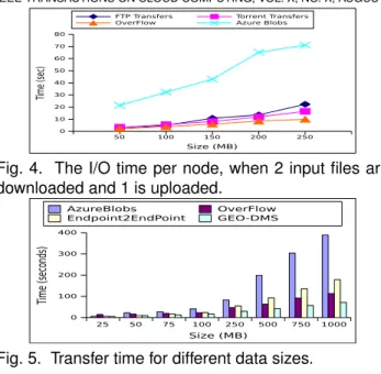
Fig. 4. The I/O time per node, when 2 input files are downloaded and 1 is uploaded.
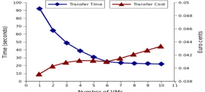
25 50 75 100 250 500 750 1000 Size (MB) 0 100 200 300 400 Time (seconds) AzureBlobs OverFlow Endpoint2EndPoint GEO-DMS
Fig. 5. Transfer time for different data sizes. 5.2 Evaluating the intra-site transfers
The first scenario measures the improvements brought to I/O-intensive applications by adaptively switching between transfer protocols. Multiple nodes read and produce files, concurrently accessing the data man-agement system to replicate (multicast) and transfer (pipeline) them within the deployment. We compare OverFlow with 2 other solutions: using the remote cloud storage (i.e., Azure Blobs[20]) as an intermediate and several static transfer mechanisms (e.g., FTP or Torrent). Figure 4 presents the average I/O time per node. We notice that the adaptive behaviour of our solution, which alternates the transfer strategies, leads to a 2x speedup compared to a static file handling and a 5x speedup compared to Azure Blobs. Local file management options (OverFlow, FTP, Torrent) are better than the remote cloud storage because they leverage deployment-locality by managing files within the compute nodes. Finally, our approach out-performs static FTP or Torrent, because it dynamically switches between them, i.e., use Torrent for multicast operations and FTP for direct transfers.
5.3 Evaluating the inter-sites transfers
Clouds lack proper support for inter-sites application data transfers. We compared our transfer/replication service with several state-of-the-art solutions adapted as placeholders: the Globus Online tool (which uses GridFTP as a server backend), the Azure Blobs cloud storage (used as an intermediate storage for passing data) and direct transfers between endpoints, denoted EndPoint2EndPoint. The results of this evaluation are shown in Figure 5. Azure Blobs is the slowest option with the transfer performed in 2 steps: a writing phase from the source node to the storage, followed by a read phase in which data is downloaded at destination. Despite the high latencies of the HTTP-based access, the cloud storage is the only option currently available by default. Globus Online, the state of the art alternative, lacks the cloud-awareness,
1 2 3 4 5 6 7 8 9 10 Time (minutes) 0 2000 4000 6000 8000 10000 12000 14000 16000 Thr oughput (MB/s) ShortestPath dynamic DirectLink ShortestPath static
a) The aggregation of throughput in time
5 10 15 20 25
Number of Nodes Used
0 2000 4000 6000 8000 10000 12000 14000 16000 Thr oughput (MB/s) ShortestPath dynamic DirectLink ShortestPath static
b) The throughput based on number of nodes
Fig. 6. The throughput between North EU and North US sites for different multi-route strategies, evaluated: a) in time, with a fixed number of node (25); b) based on multiple nodes, with a fix time frame (10 minutes) being more adequate for managing data collections of warehouses rather than application data exchanges. Finally, the EndPoint2EndPoint does not aggregate ex-tra bandwidth between datacenters implementing the transfers over the basic, but widely used, TCP client-server socket communication. Our approach reduces the transfer times with a factor of 5 over the cloud offering and with up to 50% over the other options. Budget-wise, these approaches do not incur the same costs: Azure Blobs charges extra cost for storage; the 1 node EndPoint2EndPoint cost/performance tradeoff is analyzed in Section 5.4; Globus Online incurs higher costs than OverFlow as it delivers lower performance with the same resource set.
Next, we consider a scenario in which additional sites are used as intermediate routing hops to transfer the data. For this experiment we considered that the service is available on nodes deployed across all the 6 US and EU sites. Figure 6 presents the evaluation of the proposed approach, described in Algorithm 1. We compare our solution with 3 other transfer strategies which schedule the transfer across multiple nodes – all using equal number of nodes. The first option, denoted DirectLink, considers only direct transfers between the source and destination datacenters, meaning that all nodes are allocated in these two sites. As this direct path might not be in fact the shortest one, the other strategies consider the shortest path computed using Dijkstra’s algorithm, which can span over multiple sites. The selection of the shortest path for routing the transfer can be done: 1) once, at the beginning of the transfer (this option is denoted ShortestPath static); or 2) regularly, based on a fresh view of the environment obtained from the Monitor Service (denoted ShortestPath dynamic).
In Figure 6 a) we present the cumulative through-put obtained with each strategy when scheduling 25 nodes. The shortest path strategy and our approach have similar performance for the first part of the transfer. This happens because our algorithm extends the shortest path strategy. The difference lays in the mechanisms for selecting alternative paths when the gain brought by a node along the initial path becomes smaller than switching to a new path (due to conges-tion). As a result, the improvement brought increases
IEEE TRANSACTIONS ON CLOUD COMPUTING, VOL. X, NO. X, AUGUST 2014 11
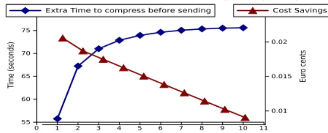
Fig. 7. The tradeoff between transfer time and cost for multiple VM usage (1 GB transferred from EU to US) with time, reaching 20% in the 10 minute window considered. Alternatively, selecting the routes with static strategies decreases the performance with time, thus being inefficient for Big Data. In Figure 6 b) we analyze the throughput when increasing the number of nodes. The goal is to understand how much data can be sent given a resource set and a timeframe (here 10 minutes). For small scenarios, all strategies perform roughly similar. However, for larger setups, our algorithm is capable to better schedule resource placement, which translates into higher throughput, in line with Big Data applications needs.
5.4 Efficient resource usage with the Cost
Esti-mator Service
Our next experiment focuses on the relation between price and the transfer efficiency. The cost estimator service maps the costs with the performance gains (i.e., speedup) obtained by the parallel transfer across intermediate nodes. As the degree of parallelism is scaled, we observe in Figure 7 a non-linear reduction for the transfer time. This demonstrates that each allocated node brings a lower performance gain as modeled in Equation 1. At the same time, the cost of the nodes remains the same, regardless of the efficiency of their usage. The time reduction obtained by using more nodes prevents the transfer cost to grow significantly, up to a certain point. This is the case in Figure 7 when using 3 to 5 VMs. Thus, despite paying for more resources the transfer time reduction obtained balances the cost. When scaling beyond this point, the performance gains per new nodes start to decrease which results in a price increase with the number of nodes. Looking at the cost/time ratio, an optimal point is found around 6 VMs for this case (the maximum time reduction for a minimum cost). However, depending on how urgent the transfer is, different transfer times can be considered accept-able. Having a service which is able to offer such a mapping between cost and transfer performance, enables applications to adjust the cost and resource requirements according to their needs and deadlines, while managing costs.
5.5 Evaluating the gains brought by the Smart
Compression Service
Sending data across sites is an expensive operation, both money- and time-wise. One of the functionalities
NUS EUS SUS WUS NEU
0 20 40 60 80 100 120 140 Time (second) Transfer time
Transfer time and Deduplication Checking Overhead Time
Fig. 8. The overhead of checking for deduplication on the remote site before sending the data
of this service is deduplication, by verifying on the remote sites whether (parts of) the data are already present and thus, avoid duplicate transfers. Perform-ing this checkPerform-ing adds an extra time, presented in Figure 8. The measurements are done for the scenario with 100 MB of data transferred from West EU. The overhead introduced by our service for the dedupli-cation check is small (∼5%), with only one call to the remote service. This observation and the possibility of fully eliminating the transfer make this service a viable option for inter-sites data management.
When avoiding transfers is not possible, the alter-native to reduce the costs is to compress the data. However, such an action increases the overall time to execute the operation, as depicted in Equations 5. On the other hand, it reduces the costs (Equation 6) involved in moving the data, considering that the outbound traffic is charged more than leasing VMs [19]. In Figure 9 we present the relation between the extra time needed to compress data and the cost savings. The results are computed as time and cost differences when compression is enabled / disabled. In this experiment, we consider that a protein data set of 800 MB is compressed at a speed of 5 MB/s, achieving a compression ratio of 50% (i.e., the data represents a protein set of the BLAST scientific work-flow [21]). Not only the transfer cost is reduced via compression, but the multi-route approach can also compensate through a higher parallelism degree for the compression. Using more resources decreases the transfer time, making the compression time dominant for the equivalent setup with replication enabled. Consequently, the “compute cost” component charged for the resource usage decreases without compression, compensating for the cost decrease in outbound traffic brought by compression. Hence, the service enables applications to identify and adopt one strategy or the other, according to their needs.
5.6 Impact of OverFlow for real-life workflows
Next, we evaluate the benefits of our approach for single and multiple datacenters workflows execution. 5.6.1 Single-site: MapReduce benchmarking
MapReduce [22] is one of the most wide-spread type of computation performed nowadays on the cloud, making it an interesting candidate to evaluate the impact of OverFlow. We propose the following ex-periment: we take an actual MapReduce engine (i.e.,
0 1 2 3 4 5 6 7 8 9 10 11 Number of VMs 55 60 65 70 75 Time (seconds) 0.01 0.015 0.02 Eur o cents
Fig. 9. The cost savings and the extra time required if data is compressed before sending
the Hadoop on Azure service [23], denoted HoA) and a general-purpose workflow engine (i.e., the open-source Microsoft Generic Worker [12], denoted GW) and run a typical WordCount MapReduce benchmark. We used an input of 650 MB data, processed in 2 setups: with 20 mappers (32 MB per job) and 40 mappers (16 MB per job); the number of reducers is 3 in both cases. The results, presented in Figure 10, show, as expected, that the specialized MapReduce tool is more efficient. The question is: can OverFlow improve the performance of a workflow engine compared to a MapReduce engine? To answer, we replaced the Azure Blob based storage of the Generic Worker with our approach (denoted GW++), and run the benchmark. We notice that GW++ achieves a 25% speedup com-pared to Hadoop, building on its protocol switching approach which enables to use the best local transfer option according to the data access pattern.
5.6.2 Single-site: BLAST - protein sequencing The next set of experiments focuses on the benefits that our approach can bring to a real-life scientific workflow – BLAST [21], which compares biologi-cal sequences to identify those that resemble. The workflow is composed of 3 types of jobs: a splitter for input partitioning (an 800 MB protein set), the core algorithm (i.e., the BLAST jobs) matching the partitions with reference values stored in 3 database files (the same for all jobs) and an assembler to aggre-gate the result. We show in Figure 11 the makespan of executing the BLAST analysis with the Generic Worker engine, using its default data management backend and our adaptive solution. We test both small and large files transfers, as increasing the number of jobs translates into smaller intermediate files. We also perform a broadcast, as the input database files (with a constant size of ∼1.6 GB) are disseminated to all jobs. We notice that protocol switching among these patterns pays off reducing to more than half the data management time.
5.6.3 Multi-site: A-Brain – searching for neuroimaging - genetic correlations
Finally, we present an evaluation of the time re-ductions obtained with the multi-route approach for wide-area transfers. We perform the evaluation for a real-life application, A-Brain, which makes joint genetic and neuro-imaging data analysis [24]. A-Brain has high resource requirements, which leads to its
Fig. 10. Map and Reduce times for WordCount (32 MB vs. 16 MB / map job).
25 BLAST jobs 50 BLAST jobs 100 BLAST jobs 0:00:00 0:30:00 1:00:00 1:30:00 GenericWorker - AzureBlobs GenericWorker-OverFlow Compute time
Fig. 11. The BLAST workflow makespan: the compute time is the same (marked by the horizontal line), the remaining time is the data handling
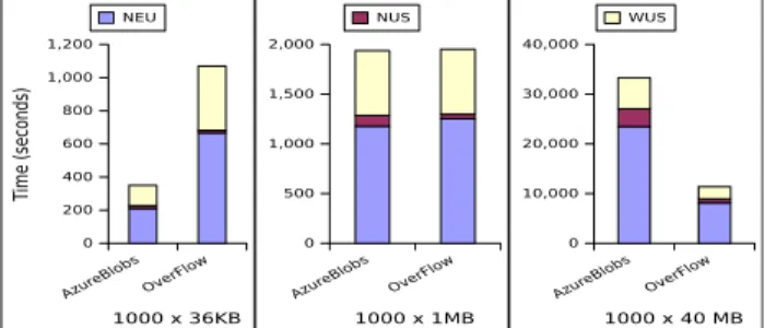
execution across 3 cloud datacenters. In this scenario, we focus on the transfer times of 1000 files of partial data, which are aggregated in one site to compute the final result. We compare OverFlow with the transfer done via Azure Blobs. The results are shown in Figure 12 for multiple file sizes, resulted from different input data sets and configurations. For small data sets (108 MB resulted from 3x1000x36KB files), the overhead introduced by our solution, due to the extra acknowl-edgements, makes the transfer less efficient. However, as the data size grows (120 GB), the total transfer time is reduced by a factor of 3.
6
R
ELATEDW
ORKThe handiest option for handling data distributed across several datacenters is to rely on the existing cloud storage services (e.g., Amazon S3, Azure Blobs)). This approach allows to transfer data between arbi-trary endpoints via the cloud storage and it is adopted by several systems in order to manage data move-ments over wide-area networks [2]. Typically, they are not concerned by achieving high throughput, nor by potential optimizations, let alone offer the ability to support different data services (e.g., geographically distributed transfers). Our work aims is to specifically address these issues.
Besides storage, there are few cloud-provided services that focus on data handling. Some of them use the geographical distribution of data to reduce latencies of data transfers. Amazon’s CloudFront [25], for in-stance, uses a network of edge locations around the world to cache copy static content close to users. The goal here is different from ours: this approach is meaningful when delivering large popular objects to many end users. It lowers the latency and allows
IEEE TRANSACTIONS ON CLOUD COMPUTING, VOL. X, NO. X, AUGUST 2014 13
AzureBlobsOverFlow
1000 x 36KB 0 200 400 600 800 1,000 1,200 Time (seconds) NEU
AzureBlobs OverFlow
1000 x 1MB 0 500 1,000 1,500 2,000 NUS
AzureBlobs OverFlow
1000 x 40 MB 0 10,000 20,000 30,000 40,000 WUS
Fig. 12. A-Brain execution times across 3 sites, using Azure Blobs and OverFlow as backends, to transfer data towards the NUS datacenter
high, sustained transfer rates. Similarly, [26] and [27] considered the problem of scheduling data-intensive workflows in clouds assuming that files are replicated in multiple execution sites. These approaches can reduce the makespan of the workflows but come at the cost and overhead of replication. In contrast, we extend this approach to exploit also the data access patterns and leverage a cost/performance tradeoff to allow per file optimizations of transfers.
The alternative to the cloud offerings are the trans-fer systems that users can choose and deploy on their own, which we generically call user-managed solutions. A number of such systems emerged in the context of the GridFTP [28] transfer tool, initially developed for grids. In these private infrastructures, informa-tion about the network bandwidth between nodes as well as the topology and the routing strategies are publicly available. Using this knowledge, transfer strategies can be designed for maximizing certain heuristics [29]; or the entire network of nodes across all sites can be viewed as a flow graph and the transfer scheduling can be solved using flow-based graph algorithms [30]. However, in the case of public clouds, information about the network topology is not available to the users. One option is to profile the performance. Even with this approach, in order to apply a flow algorithm the links between all nodes need to be continuously monitored. Such monitoring would incur a huge overhead and impact on the transfer. Among these, the work most comparable to ours is Globus Online [31], which provides high performance file transfers through intuitive web 2.0 interfaces, with support for automatic fault recovery. However, Globus Online only performs file transfers between GridFTP instances, remains unaware of the environment and therefore its transfer optimizations are mostly done statically. Several extensions brought to GridFTP allow users to enhance transfer perfor-mance by tuning some key parameters: threading in [32] or overlays in [29]. Still, these works only focus on optimizing some specific constraints and ignore others (e.g., TCP buffer size, number of outbound requests). This leaves the burden of applying the most appropriate settings effectively to users. In contrast, we propose a self-adaptive approach through a simple and transparent interface, that doesn’t require addi-tional user management.
Other approaches aim at improving the throughput by exploiting the network and the end-system paral-lelism or a hybrid approach between them. Building on the nework parallelism, the transfer performance can be enhanced by routing data via intermediate nodes chosen to increase aggregate bandwidth. Multi-hop path splitting solutions [29] replace a direct TCP connection between the source and destination by a multi-hop chain through some intermediate nodes. Multi-pathing [33] employs multiple indepen-dent routes to simultaneously transfer disjoint chunks of a file to its destination. These solutions come at some costs: under heavy load, per-packet latency may increase due to timeouts while more memory is needed for the receive buffers. On the other hand, end-system parallelism can be exploited to improve uti-lization of a single path by means of parallel streams [31] or concurrent transfers [34]. However, one should also consider system configuration since specific local constraints (e.g., low disk I/O speeds or over-tasked CPUs) may introduce bottlenecks. One issue with all these techniques is that they cannot be ported to the clouds, since they strongly rely on the underlying network topology, unknown at the user-level.
Traditional techniques commonly found in scientific computing, e.g. relying on parallel file systems are not always adequate for processing big data on clouds. Such architectures usually assume high-performance communication between computation nodes and stor-age nodes (e.g. PVFS [35], Sector [36]). This assump-tion does not hold in current cloud architectures, which exhibit much higher latencies between compute and storage resources within a site, and even higher ones between datacenters.
7
C
ONCLUSIONThis paper introduces OverFlow, a data management system for scientific workflows running in large, ge-ographically distributed and highly dynamic envi-ronments. Our system is able to effectively use the high-speed networks connecting the cloud datacen-ters through optimized protocol tuning and bottleneck avoidance, while remaining non-intrusive and easy to deploy.Currently, OverFlow is used in production on the Azure Cloud, as a data management backend for the Microsoft Generic Worker workflow engine.
Encouraged by these results, we plan to further investigate the impact of the metadata access on the overall workflow execution. For scientific workflows handling many small files, this can become a bot-tleneck, so we plan to replace the per site metadata registries with a global, hierarchical one.Furthermore, an interesting direction to explore is the closer integra-tion between OverFlow and an ongoing work [37] on handling streams of data in the cloud, as well as other data processing engines.To this end, an extension of the semantics of the API is needed.
![Fig. 2. Architecture of the adaptive protocol-switching file management system [6]. Operations for transferring files between VMs: upload (1), download (2,3,4).](https://thumb-eu.123doks.com/thumbv2/123doknet/12397351.331733/6.850.63.407.59.322/architecture-adaptive-protocol-switching-management-operations-transferring-download.webp)