CODEN STJSAO ISSN 0562-1887
ZX470/1252 UDK 62(05)=862=20=30
Dynamic simulations of solar combisystems integrating a
seasonal sorption storage: Influence of the combisystem
configuration
Samuel HENNAUT1), Sébastien THOMAS1), Elisabeth DAVIN1), Alexandre SKRYLNYK2), Marc FRERE2) and Philippe ANDRE1) 1) University of Liège, Building Energy
Monitoring and Simulation Av. de Longwy 185, B-6700 Arlon,
Belgium
2) University of Mons, Energy Research Center
Bd. Dolez 31, B-7000 Mons, Belgium shennaut@ulg.ac.be Keywords Seasonal storage Solar combisystem Bromide Stontium Adsorption Ključne riječi Seasonal storage Solar combisystem Bromide Stontium Adsorption Primljeno (Received): 20xx-xx-xx Prihvaćeno (Accepted): 20xx-xx-xx Abstract
This paper focuses on the sizing of solar combisystems with adsorption seasonal storage to target autonomous solar space heating. Two main configurations of the combisystem are simulated, including one or two tanks. The influence of the seasonal storage on the sizing of the tanks is also discussed. The analysis is conducted in simulation using the TRNSYS program. Results show that performances of the system with two tanks are better (2 to 4 % with seasonal storage) but some improvements should be possible for the single tank configuration. The sizing of the sensible storage is nearly independent of the solar collectors area if there is a seasonal storage. The sensible storage size increase with the collectors area without adsorption storage.
Sažetak
This paper focuses on the sizing of solar combisystems with adsorption seasonal storage to target autonomous solar space heating. Two main configurations of the combisystem are simulated, including one or two tanks. The influence of the seasonal storage on the sizing of the tanks is also discussed. The analysis is conducted in simulation using the TRNSYS program. Results show that performances of the system with two tanks are better (2 to 4 % with seasonal storage) but some improvements should be possible for the single tank configuration. The sizing of the sensible storage is nearly independent of the solar collectors area if there is a seasonal storage. The sensible storage size increase with the collectors area without adsorption storage.
1. Introduction
In temperate or cold climate, seasonal thermal energy storage is necessary to reach a 100 % solar fraction for space heating. Using reaction enthalpy of sorption phenomenon is an interesting way to store thermal energy. This kind of storage is particularly well suited for long-term storage because of its high storage density and of the absence of almost all thermal losses[1].
Previous researches [2, 3] have shown that autonomous solar space heating systems could be designed using this seasonal storage technology coupled to a ground heat exchanger used as a low temperature source. In these previous works, the combisystem was
designed arbitrarily using two tanks, one for space heating (SH) and one for domestic hot water (DHW). This design identifies more easily the different heat flows associated to both purposes.
This paper deals with the analysis, by simulation, of the influence of the solar combisystem design on the complete system performances. The influence of the number of tanks and of the volume of the tanks is assessed. Additionally, the performance of these systems is evaluated without seasonal storage to quantify the influence of the storage utilization on the sizing of the system.
Symbols/Oznake
E - annual final energy demand, kWh
- annual final energy demand Subscripts/Indeksi
Fsav, therm
- fractional thermal energy savings
- fractional thermal energy savings boiler,aux
- auxiliary boiler - auxiliary boiler
Q - annual thermal energy load, kWh
- annual thermal energy load boiler,ref
- reference system boiler - reference system boiler Pmax
- Power available, kW
- Power available DHW
- for domestic hot water production - for domestic hot water production
(g)
- gaseous - gaseous
Greek letters/Grčka slova (s)
- solid - solid
Hr
- heat of reaction, J
- heat of reaction SH
- for space heating - for space heating
η - mean annual efficiency
- mean annual efficiency TOT
- total, for the global system - total, for the global system
2. Simulated systems
The simulated system includes the building, the sorption storage reactor and the solar combisystem. The dynamics simulations are realized with TRNSYS [4].
2.1. Seasonal storage
In the simulated systems the seasonal storage is carried out by a closed adsorption system using SrBr2/H2O as working pair, according to the following reaction: ) ( 2 ) ( 2 2 ) ( 2 2.6H Os Hr SrBr..H Os 5H Og SrBr (1)
The working of the storage apparatus briefly described hereafter is more detailed in [3] and [5]. The storage plant is composed of a chemical reactor containing the adsorbent and of a tank used to store the condensed adsorbate. Both are linked and a valve allows or prevents mass transfer between the two parts when necessary. During summer, solar heat is provided to the reactor to desorb water vapor which is condensed in the storage tank. During winter, the stored water is evaporated at low temperature level and adsorbed to the salt. Adsorption reaction heat is then released for SH. The evaporation and condensation of the adsorbate is supposed to be achieved using a ground heat exchanger (which is not simulated). The adsorbate evaporation and condensation temperatures are supposed to be constant: respectively 5°C and 20°C.
The model used for the chemical reactor is based on the “Detailed Modelling Approach” described in [5]. It computes dynamic energy and mass balances of the reactor and includes some kinetic aspects of the
reaction. Currently, this model is not experimentally validated yet.
2.2. Reference building
The simulated building, used in previous studies [2, 3, 5], is a “low-energy” single-family house. Its heating area is 100 m² shared between two floors and 40 m² of the roof are facing South with a slope of 40°. Set point temperatures for SH are permanently 20°C and 18°C respectively for the ground floor and the first floor. Uccle, in Belgium, is chosen as climate. The annual building heating demand is around 4200 kWh for SH and 2710 kWh for DHW.
2.3. Combisystems: 2 configurations
Two main configurations of the combisystem are considered. The first configuration uses two storage tanks, one for SH and another for DHW. The tank dedicated to SH is fed primarily by the solar loop. The second configuration includes only one tank for both purposes and DHW is produced using an external heat exchanger. For each configuration, outlets are located at the top of the tank both for SH and DHW. These two configurations are respectively illustrated in Figure 1 and Figure 2.
For all simulations realised for this study, the “space heating period” is considered to run from 1st of October to 30th of April. During this period, the maximum temperature allowed in the tank is fixed to 95°C (even this temperature is rarely reached).
Figure 1. Configurations of the solar combisystem designed with 2 tanks Slika 1. Configurations of the solar combisystem designed with 2 tanks
Figure 2. Configurations of the solar combisystem designed with 1 tank Slika 2. Configurations of the solar combisystem designed with 1 tank
Outside this period, the building is not heated and the solar heat can be stored thermochemically if there is no need for DHW production. This part of the year running from 1st of May to 30th of September is consequently called the “storage period” for which the tank dedicated to SH (in the first configuration) is not used and the maximum temperature in the other (or single) tank is reduced to 75°C to increase solar heat available for seasonal storage.
The simulated solar collectors are flat plate collectors with high efficiency values which are targeted into the frame of this research project:
Optical efficiency (a0) = 0,80;
Linear loss coefficient (a1) = 1,57 W/(m²K)
Quadratic loss coefficient (a2) = 0,0072
W/(m²K²)
The emission device chosen for SH is a water-based floor heating fed at maximum 35°C. For both configurations, two instantaneous auxiliary heaters are used. One for SH which is added between the tank and the floor heating to reheat the water leaving the tank (or the storage reactor) to 35°C if the set point is not reached in the building with lower temperature and another for DHW which guarantees a temperature of 45°C for DHW users.
2.4. Seasonal storage integration
The storage reactor is integrated in the solar combisystem, both in the solar loop and in the SH distribution system (see Figures 1 and 2). The thermochemically stored heat is only dedicated to the building heating. It’s not used for DHW production because of the temperature level which can be reached using the chosen adsorbent/adsorbate couple. During winter, the seasonal storage is used as an instantaneous auxiliary heater for SH. The water leaving the tank is reheated by the thermochemical reactor if the temperature of the reactor is higher. Otherwise, the tank water is directly provided to the emission system.
The storage reactor is composed of one big module containing the totality of the reactant salt and achieving only one cycle per year (charging during summer and discharging during winter). If the salt is completely desorbed before the end of the storage period, the reactor is used as a sensible storage medium until the beginning of the heating period.
3. Methodology
Both configurations of the combisystem described above are compared, with and without seasonal storage. For each configuration, different values were tested for the following parameters:
Solar collectors area
Volume of the tanks: DHW and SH or a single tank
Adsorbent mass
The tested values are summed up in Table 1. Performances of the simulated systems are evaluated using the “fractional thermal energy savings” indicator (fsav,therm) developed in the framework of IEA-SHC Task
26 [6]: ref boiler ref boiler aux boiler aux boiler ref aux boiler therm sav Q Q E E F , , , , , , 1 1 (2)
Fsav,therm is computed for DHW production (Fsav,DHW),
for the SH energy consumption (Fsav,SH) and for the
global system (Fsav,TOT). The reference consumption
(Qboiler,ref) for the DHW and SH are respectively around
2710 and 4200 kWh. The same efficiency ( is considered for the reference system and for the auxiliary heaters, i.e. 85 %. For the global system, the reference consumption is the sum of the consumptions for DHW and SH. This indicator will help to compare the two configurations performance but also to discuss the system sizing methodology with and without seasonal storage.
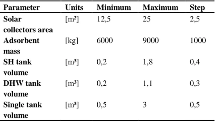
Table 1. Parameters variations. Tablica 1. Parameters variations.
Parameter Units Minimum Maximum Step Solar collectors area [m²] 12,5 25 2,5 Adsorbent mass [kg] 6000 9000 1000 SH tank volume [m³] 0,2 1,8 0,4 DHW tank volume [m³] 0,2 1,1 0,3 Single tank volume [m³] 0,5 3 0,5
4. Results and analysis
4.1. Without seasonal storage
If the thermochemical seasonal storage is not used, both configurations reach almost the same performances for the complete system, with a small advantage (less than 1%) for the two-tanks system. This observation is illustrated on Figure 3.
On this figure for each collectors area tested, the Fsav,TOT for the best case and the volume of the
corresponding tank are plotted. Here, the best case is defined as the case allowing to reach, with the smallest sensible storage volume, at least the maximum value
computed for Fsav,TOT minus 1%. For these best cases,
the volumes of the tank are quite close for both configurations.
Figure 3. Fsav,TOT and tank volume for best cases without seasonal storage
Slika 3. Fsav,TOT and tank volume for best cases without seasonal storage
4.2. With seasonal storage
If the solar system integrates the thermochemical reactor, the advantage of the first configuration (2 tanks) becomes greater. For large collectors area, using two
tanks increases the Fsav,TOT by around 4 % compared to
the configuration with a single tank.
Figure 4. Fsav,TOT and tank volume for best cases with seasonal storage
With seasonal storage, the best case is defined as the case allowing to reach at least the maximum value computed for Fsav,TOT minus 1% with the smallest
adsorbent mass (among cases with the smallest adsorbent mass, the one with the smallest sensible storage volume is chosen). These best cases are shown on Figure 4 for each collector area. For the configuration with one tank, the masses of adsorbent computed are lower than for the system with two tanks, but the Fsav,TOT values are also lower. The results show
that with two tanks, for an equal mass of salt, results are better (up to 2%) than with one tank. In most cases, the configuration has little influence on the necessary volume for the sensible storage.
The comparison of the Fsav computed for the best
cases with and without seasonal storage shows that, for
identical areas of collectors, the thermochemical storage allows saving between 30 and 40 %. It’s also shown that the sizing of the storage tank won’t be the same if some seasonal storage occurs. The Figure 3 shows that it’s interesting to increase the sensible storage volume when the collectors’ area grows up, if there is no seasonal storage. At the opposite, with seasonal storage, a tank
volume around 1 m³ allows to reach the best performance regardless of collectors’ area (see Figure 4).
Some of the best cases selected don’t allow to have an autonomous SH system with solar energy (Fsav,SH>0,99). But if the best cases are selected among
those allowing to reach the autonomy for SH, the conclusions are similar.
4.3. Case study: 1.5 m³ sensible storage, 22.5 m² collectors and 7000 kg adsorbent
Both configurations are studied in details for a fixed storage volume (1.5 m³) in this section. For the single-tank configuration, the sensible storage is made up of 0.5 m³ for DHW and 1 m³ dedicated to SH. The performances of the global system and of the SH are illustrated on Figure 5, for different collectors areas and a variable mass of adsorbent. It’s shown that, in most cases, the performances are slightly better with two tanks than with one.
Figure 5. Comparison of the performance of the two configurations with a sensible storage of 1.5 m³, for the global system (on
the left) and for SH only (on the right)
Slika 5. Comparison of the performance of the two configurations with a sensible storage of 1.5 m³, for the global system (on the left) and for SH only (on the right)
Some explanations can be found by the analysis of the following particular case: a comparison of the energy balances is done for a solar system with 1.5 m³ of sensible storage, 22.5 m² of collectors and 7000 kg of adsorbent. In this case, the lower performance of the single-tank configuration can be explained by the following observations and assumptions.
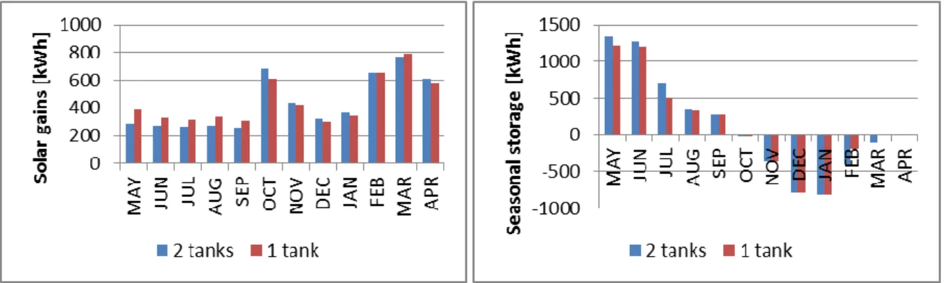
During summer, there are more solar gains in the single storage tank (see Figure 6 left). We suppose that in this configuration, the single tank is too large for summer operation which reduces solar energy available for the seasonal storage (see Figure 6 right). Stored heat becomes insufficient at the end of winter (see Figure 6 right and 7 left). In the two-tanks configuration, only the DHW tank is used during summer,
which makes more solar heat available for seasonal storage.
During winter, the solar gains in the single tank are lower (see Figure 6 left) probably because it is hotter than the DHW tank in the single-tank configuration.
An increasing consumption of the auxiliary heating energy used for DHW is observed in February and March (See Fig. 7 right). It seems that at the end of the SH period, when the thermochemical storage is “empty”, the important flow rate in the single tank reduces the stratification in the tank and consequently the performance of the DHW production.
Figure 6. Solar gains in the tanks (on the left) and seasonal thermochemical storage (on the right) Slika 6. Solar gains in the tanks (on the left) and seasonal thermochemical storage (on the right)
Figure 7. Auxiliary heating needs for SH (on the left) and for DHW (on the right) Slika 7. Auxiliary heating needs for SH (on the left) and for DHW (on the right)
5. Conclusions and outlook
The results show that the performances of both configurations are almost the same without seasonal storage. If the thermochemical storage is used, the configuration with two tanks allows increasing the fractional thermal energy savings of the complete system from 94 to 98 % in the best case illustrated. For the configuration with a single tank, a plateau seems to be reached for a Fsav around 94 %.
This conclusion wasn’t expected. Actually, the objective of using one tank instead of two was first to reduce thermal losses through the wall of the tanks and to increase the thermal performances of the system by this way. The high insulation simulated for the tanks (0.53 W/(m².K)) has probably reduces this impact on the system behaviour. Nevertheless, the single tank solution allows reducing the bulk of the system and the investment cost. Some modification may also be investigated to increase the performances of this configuration. For instance, to reduce the maximal temperature in the tank during summer should make more solar heat available for seasonal storage while ensuring the solar production of DHW.
Another issue of the configuration with a single tank is the production of the DHW. The simulated external unit, requires the use of an instantaneous auxiliary heating which is difficult to provide without connexion to the natural gas network. Additionally, the wish to heat the building with renewable energy only doesn’t allow to heat the single storage tank with non-renewable energy sources.
If the sizing of the sensible storage seems to be very close for both configurations, some differences appear if we compare the systems with or without seasonal storage. As expected, for system without seasonal storage, it is interesting to increase the sensible storage capacity with the collectors area. But if the storage reactor is used, the sensible storage has to be around 1m³.
Future work will focus on new combisystem configurations, especially to improve the performance of the single tank configuration. The modification of the position of the outlet for space heating could also increase the performance of the system. Future works will study the influence of the position of this outlet but also the influence of the choice of an internal heat
exchanger which should reduce internal water flows in the tank.
Acknowledgements
Research presented in this paper is conducted in the SOLAUTARK project with the following partner’s: ESE, ArcelorMittal Liège R&D, Atelier architecture Ph. Jaspard, ULB, CTIB, M5, UMons, and ULg. This project is funded by the Plan Marshall of the Walloon Region.
REFERENCES
[1] K. E. N'Tsoukpoe, H. Liu, N. Le Pierrès, and L. Luo, "A review on long-term sorption solar energy storage," Renewable and Sustainable
Energy Reviews, vol. 13, pp. 2385-2396, 2009.
[2] S. Hennaut, S. Thomas, P. Andre, E. Courbon, T. Berigot (Le), and M. Frère, "Pré-dimensionnement par simulations dynamiques d'un réacteur de stockage thermochimique assurant l'autonomie d'un système solaire combiné," presented at the Congrès Français de Thermique 2011 - Energie Solaire et Thermique, Perpignan, 2011.
[3] S. Hennaut, S. Thomas, E. Davin, and P. Andre, "DYNAMIC SIMULATION OF
RESIDENTIAL BUILDINGS WITH
SEASONAL SORPTION STORAGE OF
SOLAR ENERGY– PARAMETRIC
ANALYSIS," presented at the ISES solar world congress 2011, Kassel, Germany, 2011. [4] "TRNSYS," 17.00.0019 ed. Madison,
Wisconsin, USA: Solar Energy Laboratory - University of Wisconsin, 2010.
[5] A. Skrylnyk, E. Courbon, M. Frère, S. Hennaut, P. Andre, P. Sun, and G. Descy, "Modelling of a solar thermo-chemical system for energy storage in buildings," presented at the Innostock 2012 - The 12th International Conference on Energy Storage, Lleida, Spain, 2012.
[6] T. Letz, "Validation and background information on the FSC procedure," IEA SHC2002.