ScienceDirect
Available online at Available online at www.sciencedirect.comwww.sciencedirect.com
ScienceDirect
Procedia Manufacturing 00 (2017) 000–000
www.elsevier.com/locate/procedia
* Paulo Afonso. Tel.: +351 253 510 761; fax: +351 253 604 741
E-mail address: [email protected]
2351-9789 © 2017 The Authors. Published by Elsevier B.V.
Peer-review under responsibility of the scientific committee of the Manufacturing Engineering Society International Conference 2017.
Manufacturing Engineering Society International Conference 2017, MESIC 2017, 28-30 June
2017, Vigo (Pontevedra), Spain
Costing models for capacity optimization in Industry 4.0: Trade-off
between used capacity and operational efficiency
A. Santana
a, P. Afonso
a,*, A. Zanin
b, R. Wernke
ba University of Minho, 4800-058 Guimarães, Portugal bUnochapecó, 89809-000 Chapecó, SC, Brazil
Abstract
Under the concept of "Industry 4.0", production processes will be pushed to be increasingly interconnected, information based on a real time basis and, necessarily, much more efficient. In this context, capacity optimization goes beyond the traditional aim of capacity maximization, contributing also for organization’s profitability and value. Indeed, lean management and continuous improvement approaches suggest capacity optimization instead of maximization. The study of capacity optimization and costing models is an important research topic that deserves contributions from both the practical and theoretical perspectives. This paper presents and discusses a mathematical model for capacity management based on different costing models (ABC and TDABC). A generic model has been developed and it was used to analyze idle capacity and to design strategies towards the maximization of organization’s value. The trade-off capacity maximization vs operational efficiency is highlighted and it is shown that capacity optimization might hide operational inefficiency.
© 2017 The Authors. Published by Elsevier B.V.
Peer-review under responsibility of the scientific committee of the Manufacturing Engineering Society International Conference 2017.
Keywords: Cost Models; ABC; TDABC; Capacity Management; Idle Capacity; Operational Efficiency 1. Introduction
The cost of idle capacity is a fundamental information for companies and their management of extreme importance in modern production systems. In general, it is defined as unused capacity or production potential and can be measured in several ways: tons of production, available hours of manufacturing, etc. The management of the idle capacity
Procedia Manufacturing 29 (2019) 96–104
2351-9789 © 2019 The Authors. Published by Elsevier B.V.
This is an open access article under the CC BY-NC-ND license (https://creativecommons.org/licenses/by-nc-nd/4.0/) Selection and peer-review under responsibility of the organizing committee of SHEMET 2019.
10.1016/j.promfg.2019.02.111
10.1016/j.promfg.2019.02.111 2351-9789
© 2019 The Authors. Published by Elsevier B.V.
This is an open access article under the CC BY-NC-ND license (https://creativecommons.org/licenses/by-nc-nd/4.0/) Selection and peer-review under responsibility of the organizing committee of SHEMET 2019.
Available online at www.sciencedirect.com
ScienceDirect
Procedia Manufacturing 00 (2018) 000–000
www.elsevier.com/locate/procedia
2351-9789 © 2018 The Authors. Published by Elsevier B.V.
This is an open access article under the CC BY-NC-ND license (https://creativecommons.org/licenses/by-nc-nd/4.0/) Selection and peer-review under responsibility of the organizing committee of SHEMET 2019.
18th International Conference on Sheet Metal, SHEMET 2019
Prediction of cracks within cones processed by
single point incremental forming
Ehssen Betaieb
a*, Sibo Yuan
a, Carlos Felipe Guzman
b, Laurent Duchêne
a, Anne-Marie
Habraken
aaUniversity of Liège, ArGEnCo dpt, MSM team, 9 Allée de la Découverte, 4000 Liège
bDepartamento de Ingeniería en Obras Civiles, Universidad de Santiago de Chile, Av. Ecuador 3659, Santiago, Chile
Abstract
Plane stress tests such as tensile tests on smooth and notched samples as well as shear tests are used to identify the set of material parameters associated with two damage models: a micromechanically-based Gurson model and a continuum Lemaitre and Chaboche model. Finite element simulations and inverse modelling are applied on these tests to characterize the mechanical behavior of a DC01 steel sheet. The capabilities of these two damage models to predict the maximum wall angle before failure of cones formed by single point incremental forming are analyzed, showing that the Lemaitre and Chaboche model appears to be more reliable when applied on this steel sheet.
© 2018 The Authors. Published by Elsevier B.V.
This is an open access article under the CC BY-NC-ND license (https://creativecommons.org/licenses/by-nc-nd/4.0/) Selection and peer-review under responsibility of the organizing committee of SHEMET 2019.
Keywords: GTN model; Lemaitre model; SPIF; FE simulation 1. Introduction
Incremental sheet forming (ISF) refers to a type of forming process where the deformation is localized in a small zone and is applied by repeated contact between a tool and a clamped sheet metal. One of the most prominent characteristics of ISF is that the final part is almost entirely defined by the CAD-CAM instructions, requiring minimal specialized tooling. Hence, ISF stands as a remarkable option to deep drawing or stamping, being particularly suitable
* Corresponding author.
E-mail address: [email protected]
2 Ehssen Betaieb / Procedia Manufacturing 00 (2018) 000–000
for rapid prototyping and small batch productions. One variant of ISF is the single point incremental forming (SPIF), which is the main focus of this paper. SPIF is the simplest version of ISF, and it is characterized by a single forming tool which incrementally deforms a clamped sheet metal. Several review papers have addressed the latest developments around SPIF, e.g. Duflou et al. 2017 [1].
One of the remarkable features of SPIF is the formability, which is exceptionally high for a sheet metal process [1]. Researchers have undergone several studies to analyze this complex phenomenon, due to the localized stress state and the cyclic strain path induced by the tool. It has been shown that the classical forming limit diagram (FLD) underestimates failure strain in SPIF, with a process achieving strains closer to the forming fracture limit [1] or even higher [2].
Despite different researches on the formability characteristics of SPIF, the damage mechanisms leading to material failure are not totally well understood. In this respect, the literature offers some examples of finite element analysis with damage models. For instance, Malhotra et al. [3] used the Xue damage model [4], predicting faster damage accumulation in SPIF than in deep drawing [3]. However, fracture in SPIF is delayed because the plastic strain in the piece is distributed more evenly in ISF than in deep drawing.
The Gurson-Tvergaard-Needleman (GTN) model [5,6] is one of the most widely used damage models applied to ductile fracture. Its use in SPIF simulations is, nevertheless, not widespread. Li et al. [7] used the GTN model with a Hill '48 anisotropic matrix to predict failure in a SPIF cone. The material parameters were identified using a tensile test in three orthotropic directions. Gatea et al. [9] used a GTN model extended to shear to predict failure in a truncated SPIF cone and pyramid of pure titanium sheets. Guzman et al. [8] also analyzed the results of the GTN model extended to shear but applied on a DC01 steel sheet and a cone shape. It was concluded that this extended GTN model underestimates the maximum wall angle, due to an imprecise coalescence modeling. New simulations of this case were described in [8] where this GTN model was coupled with the physically-based Thomason criterion and lead to better results than the classical coalescence model proposed by Tvergaard and Needleman [10]. However, the damage predictions during SPIF were still far from the experimental observations. In a subsequent paper, the authors further explained this behavior and attributed the inaccurate results to inner limitations of the GTN model, which can also explain why the Xue damage model behaves better for SPIF Finite Element (FE) analyses [8].
Another popular damage model, the Lemaitre model [11], has been scarcely used in the SPIF FE context. For instance, Hapsari et al. [12] performed an identification of the damage parameters using the micro-SPIF process variant. The parameters were validated with force measurements in a truncated pyramid of copper alloy. Kumar et al. [13] coupled the Johnson-Cook model with the Lemaitre model to predict the behavior of an aluminum alloy in truncated cones.
In the present study, both the GTN and the Lemaitre damage approaches are compared in their ability to predict the damage evolution in SPIF. The paper is organized as follows. Section 2 presents the experiments used to characterize the plastic and damage behavior of the material. The SPIF process parameters are also briefly described. Section 3 shortly summarizes the constitutive models, the GTN and Lemaitre models. The material parameters used in the Gurson and Lemaitre model, and the comparisons between the numerical and the experimental results under different triaxialities, are presented in Section 4. The application of these two models for SPIF FE simulations and the discussions of the obtained results are exhibited in Section 5. Finally, some concluding remarks are synthetized in Section 6.
2. Experiments
A DC01 steel sheet of 1.0 mm in thickness has been selected. Its plastic behavior, including anisotropy and hardening, was characterized by an experimental campaign involving tensile tests, monotonic and cyclic shear tests performed in three orthogonal directions to the rolling direction (RD). Digital Image Correlation (DIC) was used to extract experimental displacements and strain fields. The DC01 presents some anisotropy as confirmed by its Lankford coefficients (r0=1.513, r45=1.141, r90=1.854). However, as shown in [18] the stress-strain curves in RD and transversal direction are very close, while the curve at the 45° direction is slightly lower than the other ones. The damage behavior was studied using another experimental campaign, with different geometries (notched and shear specimens) shown in Fig. 1. FE meshes used to simulate these tests were chosen after a convergence analysis. They are presented in Fig. 1, while experimental Force-displacement curves are presented in Fig. 4, together with numerical results.
Ehssen Betaieb et al. / Procedia Manufacturing 29 (2019) 96–104 97
ScienceDirect
Procedia Manufacturing 00 (2018) 000–000
www.elsevier.com/locate/procedia
2351-9789 © 2018 The Authors. Published by Elsevier B.V.
This is an open access article under the CC BY-NC-ND license (https://creativecommons.org/licenses/by-nc-nd/4.0/) Selection and peer-review under responsibility of the organizing committee of SHEMET 2019.
18th International Conference on Sheet Metal, SHEMET 2019
Prediction of cracks within cones processed by
single point incremental forming
Ehssen Betaieb
a*, Sibo Yuan
a, Carlos Felipe Guzman
b, Laurent Duchêne
a, Anne-Marie
Habraken
aaUniversity of Liège, ArGEnCo dpt, MSM team, 9 Allée de la Découverte, 4000 Liège
bDepartamento de Ingeniería en Obras Civiles, Universidad de Santiago de Chile, Av. Ecuador 3659, Santiago, Chile
Abstract
Plane stress tests such as tensile tests on smooth and notched samples as well as shear tests are used to identify the set of material parameters associated with two damage models: a micromechanically-based Gurson model and a continuum Lemaitre and Chaboche model. Finite element simulations and inverse modelling are applied on these tests to characterize the mechanical behavior of a DC01 steel sheet. The capabilities of these two damage models to predict the maximum wall angle before failure of cones formed by single point incremental forming are analyzed, showing that the Lemaitre and Chaboche model appears to be more reliable when applied on this steel sheet.
© 2018 The Authors. Published by Elsevier B.V.
This is an open access article under the CC BY-NC-ND license (https://creativecommons.org/licenses/by-nc-nd/4.0/) Selection and peer-review under responsibility of the organizing committee of SHEMET 2019.
Keywords: GTN model; Lemaitre model; SPIF; FE simulation 1. Introduction
Incremental sheet forming (ISF) refers to a type of forming process where the deformation is localized in a small zone and is applied by repeated contact between a tool and a clamped sheet metal. One of the most prominent characteristics of ISF is that the final part is almost entirely defined by the CAD-CAM instructions, requiring minimal specialized tooling. Hence, ISF stands as a remarkable option to deep drawing or stamping, being particularly suitable
* Corresponding author.
E-mail address: [email protected]
Available online at www.sciencedirect.com
ScienceDirect
Procedia Manufacturing 00 (2018) 000–000
www.elsevier.com/locate/procedia
2351-9789 © 2018 The Authors. Published by Elsevier B.V.
This is an open access article under the CC BY-NC-ND license (https://creativecommons.org/licenses/by-nc-nd/4.0/) Selection and peer-review under responsibility of the organizing committee of SHEMET 2019.
18th International Conference on Sheet Metal, SHEMET 2019
Prediction of cracks within cones processed by
single point incremental forming
Ehssen Betaieb
a*, Sibo Yuan
a, Carlos Felipe Guzman
b, Laurent Duchêne
a, Anne-Marie
Habraken
aaUniversity of Liège, ArGEnCo dpt, MSM team, 9 Allée de la Découverte, 4000 Liège
bDepartamento de Ingeniería en Obras Civiles, Universidad de Santiago de Chile, Av. Ecuador 3659, Santiago, Chile
Abstract
Plane stress tests such as tensile tests on smooth and notched samples as well as shear tests are used to identify the set of material parameters associated with two damage models: a micromechanically-based Gurson model and a continuum Lemaitre and Chaboche model. Finite element simulations and inverse modelling are applied on these tests to characterize the mechanical behavior of a DC01 steel sheet. The capabilities of these two damage models to predict the maximum wall angle before failure of cones formed by single point incremental forming are analyzed, showing that the Lemaitre and Chaboche model appears to be more reliable when applied on this steel sheet.
© 2018 The Authors. Published by Elsevier B.V.
This is an open access article under the CC BY-NC-ND license (https://creativecommons.org/licenses/by-nc-nd/4.0/) Selection and peer-review under responsibility of the organizing committee of SHEMET 2019.
Keywords: GTN model; Lemaitre model; SPIF; FE simulation 1. Introduction
Incremental sheet forming (ISF) refers to a type of forming process where the deformation is localized in a small zone and is applied by repeated contact between a tool and a clamped sheet metal. One of the most prominent characteristics of ISF is that the final part is almost entirely defined by the CAD-CAM instructions, requiring minimal specialized tooling. Hence, ISF stands as a remarkable option to deep drawing or stamping, being particularly suitable
* Corresponding author.
E-mail address: [email protected]
2 Ehssen Betaieb / Procedia Manufacturing 00 (2018) 000–000
for rapid prototyping and small batch productions. One variant of ISF is the single point incremental forming (SPIF), which is the main focus of this paper. SPIF is the simplest version of ISF, and it is characterized by a single forming tool which incrementally deforms a clamped sheet metal. Several review papers have addressed the latest developments around SPIF, e.g. Duflou et al. 2017 [1].
One of the remarkable features of SPIF is the formability, which is exceptionally high for a sheet metal process [1]. Researchers have undergone several studies to analyze this complex phenomenon, due to the localized stress state and the cyclic strain path induced by the tool. It has been shown that the classical forming limit diagram (FLD) underestimates failure strain in SPIF, with a process achieving strains closer to the forming fracture limit [1] or even higher [2].
Despite different researches on the formability characteristics of SPIF, the damage mechanisms leading to material failure are not totally well understood. In this respect, the literature offers some examples of finite element analysis with damage models. For instance, Malhotra et al. [3] used the Xue damage model [4], predicting faster damage accumulation in SPIF than in deep drawing [3]. However, fracture in SPIF is delayed because the plastic strain in the piece is distributed more evenly in ISF than in deep drawing.
The Gurson-Tvergaard-Needleman (GTN) model [5,6] is one of the most widely used damage models applied to ductile fracture. Its use in SPIF simulations is, nevertheless, not widespread. Li et al. [7] used the GTN model with a Hill '48 anisotropic matrix to predict failure in a SPIF cone. The material parameters were identified using a tensile test in three orthotropic directions. Gatea et al. [9] used a GTN model extended to shear to predict failure in a truncated SPIF cone and pyramid of pure titanium sheets. Guzman et al. [8] also analyzed the results of the GTN model extended to shear but applied on a DC01 steel sheet and a cone shape. It was concluded that this extended GTN model underestimates the maximum wall angle, due to an imprecise coalescence modeling. New simulations of this case were described in [8] where this GTN model was coupled with the physically-based Thomason criterion and lead to better results than the classical coalescence model proposed by Tvergaard and Needleman [10]. However, the damage predictions during SPIF were still far from the experimental observations. In a subsequent paper, the authors further explained this behavior and attributed the inaccurate results to inner limitations of the GTN model, which can also explain why the Xue damage model behaves better for SPIF Finite Element (FE) analyses [8].
Another popular damage model, the Lemaitre model [11], has been scarcely used in the SPIF FE context. For instance, Hapsari et al. [12] performed an identification of the damage parameters using the micro-SPIF process variant. The parameters were validated with force measurements in a truncated pyramid of copper alloy. Kumar et al. [13] coupled the Johnson-Cook model with the Lemaitre model to predict the behavior of an aluminum alloy in truncated cones.
In the present study, both the GTN and the Lemaitre damage approaches are compared in their ability to predict the damage evolution in SPIF. The paper is organized as follows. Section 2 presents the experiments used to characterize the plastic and damage behavior of the material. The SPIF process parameters are also briefly described. Section 3 shortly summarizes the constitutive models, the GTN and Lemaitre models. The material parameters used in the Gurson and Lemaitre model, and the comparisons between the numerical and the experimental results under different triaxialities, are presented in Section 4. The application of these two models for SPIF FE simulations and the discussions of the obtained results are exhibited in Section 5. Finally, some concluding remarks are synthetized in Section 6.
2. Experiments
A DC01 steel sheet of 1.0 mm in thickness has been selected. Its plastic behavior, including anisotropy and hardening, was characterized by an experimental campaign involving tensile tests, monotonic and cyclic shear tests performed in three orthogonal directions to the rolling direction (RD). Digital Image Correlation (DIC) was used to extract experimental displacements and strain fields. The DC01 presents some anisotropy as confirmed by its Lankford coefficients (r0=1.513, r45=1.141, r90=1.854). However, as shown in [18] the stress-strain curves in RD and transversal direction are very close, while the curve at the 45° direction is slightly lower than the other ones. The damage behavior was studied using another experimental campaign, with different geometries (notched and shear specimens) shown in Fig. 1. FE meshes used to simulate these tests were chosen after a convergence analysis. They are presented in Fig. 1, while experimental Force-displacement curves are presented in Fig. 4, together with numerical results.
98 Ehssen Betaieb / Procedia Manufacturing 00 (2018) 000–000 Ehssen Betaieb et al. / Procedia Manufacturing 29 (2019) 96–104 3
Fig. 1. (a) Tensile test with a notch of 5 mm; (b) tensile test with a central hole (c) shear test; (d) FE mesh for (a); (e) FE mesh for (b); (f) FE mesh for (d); (g) Formed DC01 sheet by SPIF process (front view with the defined wall angle 𝛼𝛼).
Hereafter, the SPIF geometry studied is a cone of 30mm depth (Fig. 1(g)). The maximum achievable wall angle 𝛼𝛼 can be used as a measure of the formability limit of the SPIF process: a maximum angle of 67° was reached experimentally for DC01 sheets [14].
3. Material model
3.1. Extended Gurson Tvergaard Needleman model
The extended Gurson-Tvergaard-Needleman (GTN) model [5, 6] has been implemented in the in-house finite element code Lagamine, developed by the MSM research team at University of Liège since the 1980s. The Swift isotropic and the Armstrong-Frederick kinematic hardening models are used to describe the hardening behavior of the DC01 steel. The Swift law has the following form:
𝜎𝜎𝑌𝑌(𝜀𝜀𝑒𝑒𝑒𝑒𝑝𝑝 ) = 𝐾𝐾(𝜀𝜀𝑒𝑒𝑒𝑒𝑝𝑝 + 𝜀𝜀0)𝑛𝑛
(1)
where 𝜎𝜎𝑌𝑌 is the flow stress, 𝜀𝜀𝑒𝑒𝑒𝑒𝑝𝑝 is the equivalent plastic strain and K, n,
0 are material constants. The Armstrong-Frederick law only two parameters are present: 𝐶𝐶𝑋𝑋 and 𝑋𝑋sat related to the saturation rate and saturation value of thebackstress 𝑋𝑋𝑖𝑖𝑖𝑖. The classical GTN yield surface is defined by [15]:
𝐹𝐹𝑝𝑝 (𝜎𝜎𝑖𝑖𝑖𝑖, 𝑋𝑋𝑖𝑖𝑖𝑖, 𝑓𝑓, 𝜎𝜎𝑌𝑌) =𝜎𝜎̃𝑒𝑒𝑒𝑒 2 𝜎𝜎𝑌𝑌2 − 1 + 2𝑞𝑞1𝑓𝑓 cosh (− 3 2 𝑞𝑞2𝜎𝜎̃𝑚𝑚 𝜎𝜎𝑌𝑌 ) − (𝑞𝑞1𝑓𝑓) 2 = 0
(2)
where 𝜎𝜎̃𝑚𝑚 is the macroscopic mean stress, 𝜎𝜎̃𝑒𝑒𝑒𝑒 the macroscopic equivalent effective stress and 𝑓𝑓 is the void volume
fraction (porosity), defined as the average ratio of the void volume to the total volume of the material. The damage parameters 𝑞𝑞1 and 𝑞𝑞2, originally equal to 1.0 in the initial Gurson model, are usually set to 1.5 and 1.0 [6]. The
evolution of voids is additively decomposed in the nucleation 𝑓𝑓𝑛𝑛, growth 𝑓𝑓𝑔𝑔 and shear 𝑓𝑓𝑠𝑠 parts. The growth part
contribution is straightforwardly determined by volume conservation while the nucleation part is defined by: 𝑓𝑓𝑛𝑛̇ = 𝑓𝑓𝑁𝑁 𝑆𝑆𝑁𝑁√2𝜋𝜋exp [− 1 2 ( 𝜀𝜀𝑀𝑀𝑃𝑃 − 𝜀𝜀𝑁𝑁 𝑆𝑆𝑁𝑁 ) 2 ] 𝜀𝜀̇𝑀𝑀𝑝𝑝
(3)
4 Ehssen Betaieb / Procedia Manufacturing 00 (2018) 000–000
where 𝜀𝜀𝑀𝑀𝑝𝑝 is the equivalent plastic strain in the matrix and 𝑓𝑓𝑁𝑁 , 𝑆𝑆𝑁𝑁, 𝜀𝜀𝑁𝑁 are material parameters. The Nahshon and
Hutchinson shear extension has the following form [16]. 𝑓𝑓̇𝑠𝑠 = 𝑘𝑘𝜔𝜔𝑓𝑓𝑓𝑓(𝜎𝜎𝑖𝑖𝑖𝑖)
𝜎𝜎dev𝑖𝑖𝑖𝑖𝜀𝜀̇𝑒𝑒𝑒𝑒𝑝𝑝
𝜎𝜎𝑒𝑒𝑒𝑒
(4)
where 𝑘𝑘𝜔𝜔 is a material parameter, 𝜎𝜎𝑒𝑒𝑒𝑒 the macroscopic equivalent stress, 𝜎𝜎dev𝑖𝑖𝑖𝑖 is deviatoric part of the stress tensor
and 𝑓𝑓(𝜎𝜎𝑖𝑖𝑖𝑖) is a stress scalar function. Finally, coalescence is triggered when the porosity reaches a critical value fcr.
The phenomenon is mathematically represented by an acceleration of the effective void evolution 𝑓𝑓∗ which evolution
is based on the failure porosity 𝑓𝑓F and the critical coalescence porosity 𝑓𝑓𝑐𝑐𝑐𝑐. The latter is a material constant in the
classical GTN model, while the critical porosity is supposed to be reached when the following criterion is no more fulfilled in the Thomason coalescence model [17]:
σ1 σY< [α ( 1 χ − 1) 2 + β √χ] (1 − πχ2)
(5)
where
1 is the maximum principal stress,
is a material parameter defined as a function of the hardening exponentn,
is equal to 1.24 and
is the void space ratio [17]. This extended Gurson model is summarized with more details in [18].3.2. Chaboche and Lemaitre model with 2 damage variables
In order to make the link between the damaged state and the virgin state, the hypothesis of energy conservation has been selected for more physical significance. Zhu [19] proposed an extension of this hypothesis in the case of two damage variables:
𝜎𝜎𝑑𝑑=1 − 𝑑𝑑 𝜎𝜎𝜎𝜎𝑑𝑑 𝑚𝑚= 1 − 𝛿𝛿𝜎𝜎𝑚𝑚
(6)
with σ𝑑𝑑 is the deviatoric stress tensor, σ
𝑚𝑚 is the hydrostatic stress (the bar superscript means effective value) and the
coefficients d and δ are the damage variables.
Fig. 3. Influence of ۃ𝜏𝜏ۄ on the initial damage surface in the stress space.
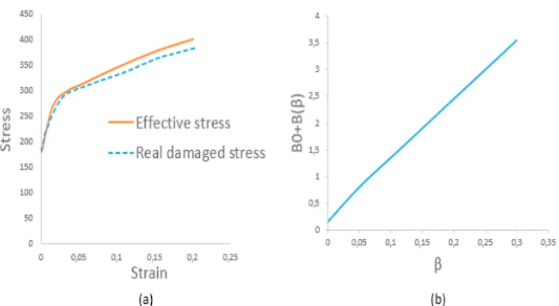
Fig. 2. Input data for Lemaitre model and DC01 (with τ=1): (a) effective stress-strain; (b) damage hardening behaviour.
Fig. 1. (a) Tensile test with a notch of 5 mm; (b) tensile test with a central hole (c) shear test; (d) FE mesh for (a); (e) FE mesh for (b); (f) FE mesh for (d); (g) Formed DC01 sheet by SPIF process (front view with the defined wall angle 𝛼𝛼).
Hereafter, the SPIF geometry studied is a cone of 30mm depth (Fig. 1(g)). The maximum achievable wall angle 𝛼𝛼 can be used as a measure of the formability limit of the SPIF process: a maximum angle of 67° was reached experimentally for DC01 sheets [14].
3. Material model
3.1. Extended Gurson Tvergaard Needleman model
The extended Gurson-Tvergaard-Needleman (GTN) model [5, 6] has been implemented in the in-house finite element code Lagamine, developed by the MSM research team at University of Liège since the 1980s. The Swift isotropic and the Armstrong-Frederick kinematic hardening models are used to describe the hardening behavior of the DC01 steel. The Swift law has the following form:
𝜎𝜎𝑌𝑌(𝜀𝜀𝑒𝑒𝑒𝑒𝑝𝑝 ) = 𝐾𝐾(𝜀𝜀𝑒𝑒𝑒𝑒𝑝𝑝 + 𝜀𝜀0)𝑛𝑛
(1)
where 𝜎𝜎𝑌𝑌 is the flow stress, 𝜀𝜀𝑒𝑒𝑒𝑒𝑝𝑝 is the equivalent plastic strain and K, n,
0 are material constants. The Armstrong-Frederick law only two parameters are present: 𝐶𝐶𝑋𝑋 and 𝑋𝑋sat related to the saturation rate and saturation value of thebackstress 𝑋𝑋𝑖𝑖𝑖𝑖. The classical GTN yield surface is defined by [15]:
𝐹𝐹𝑝𝑝 (𝜎𝜎𝑖𝑖𝑖𝑖, 𝑋𝑋𝑖𝑖𝑖𝑖, 𝑓𝑓, 𝜎𝜎𝑌𝑌) =𝜎𝜎̃𝑒𝑒𝑒𝑒 2 𝜎𝜎𝑌𝑌2 − 1 + 2𝑞𝑞1𝑓𝑓 cosh (− 3 2 𝑞𝑞2𝜎𝜎̃𝑚𝑚 𝜎𝜎𝑌𝑌 ) − (𝑞𝑞1 𝑓𝑓) 2 = 0
(2)
where 𝜎𝜎̃𝑚𝑚 is the macroscopic mean stress, 𝜎𝜎̃𝑒𝑒𝑒𝑒 the macroscopic equivalent effective stress and 𝑓𝑓 is the void volume
fraction (porosity), defined as the average ratio of the void volume to the total volume of the material. The damage parameters 𝑞𝑞1 and 𝑞𝑞2, originally equal to 1.0 in the initial Gurson model, are usually set to 1.5 and 1.0 [6]. The
evolution of voids is additively decomposed in the nucleation 𝑓𝑓𝑛𝑛, growth 𝑓𝑓𝑔𝑔 and shear 𝑓𝑓𝑠𝑠 parts. The growth part
contribution is straightforwardly determined by volume conservation while the nucleation part is defined by: 𝑓𝑓𝑛𝑛̇ = 𝑓𝑓𝑁𝑁 𝑆𝑆𝑁𝑁√2𝜋𝜋exp [− 1 2 ( 𝜀𝜀𝑀𝑀𝑃𝑃− 𝜀𝜀𝑁𝑁 𝑆𝑆𝑁𝑁 ) 2 ] 𝜀𝜀̇𝑀𝑀𝑝𝑝
(3)
4 Ehssen Betaieb / Procedia Manufacturing 00 (2018) 000–000
where 𝜀𝜀𝑀𝑀𝑝𝑝 is the equivalent plastic strain in the matrix and 𝑓𝑓𝑁𝑁, 𝑆𝑆𝑁𝑁, 𝜀𝜀𝑁𝑁 are material parameters. The Nahshon and
Hutchinson shear extension has the following form [16]. 𝑓𝑓̇𝑠𝑠= 𝑘𝑘𝜔𝜔𝑓𝑓𝑓𝑓(𝜎𝜎𝑖𝑖𝑖𝑖)
𝜎𝜎dev𝑖𝑖𝑖𝑖𝜀𝜀̇𝑒𝑒𝑒𝑒𝑝𝑝
𝜎𝜎𝑒𝑒𝑒𝑒
(4)
where 𝑘𝑘𝜔𝜔 is a material parameter, 𝜎𝜎𝑒𝑒𝑒𝑒 the macroscopic equivalent stress, 𝜎𝜎dev𝑖𝑖𝑖𝑖 is deviatoric part of the stress tensor
and 𝑓𝑓(𝜎𝜎𝑖𝑖𝑖𝑖) is a stress scalar function. Finally, coalescence is triggered when the porosity reaches a critical value fcr.
The phenomenon is mathematically represented by an acceleration of the effective void evolution 𝑓𝑓∗ which evolution
is based on the failure porosity 𝑓𝑓F and the critical coalescence porosity 𝑓𝑓𝑐𝑐𝑐𝑐. The latter is a material constant in the
classical GTN model, while the critical porosity is supposed to be reached when the following criterion is no more fulfilled in the Thomason coalescence model [17]:
σ1 σY< [α ( 1 χ − 1) 2 + β √χ] (1 − πχ2)
(5)
where
1 is the maximum principal stress,
is a material parameter defined as a function of the hardening exponentn,
is equal to 1.24 and
is the void space ratio [17]. This extended Gurson model is summarized with more details in [18].3.2. Chaboche and Lemaitre model with 2 damage variables
In order to make the link between the damaged state and the virgin state, the hypothesis of energy conservation has been selected for more physical significance. Zhu [19] proposed an extension of this hypothesis in the case of two damage variables:
𝜎𝜎𝑑𝑑=1 − 𝑑𝑑 𝜎𝜎𝜎𝜎𝑑𝑑 𝑚𝑚= 1 − 𝛿𝛿𝜎𝜎𝑚𝑚
(6)
with σ𝑑𝑑 is the deviatoric stress tensor, σ
𝑚𝑚 is the hydrostatic stress (the bar superscript means effective value) and the
coefficients d and δ are the damage variables.
Fig. 3. Influence of ۃ𝜏𝜏ۄ on the initial damage surface in the stress space.
Fig. 2. Input data for Lemaitre model and DC01 (with τ=1): (a) effective stress-strain; (b) damage hardening behaviour.
100 Ehssen Betaieb / Procedia Manufacturing 00 (2018) 000–000 Ehssen Betaieb et al. / Procedia Manufacturing 29 (2019) 96–104 5 In his model Zhu [19] proposed a modified energy-based damage evolution criterion:
𝐹𝐹𝑑𝑑= −𝑌𝑌𝑑𝑑− ۃ𝜏𝜏ۄ𝑌𝑌𝛿𝛿− 𝐵𝐵0− 𝐵𝐵(𝛽𝛽) = 𝜎𝜎 𝑑𝑑: 𝜎𝜎𝑑𝑑
2𝐺𝐺(1 − 𝑑𝑑)3+
ۃ𝜏𝜏ۄ 𝜎𝜎𝑚𝑚2
𝜒𝜒(1 − 𝛿𝛿)3− 𝐵𝐵0− 𝐵𝐵(𝛽𝛽)
(7)
where 𝑌𝑌𝑑𝑑 and 𝑌𝑌𝛿𝛿 are the damage energy release rates, 𝐺𝐺 and χ are the shear and bulk moduli respectively, 𝐵𝐵0 is the
initial damage strengthening, 𝐵𝐵 the damage strengthening, 𝛽𝛽 the overall damage (𝛽𝛽̇ = 𝑑𝑑̇), ۃ𝜏𝜏ۄ the tensile effect coefficient and it is defined such that the model generates no damage growth in a compression state (Fig. 2) [19]:
ۃ𝜏𝜏ۄ = { 𝛿𝛿⁄ 𝑓𝑓𝑓𝑓𝑓𝑓 𝜎𝜎𝑑𝑑 𝑚𝑚 > 0 0 𝑓𝑓𝑓𝑓𝑓𝑓 𝜎𝜎𝑚𝑚 ≤ 0
(8)
4. Material set of parameters and model validation
The material parameters for DC01 are identified through the comparison between the experimental and numerical results, under different triaxialities, using inverse modelling.
Table 1: DC01 materials parameters for the GTN model
Elastic parameters Swift+Armstrong and Fredrick
E (MPa) 𝜈𝜈 K (MPa) 𝜀𝜀0 𝑛𝑛 𝐶𝐶𝑥𝑥 𝑋𝑋𝑠𝑠𝑠𝑠𝑠𝑠 (MPa)
210000 0.3 542.49 0.0178 0.4328 113.63 81.96
Hill’48 coefficients Damage parameters
F G H N L M 𝑞𝑞1 𝑞𝑞2
0.8103 0.9927 1.4660 2.9246 2.9246 2.9246 1.5 1.0
Nucleation Coalescence Shear (Nahshon and Hutchinson) and
correction parameters
𝑓𝑓0 𝑓𝑓𝑁𝑁 𝑆𝑆𝑁𝑁 𝜀𝜀𝑁𝑁 𝑓𝑓𝑐𝑐𝑐𝑐 𝑓𝑓𝐹𝐹 𝑘𝑘𝜔𝜔 𝑇𝑇1 𝑇𝑇2
0.0008 0.0025 0.175 0.42 0.0055 0.135 0.25 0.35 0.7
The parameter 𝑓𝑓0 is the initial porosity and 𝑘𝑘𝜔𝜔, 𝑇𝑇1, and 𝑇𝑇2 are the material constants used in shear extension model,
more details can be found in [8]. Either the coalescence of void is triggered by the critical porosity 𝑓𝑓𝑐𝑐𝑐𝑐 or defined by
Thomason criterion (5).
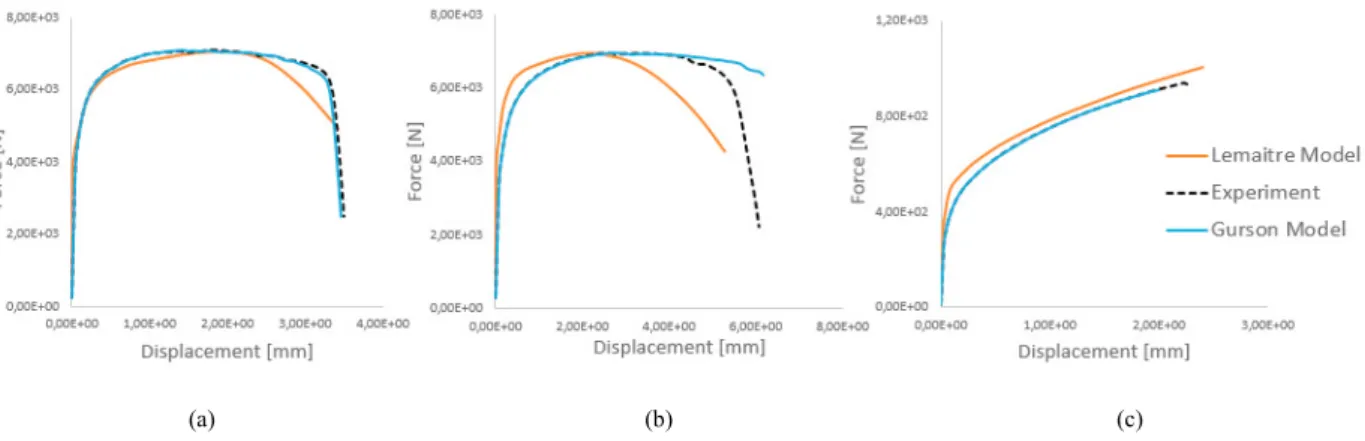
The simulated force-displacement curves for different triaxialities are close to the experimental results when the parameters 𝑘𝑘𝜔𝜔 = 0.25 and 𝑓𝑓𝑐𝑐𝑐𝑐= 0.0055 are used (Fig. 4).
(a) (b) (c)
Fig. 4. Comparison between numerical results and experimental results: (a) tensile test with a notch of 5 mm; (b) tensile test with a central hole; (c) the shear test.
6 Ehssen Betaieb / Procedia Manufacturing 00 (2018) 000–000
These sets of GTN parameters result from a deep investigation with different staggered approaches [18], while the research dedicated to Lemaitre and Chaboche model is at a preliminary state. For the sake of simplicity, von Mises yield locus and isotropic hardening and ۃ𝜏𝜏ۄ value of 1 were chosen for the Lemaitre and Chaboche model. The effective stress-strain curve as well as curve defining damage evolution are defined in Fig. 3.
5. Application of SPIF FE simulation models
In the experimental process, the maximum wall angle 𝛼𝛼 reached without generating failure is 67°. In SPIF simulations, a 8-node solid-shell element, called RESS was used [20]. This element uses the enhanced assumed strain method with one additional deformation mode. Three integration points across the thickness were defined in the present study.
5.1. Extended Gurson Tvergaard Needleman model
By coupling different extensions of Gurson model, the SPIF FE simulations were performed with different variants: GTN: classical GTN model where the coalescence is triggered by the material parameter 𝑓𝑓𝑐𝑐𝑐𝑐.
GTN+Thomason: classical GTN model with the critical coalescence porosity determined by the Thomason criterion.
GTN+Shear: classical GTN model coupled with Nahshon and Hutchinson shear extension.
GTN+Shear+Thomason: combination of GTN model with shear extension and Thomason criterion.
The results summarized in Table 2 and Fig. 5 show that all the variants with different extensions underestimate the experimental maximum wall angle. For the GTN variant, the maximum wall angle without failure is 47°, which is smaller than the experimental one. When coupling with the Thomason criterion, the numerical results are improved up to 51°. However, the influence of Nahshon and Hutchinson shear extension seems to be limited.
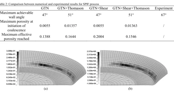
Table 2: Comparison between numerical and experimental results for SPIF process
GTN GTN+Thomason GTN+Shear GTN+Shear+Thomason Experiment
Maximum achievable wall angle 47° 51° 47° 51° 67° Maximum porosity at initiation of coalescence 0.0055 0.01357 0.0055 0.01363 / Maximum effective porosity reached 0.1388 0.1644 0.2004 0.1546 /
Fig. 5. Numerical results of SPIF simulation for the wall angle of 52° with the variant GTN+Shear+ Thomason: (a) the distribution of effective porosity at the end of the simulation; (b) the difference between left hand side and right hand side of Thomason criterion (5), coalescences of void occurs when positive.
In his model Zhu [19] proposed a modified energy-based damage evolution criterion: 𝐹𝐹𝑑𝑑= −𝑌𝑌𝑑𝑑− ۃ𝜏𝜏ۄ𝑌𝑌𝛿𝛿− 𝐵𝐵0− 𝐵𝐵(𝛽𝛽) = 𝜎𝜎 𝑑𝑑: 𝜎𝜎𝑑𝑑 2𝐺𝐺(1 − 𝑑𝑑)3+ ۃ𝜏𝜏ۄ 𝜎𝜎𝑚𝑚2 𝜒𝜒(1 − 𝛿𝛿)3− 𝐵𝐵0− 𝐵𝐵(𝛽𝛽)
(7)
where 𝑌𝑌𝑑𝑑 and 𝑌𝑌𝛿𝛿 are the damage energy release rates, 𝐺𝐺 and χ are the shear and bulk moduli respectively, 𝐵𝐵0 is the
initial damage strengthening, 𝐵𝐵 the damage strengthening, 𝛽𝛽 the overall damage (𝛽𝛽̇ = 𝑑𝑑̇), ۃ𝜏𝜏ۄ the tensile effect coefficient and it is defined such that the model generates no damage growth in a compression state (Fig. 2) [19]:
ۃ𝜏𝜏ۄ = { 𝛿𝛿⁄ 𝑓𝑓𝑓𝑓𝑓𝑓 𝜎𝜎𝑑𝑑 𝑚𝑚 > 0 0 𝑓𝑓𝑓𝑓𝑓𝑓 𝜎𝜎𝑚𝑚 ≤ 0
(8)
4. Material set of parameters and model validation
The material parameters for DC01 are identified through the comparison between the experimental and numerical results, under different triaxialities, using inverse modelling.
Table 1: DC01 materials parameters for the GTN model
Elastic parameters Swift+Armstrong and Fredrick
E (MPa) 𝜈𝜈 K (MPa) 𝜀𝜀0 𝑛𝑛 𝐶𝐶𝑥𝑥 𝑋𝑋𝑠𝑠𝑠𝑠𝑠𝑠 (MPa)
210000 0.3 542.49 0.0178 0.4328 113.63 81.96
Hill’48 coefficients Damage parameters
F G H N L M 𝑞𝑞1 𝑞𝑞2
0.8103 0.9927 1.4660 2.9246 2.9246 2.9246 1.5 1.0
Nucleation Coalescence Shear (Nahshon and Hutchinson) and
correction parameters
𝑓𝑓0 𝑓𝑓𝑁𝑁 𝑆𝑆𝑁𝑁 𝜀𝜀𝑁𝑁 𝑓𝑓𝑐𝑐𝑐𝑐 𝑓𝑓𝐹𝐹 𝑘𝑘𝜔𝜔 𝑇𝑇1 𝑇𝑇2
0.0008 0.0025 0.175 0.42 0.0055 0.135 0.25 0.35 0.7
The parameter 𝑓𝑓0 is the initial porosity and 𝑘𝑘𝜔𝜔, 𝑇𝑇1, and 𝑇𝑇2 are the material constants used in shear extension model,
more details can be found in [8]. Either the coalescence of void is triggered by the critical porosity 𝑓𝑓𝑐𝑐𝑐𝑐 or defined by
Thomason criterion (5).
The simulated force-displacement curves for different triaxialities are close to the experimental results when the parameters 𝑘𝑘𝜔𝜔= 0.25 and 𝑓𝑓𝑐𝑐𝑐𝑐= 0.0055 are used (Fig. 4).
(a) (b) (c)
Fig. 4. Comparison between numerical results and experimental results: (a) tensile test with a notch of 5 mm; (b) tensile test with a central hole; (c) the shear test.
These sets of GTN parameters result from a deep investigation with different staggered approaches [18], while the research dedicated to Lemaitre and Chaboche model is at a preliminary state. For the sake of simplicity, von Mises yield locus and isotropic hardening and ۃ𝜏𝜏ۄ value of 1 were chosen for the Lemaitre and Chaboche model. The effective stress-strain curve as well as curve defining damage evolution are defined in Fig. 3.
5. Application of SPIF FE simulation models
In the experimental process, the maximum wall angle 𝛼𝛼 reached without generating failure is 67°. In SPIF simulations, a 8-node solid-shell element, called RESS was used [20]. This element uses the enhanced assumed strain method with one additional deformation mode. Three integration points across the thickness were defined in the present study.
5.1. Extended Gurson Tvergaard Needleman model
By coupling different extensions of Gurson model, the SPIF FE simulations were performed with different variants: GTN: classical GTN model where the coalescence is triggered by the material parameter 𝑓𝑓𝑐𝑐𝑐𝑐.
GTN+Thomason: classical GTN model with the critical coalescence porosity determined by the Thomason criterion.
GTN+Shear: classical GTN model coupled with Nahshon and Hutchinson shear extension.
GTN+Shear+Thomason: combination of GTN model with shear extension and Thomason criterion.
The results summarized in Table 2 and Fig. 5 show that all the variants with different extensions underestimate the experimental maximum wall angle. For the GTN variant, the maximum wall angle without failure is 47°, which is smaller than the experimental one. When coupling with the Thomason criterion, the numerical results are improved up to 51°. However, the influence of Nahshon and Hutchinson shear extension seems to be limited.
Table 2: Comparison between numerical and experimental results for SPIF process
GTN GTN+Thomason GTN+Shear GTN+Shear+Thomason Experiment
Maximum achievable wall angle 47° 51° 47° 51° 67° Maximum porosity at initiation of coalescence 0.0055 0.01357 0.0055 0.01363 / Maximum effective porosity reached 0.1388 0.1644 0.2004 0.1546 /
Fig. 5. Numerical results of SPIF simulation for the wall angle of 52° with the variant GTN+Shear+ Thomason: (a) the distribution of effective porosity at the end of the simulation; (b) the difference between left hand side and right hand side of Thomason criterion (5), coalescences of void occurs when positive.
102 Ehssen Betaieb / Procedia Manufacturing 00 (2018) 000–000 Ehssen Betaieb et al. / Procedia Manufacturing 29 (2019) 96–104 7 In Fig. 5, an example of the numerical results for 52° (minimum wall angle leading to failure) of wall angle is illustrated when the GTN+Shear+Thomason variant is used. Fig. 5 (a) presents the distribution of the effective porosity 𝑓𝑓∗ at end of the simulation. It is clearly that the 𝑓𝑓∗ has already surpassed 𝑓𝑓
𝐹𝐹 which is the indicator of the failure of the
material. For the same moment, the difference between left hand side and right hand side of Thomason criterion (5) is illustrated in Fig. 5 (b). The coalescence occurs when the latter is positive. In addition, it shows a similar distribution field as the effective porosity.
5.2. Chaboche and Lemaitre model
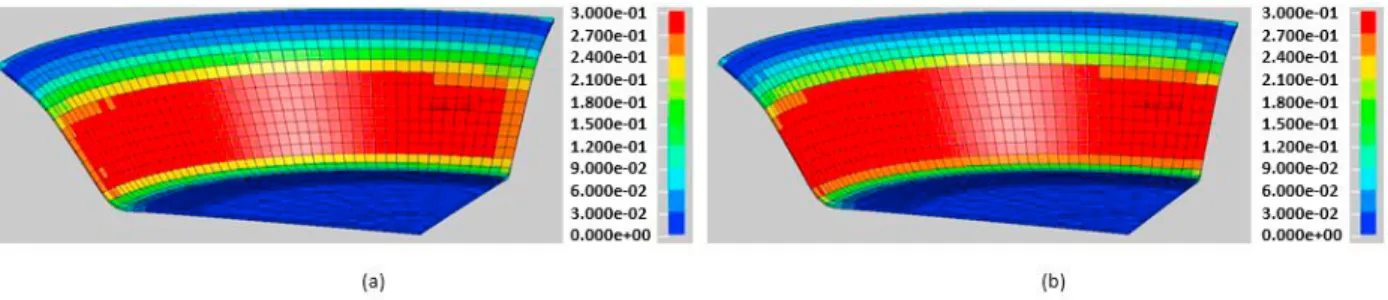
In Fig. 6, we present the distribution of damage at the end of the simulation for Lemaitre and Chaboche model. For the wall angle of 55° (Fig. 6 (a)), the maximum value of damage (𝑑𝑑𝑚𝑚𝑚𝑚𝑚𝑚= 0.29) does not reach the critical value while
for the wall angle of 57° (Fig. 6 (b)), the value of damage (𝑑𝑑𝑚𝑚𝑚𝑚𝑚𝑚= 0.39) surpassed the critical value. As a conclusion,
the critical wall angle using the currently identified parameters is 57° whereas the experimental failure angle is 67°. This error could be partially caused by the material parameter identification procedure.
Fig. 6. Numerical results of SPIF simulations with Lemaitre model: damage value (a) for the wall angle of 55°; (b) for the wall angle of 57°. 6. Conclusions
Two models, namely an extended Gurson model and a Lemaitre and Chaboche model, are applied to study the SPIF process in a truncated cone geometry. The Gurson model shows a good capability to predict the mechanical behavior and to capture the failure of the material under different triaxialities within in-plane mechanical tests. However, when the same set of parameters is used in SPIF simulations, it underestimates the maximum achievable wall angle. Coupling classical GTN model with Thomason coalescence criterion only slightly improves the simulated maximum wall angle. Limited influence of Nahshon and Hutchinson shear extension of GTN model can be noticed in the SPIF simulation.
A potential explanation for the poor accuracy of the GTN model in failure prediction during SPIF (47° or 51° compared to 67°, see Table 2) would rely on its inability to describe the strain localization and the associated thinning of the metal sheet in the coalescence regime [18]. This could be attributed to the fact that the onset of strain localization is solely driven by the evolution of porosity.
The Chaboche and Lemaitre model permitted to obtain significantly better results in failure prediction (57°), even if the identification of the material parameters was not conducted thoroughly at this stage. For instance, improvement of the results could be expected with the use of an advanced optimization algorithm. Another possible strategy to improve the failure prediction would be to partially include SPIF results in the identification process, e.g. identification of the parameters including one SPIF process and to check the predictive capabilities of the model on another SPIF process. Additionally, the richness of the set of experimental results could be analyzed mathematically with approaches such as the proposed by Ben Hmida [21], in order to obtain accurate material parameters.
8 Ehssen Betaieb / Procedia Manufacturing 00 (2018) 000–000 Acknowledgements
C.F. Guzmán acknowledges the support from the Chilean Department of Education (MINEDUC), grant Proyecto Fortalecimiento Usach USA1799 SE162814. FNRS Research Director A.M. Habraken acknowledges the support from Belgian Fund for Scientific Research (FRS-FNRS) and specifically PDR MatSPIF-ID FRS-FNRS for E. Betaieb PhD grant. Computational resources have been provided by the Consortium des Équipements de Calcul Intensif (CÉCI), funded by the FRS-FNRS under Grant No. 2.5020.11.
References
[1] J. R. Duflou, A.-M. Habraken, J. Cao, R. Malhotra, M. Bambach, D. Adams, H. Vanhove, A. Mohammadi, J. Jeswiet, Single point incremental forming: state-of-the-art and prospects,International Journal of Material Forming., 11 (2017) 743-773.
[2] A. López, G. Centeno, A. Martínez-Donaire, D. Morales-Palma, C. Vallellano, Experimental and numerical analysis of the flanging process by SPIF, Journal of physics: Conference Series, 1063 (2018) 012086.
[3] R. Malhotra, L. Xue, T. Belytschko, J. Cao, Mechanics of fracture in single point incremental forming, Journal of Materials Processing Technology, 212 (2012) 1573–1590.
[4] L. Xue, Constitutive modeling of void shearing effect in ductile fracture of porous materials, Engineering Fracture Mechanics, 75 (2008) 3343–3366.
[5] A. L. Gurson, Continuum Theory of Ductile Rupture by Void Nucleation and Growth: Part I-Yield Criteria and Flow Rules for Porous Ductile Media, Journal of Engineering Materials and Technology, 99 (1977) 2–15.
[6] V. Tvergaard, Material Failure by Void Growth to Coalescence, Advances in Applied Mechanics, 27 (1989) 83-151.
[7] J. Li, S. Li, Z. Xie, W. Wang, Numerical simulation of incremental sheet forming based on GTN damage model, International Journal of Advanced Manufacturing Technology, 81 (2015) 2053-2065.
[8] C. F. Guzmán, S. Yuan, L. Duchêne, E. I. Saavedra Flores, and A. M. Habraken, Damage prediction in single point incremental forming using an extended Gurson model, International Journal of Solids and Structures, 151 (2018) 45-56.
[9] S. Gatea, H. Ou, B. Lu, and G. McCartney, Modelling of ductile fracture in single point incremental forming using a modified GTN model, Engineering Fracture Mechanics, 186 (2017) 59-79.
[10] V. Tvergaard, A. Needleman, Analysis of the cup-cone fracture in a round tensile bar, Acta Metallurgica, 32 (1984) 157-169.
[11] J. Lemaitre, A Continuous Damage Mechanics Model for Ductile Fracture, Journal of Engineering Materials and Technology, 107 (1985) 83–89.
[12] G. Hapsari, R. Ben Hmida, F. Richard, S. Thibaud, P. Malécot, A Procedure for Ductile Damage Parameters Identification by Micro Incremental Sheet Forming, Procedia Engineering, 183 (2017) 125-130.
[13] A. Kumar, A. K. Singh, A. Shrivastva, S. Mishra, K. Narasimhan, Failure prediction in incremental sheet forming based on Lemaitre damage model, Journal of Physics: Conference Series, 1063 (2018) 012152.
[14] J. R. Duflou, B. Callebaut, J. Verbert, H. De Baerdemaeker, Improved SPIF performance through dynamic local heating, International Journal of Machine Tools and Manufacture, 48 (2008) 543-549.
[15] V. Tvergaard, Influence of voids on shear band instabilities under plane strain conditions, International Journal of Fracture, 17 (1981) 389-407.
[16] K. Nahshon, J. W. Hutchinson, Modification of the Gurson Model for shear failure, European Journal of Mechanics - A/Solids, 27 (2008) 1-17.
[17] Z. Zhang, C. Thaulow, J. Ødegård, A complete Gurson model approach for ductile fracture, Engineering Fracture Mechanics, 67 (2000) 155-168.
[18] C. F. Guzmán, Experimental and Numerical Characterization of Damage and Application to Incremental Forming, PhD Thesis, University of Liège, 2016.
http://hdl.handle.net/2268/192884
[19] Y. Zhu, Contribution to the local approach of fracture in solid dynamics., PhD Thesis, University of Liège, 1992. http://bictel.ulg.ac.be/ETD-db/collection/available/ULgetd-03112008-112606/
[20] A. Ben Bettaieb, J. Velosa, D. Sena, R. J. A. De Sousa, R. A. F. Valente, A. M. Habraken, L. Duchêne, On the comparison of two solid-shell formulations based on in-plane reduced and full integration schemes in linear and non-linear applications, Finite Elements in Analysis and Design, 107 (2015) 44-59.
micro-In Fig. 5, an example of the numerical results for 52° (minimum wall angle leading to failure) of wall angle is illustrated when the GTN+Shear+Thomason variant is used. Fig. 5 (a) presents the distribution of the effective porosity 𝑓𝑓∗ at end of the simulation. It is clearly that the 𝑓𝑓∗ has already surpassed 𝑓𝑓
𝐹𝐹 which is the indicator of the failure of the
material. For the same moment, the difference between left hand side and right hand side of Thomason criterion (5) is illustrated in Fig. 5 (b). The coalescence occurs when the latter is positive. In addition, it shows a similar distribution field as the effective porosity.
5.2. Chaboche and Lemaitre model
In Fig. 6, we present the distribution of damage at the end of the simulation for Lemaitre and Chaboche model. For the wall angle of 55° (Fig. 6 (a)), the maximum value of damage (𝑑𝑑𝑚𝑚𝑚𝑚𝑚𝑚 = 0.29) does not reach the critical value while
for the wall angle of 57° (Fig. 6 (b)), the value of damage (𝑑𝑑𝑚𝑚𝑚𝑚𝑚𝑚 = 0.39) surpassed the critical value. As a conclusion,
the critical wall angle using the currently identified parameters is 57° whereas the experimental failure angle is 67°. This error could be partially caused by the material parameter identification procedure.
Fig. 6. Numerical results of SPIF simulations with Lemaitre model: damage value (a) for the wall angle of 55°; (b) for the wall angle of 57°. 6. Conclusions
Two models, namely an extended Gurson model and a Lemaitre and Chaboche model, are applied to study the SPIF process in a truncated cone geometry. The Gurson model shows a good capability to predict the mechanical behavior and to capture the failure of the material under different triaxialities within in-plane mechanical tests. However, when the same set of parameters is used in SPIF simulations, it underestimates the maximum achievable wall angle. Coupling classical GTN model with Thomason coalescence criterion only slightly improves the simulated maximum wall angle. Limited influence of Nahshon and Hutchinson shear extension of GTN model can be noticed in the SPIF simulation.
A potential explanation for the poor accuracy of the GTN model in failure prediction during SPIF (47° or 51° compared to 67°, see Table 2) would rely on its inability to describe the strain localization and the associated thinning of the metal sheet in the coalescence regime [18]. This could be attributed to the fact that the onset of strain localization is solely driven by the evolution of porosity.
The Chaboche and Lemaitre model permitted to obtain significantly better results in failure prediction (57°), even if the identification of the material parameters was not conducted thoroughly at this stage. For instance, improvement of the results could be expected with the use of an advanced optimization algorithm. Another possible strategy to improve the failure prediction would be to partially include SPIF results in the identification process, e.g. identification of the parameters including one SPIF process and to check the predictive capabilities of the model on another SPIF process. Additionally, the richness of the set of experimental results could be analyzed mathematically with approaches such as the proposed by Ben Hmida [21], in order to obtain accurate material parameters.
Acknowledgements
C.F. Guzmán acknowledges the support from the Chilean Department of Education (MINEDUC), grant Proyecto Fortalecimiento Usach USA1799 SE162814. FNRS Research Director A.M. Habraken acknowledges the support from Belgian Fund for Scientific Research (FRS-FNRS) and specifically PDR MatSPIF-ID FRS-FNRS for E. Betaieb PhD grant. Computational resources have been provided by the Consortium des Équipements de Calcul Intensif (CÉCI), funded by the FRS-FNRS under Grant No. 2.5020.11.
References
[1] J. R. Duflou, A.-M. Habraken, J. Cao, R. Malhotra, M. Bambach, D. Adams, H. Vanhove, A. Mohammadi, J. Jeswiet, Single point incremental forming: state-of-the-art and prospects,International Journal of Material Forming., 11 (2017) 743-773.
[2] A. López, G. Centeno, A. Martínez-Donaire, D. Morales-Palma, C. Vallellano, Experimental and numerical analysis of the flanging process by SPIF, Journal of physics: Conference Series, 1063 (2018) 012086.
[3] R. Malhotra, L. Xue, T. Belytschko, J. Cao, Mechanics of fracture in single point incremental forming, Journal of Materials Processing Technology, 212 (2012) 1573–1590.
[4] L. Xue, Constitutive modeling of void shearing effect in ductile fracture of porous materials, Engineering Fracture Mechanics, 75 (2008) 3343–3366.
[5] A. L. Gurson, Continuum Theory of Ductile Rupture by Void Nucleation and Growth: Part I-Yield Criteria and Flow Rules for Porous Ductile Media, Journal of Engineering Materials and Technology, 99 (1977) 2–15.
[6] V. Tvergaard, Material Failure by Void Growth to Coalescence, Advances in Applied Mechanics, 27 (1989) 83-151.
[7] J. Li, S. Li, Z. Xie, W. Wang, Numerical simulation of incremental sheet forming based on GTN damage model, International Journal of Advanced Manufacturing Technology, 81 (2015) 2053-2065.
[8] C. F. Guzmán, S. Yuan, L. Duchêne, E. I. Saavedra Flores, and A. M. Habraken, Damage prediction in single point incremental forming using an extended Gurson model, International Journal of Solids and Structures, 151 (2018) 45-56.
[9] S. Gatea, H. Ou, B. Lu, and G. McCartney, Modelling of ductile fracture in single point incremental forming using a modified GTN model, Engineering Fracture Mechanics, 186 (2017) 59-79.
[10] V. Tvergaard, A. Needleman, Analysis of the cup-cone fracture in a round tensile bar, Acta Metallurgica, 32 (1984) 157-169.
[11] J. Lemaitre, A Continuous Damage Mechanics Model for Ductile Fracture, Journal of Engineering Materials and Technology, 107 (1985) 83–89.
[12] G. Hapsari, R. Ben Hmida, F. Richard, S. Thibaud, P. Malécot, A Procedure for Ductile Damage Parameters Identification by Micro Incremental Sheet Forming, Procedia Engineering, 183 (2017) 125-130.
[13] A. Kumar, A. K. Singh, A. Shrivastva, S. Mishra, K. Narasimhan, Failure prediction in incremental sheet forming based on Lemaitre damage model, Journal of Physics: Conference Series, 1063 (2018) 012152.
[14] J. R. Duflou, B. Callebaut, J. Verbert, H. De Baerdemaeker, Improved SPIF performance through dynamic local heating, International Journal of Machine Tools and Manufacture, 48 (2008) 543-549.
[15] V. Tvergaard, Influence of voids on shear band instabilities under plane strain conditions, International Journal of Fracture, 17 (1981) 389-407.
[16] K. Nahshon, J. W. Hutchinson, Modification of the Gurson Model for shear failure, European Journal of Mechanics - A/Solids, 27 (2008) 1-17.
[17] Z. Zhang, C. Thaulow, J. Ødegård, A complete Gurson model approach for ductile fracture, Engineering Fracture Mechanics, 67 (2000) 155-168.
[18] C. F. Guzmán, Experimental and Numerical Characterization of Damage and Application to Incremental Forming, PhD Thesis, University of Liège, 2016.
http://hdl.handle.net/2268/192884
[19] Y. Zhu, Contribution to the local approach of fracture in solid dynamics., PhD Thesis, University of Liège, 1992. http://bictel.ulg.ac.be/ETD-db/collection/available/ULgetd-03112008-112606/
[20] A. Ben Bettaieb, J. Velosa, D. Sena, R. J. A. De Sousa, R. A. F. Valente, A. M. Habraken, L. Duchêne, On the comparison of two solid-shell formulations based on in-plane reduced and full integration schemes in linear and non-linear applications, Finite Elements in Analysis and Design, 107 (2015) 44-59.
micro-104 Ehssen Betaieb / Procedia Manufacturing 00 (2018) 000–000 Ehssen Betaieb et al. / Procedia Manufacturing 29 (2019) 96–104 9 formage incrémental, PhD Thesis, Supervision: S. Thibaud, University of Franche-Comté, 2014.