Université de Montréal
The Co-Design Methodologies
On Click Router Application System
Présenté par:
Dan Li
Département d’informatique et de recherche opérationnel le
Faculté des arts et des sciences
Mémoire présenté à la Faculté des études supérieures
en vue de l’obtention du grade de
Maître en Informatique
Décembre, 2004
2Q5
-\I i_: ‘JUniversité
de Montréal
Direction des bibliothèques
AVIS
L’auteur a autorisé l’Université de Montréal à reproduire et diffuser, en totalité ou en partie, par quelque moyen que ce soit et sur quelque support que ce soit, et exclusivement à des fins non lucratives d’enseignement et de recherche, des copies de ce mémoire ou de cette thèse.
L’auteur et les coauteurs le cas échéant conservent la propriété du droit d’auteur et des droits moraux qui protègent ce document. Ni la thèse ou le mémoire, ni des extraits substantiels de ce document, ne doivent être imprimés ou autrement reproduits sans l’autorisation de l’auteur.
Afin de se conformer à la Loi canadienne sur la protection des renseignements personnels, quelques formulaires secondaires, coordonnées ou signatures intégrées au texte ont pu être enlevés de ce document. Bien que cela ait pu affecter la pagination, il n’y a aucun contenu manquant. NOTICE
The author of this thesis or dissertation has granted a nonexclusive license allowing Université de Montréal to reproduce and publish the document, in part or in whole, and in any format, solely for noncommercial educational and research purposes.
The author and co-authors if applicable retain copyright ownership and moral rights in this document. Neither the whole thesis or dissertation, nor substantial extracts from it, may be printed or otherwise reproduced without the author’s permission.
In compliance with the Canadian Privacy Act some supporting forms, contact information or signatures may have been removed from the document. While this may affect the document page count, it does not represent any Ioss of content from the document.
Ce mémoire intitulé
The Co-Design Methodologies
on Click Router Application System
Présenté par:
Dan Li
a éte évalué par un jury composé des personnes suivantes:
Jean Pierre David
Président-rapporteur
El Mostapha Aboulharnid
Directeur de recherche
Gabriela Nicolescu
Co-directeur
Claude Frasson
Membre du jury
Résumé
Afin d’obtenir des meilleurs performances pour les applications actuels de plus en plus complexes, aujourd’hui le domaine de co-conception logiciel/matériel a pris une grande ampleur. En même temps, plusieurs architectures multiprocesseurs efficaces ont été proposées récemment et elles sont devenue la solution la plus populaire dans le domaine des systèmes embarques logiciels/matériels.
Des méthodologies innovateurs de conception sont nécessaires actuellement pour respecter les contraintes fortes de coût, performance et temps de mise sur le marché. Un des points clé de ces méthodologies et un des défies actuelles des concepteurs est donné par l’étape de partitiomiernent logiciel/rnatériel en partant d’une spécification de haut niveau pour l’application à implanter.
Dans ce contexte, les contributions de notre travail de recherche sont
(1) La proposition d’une méthodologie de partitionnernent logiciel/matériel. Nous avons utilisé comme application le routeur IPV4 Click fourni par l’Université Berkeley et nous avons analyse l’impact de la méthodologie sur les performances de ce système.
(2) Le développement et l’évaluation d’une architecture multiprocesseur intégrant 3 processeurs, dans le cas du routeur IPV4 à l’aide de l’outil StepNP de la compagnie STMicroelectronics. Cette approche peut être utilisée pour la conception de nouvelles architectures, intégrant plus de 3 processeurs.
Notre évaluation montre un gain en performances dans le cas des architectures logicielles/matériels (notre systeme a été deux fois plus rapide quand une partie de fonctions logiciels ont été implantées en matériel). L’architecture multiprocesseur présente une vitesse de traitement des paquets deux fois plus grande qu’une architecture monoprocesseur.
Keyword Conception logiciel/matériel, partitionnement, systèmes multiprocesseur, routeur Click, StepNP, SystemC
Abstract
To improve the overail performance of the current increasingly complex applications, the combination of hardware and software solutions must be valued in co-design area. In addition, multiple processors architectures lias been introduced as a generic model to design many specific application and they becarne the most efficient and popular solution in the field of hardware/software systems.
In order to respect the straiglit constraints of cost, performances and time-to-market imposed for multiprocessor embedded systems designers, a mew generation of methodologies is required. One of the key points and current important challenge in such methodologies is to perforrn hardware/software partitioning starting from a high level specification of the application to be irnplemented.
In this context, the contributions ofour work are:
(1) Proposing a rnethodology for hardware/software partitioning. We use the Click IPv4 software router (provided by Berkelcy University) as an application and analyze the methodology impact
onthe packets processing performance of Click IPv4 router.
(2) Developing and evaluating an architecture implementing Click IPV4 software router on three ARM CPUs with the help of StepNP platform provided by STMcirolectronics Company. This approach may be extended to implementing Click software on more than three multi-processors. As a result, the speedup of IPv4 Click router application system almost doubles in the help of combination of hardware/software co-design comparing with using only software implementation on Click router. In multiprocessors architecture for Click router integrating tbree processors, the overall speed to process a packet is about 1.84 faster than that of the Click router single processor architecture.
Keyword : Hardware/Software co-design, Partitioning, Multiprocessors, Click router, StepNP, SystemC
111
Table of Contents
Résumé .
Abstract ii
Table of Contents iii
List of figures vi
List of Tables vii
Acknowledgement ix
CHAPTER 1 Introduction 1
1 .1 Context and motivations I
1.2 Objective 2
1.3 Contribution 2
1.4 Thesis structure 2
CHAPTER 2 Hardware /Software Co-Design 3
2.1 Definition & Motivation for hardware/software co-design 3
2.2 The hardware/software co-Design flow 4
2.3 Target architectures 6
2.4 Partitioning: definition and problems 7
2.4.1 Recent problems on hardware/software co-design 7
2.4.2 Partitioning concems 10
2.4.3 The strategies ofpartitioning 13
2.5 Our work on the hardware/software co-design 14
2.6 Our partitioning methodology 15
CHAPTER 3 Multiprocessor Concepts 16
3.1 The basic knowledge on multiprocessors 16
3.3 Our work on the multiprocessor . 27 3.4 Our methodology for Click implementation on the multiprocessor 29
CHAPTER 4 Hardware/Software Co-Design Methodology on Partitioning 30
4.1 The general presentation for rnethodology 31
4.2 StepNP platform introduction 33
4.3 Click router 35
4.3.1 Click router element connection 35
4.3.2 Click router features 36
4.3.3 Click router general forwarding principle 37
4.3.4 Click configuration for IPv4 router 37
4.4 Partitioning methodology 40
4.4.1 Partitioning implementation considerations 40
4.4.2 Partitioning- simulation considerations 42
4.5 Algorithm analysis 44
CHAPTER 5 The Methodology to Imptement Click Router on Multiprocessor 51
5.1 General presentation ofthe rnethodology 51
5.1.1 The architecture description 51
5.1.2 The benefit ofthe rnethodology 54
5.2 Mapping the program on three processors 55
5.3 Exchanging data between three processors 5$
5.3.1 Hardware architecture building 5$
5.3.2 Software
(
Element) 625.4 The overail description ofthe communication between processors 66
CHAPTER 6 Performance Evaluatïon 69
6.1 Evaluation ofthe hardware/software co-design methodology in Chapter 4 69
6.1.1 Synthesis tools 69
6.1.2 hiitial constraints for synthesis 69
6.1.3 Synthesis result 70
V
6.1.5 Software/hardware analysis .71
6.1.6 Cick Wv4 router performancd in co-design 72
6.2 Evaluation ofthe methodology explained in Chapter5 74
6.2.1 Experimental tools and approach 74
6.2.2 Experimental resuit 75
6.2.3 The discussion ofresuits 77
CHAPTER 7 Conclusion and Future Work $0
REFERENCE 81
Appendix A CSDECIPTTL- FM State Graph Style for Process $5 Appendix B CSFRAGMENT - FM State GRAPH Style for Process 86
Appendix C CSSTRTP - FM State Graph Style for Process 88
Appendix D CSCHECSDM - fM State Graph Style for Process 89
Appendix E CSDECIPTTL - Schedule Surnrnary 91
Appendix f CSFRAGMGENTER- Schedule Surnmary 92
Appendix G CSLOOKUP ROUTEG TABLE - Schedule Sumrnary 93
Appendix H CSSTRIP- Schedule Surnrnary 94
Appendix I CSIPFRAGMENTER-SysternC Code 95
List of Figures
Figure 2-1 Hardware/software co-design frarnework 5
Figure 2-2 a single-processor architecture 6
Figure 2-3 a typical multiprocessor architecture 6
figure 2-4 Hardware/software mapping 11
Figure2-5 Hardware sharing 11
Figure 2-6 Functional scheduling 12
Figure 2-7 Interfacing 13
Figure 3-1 A distributed system on embedded chip 17
Figure 3-2 A single-bus multiprocessor 1 8
Figure 3-3 multiprocessor architecture with Network connection 19 Figure 3-4 An example to describe ihe influence ofprocess partitioning
on distributed system performance 22
Figure3-5 how process allocation affects the performance
ofdistributed computing system 23
Figure 3-6 Generic architecture model 25
Figure 3-7 the generic design methodoÏogy of
a multiprocessor SoC architecture 26
Figure 4-1 the general framework ofthe approach
on how to map software onto hardware 32
Figure 4-2 SimplePacket platform in StepNP 34
Figure 4-3 Click Configuration for Ipv4 Router 38
Figure 4-4 The crucial path in Click Pv4 router 41
Figure 4-5 Hard/software Co-design for Click router on SimplePacket Platform 42
Figure 4-6 The code description ofDecIPTTL element 45
Figure 4-7 The code description of IPFragmenter Element 46
vii
Figure 4-9 The code description oflookupiPRouter Element .48 figure 4-10 Tue methodology about longest matching prefix in routing table 49
Figure 5-1 the general description on how Click works on three ARMprocessors 52 Figure 5-2 Click router code modification for multiprocessor 56
Figure 5-3-1 ARM Processor modification in StepNP 57
figure 5-3-2 the instance of Click on three ARM7 Processors architecture 58 Figure 5-4 Hardware architecture with shared lock structure on stepNP 59 Figure 5-5-l The internal operations of anARIVI processor 60 Figure 5-5-2 The internai operations ofan ARM processor 61 Figure 5-6 the segment code to write packets into
the shared hardware on StepNP platform 63
Figure 5-7 the segment code to read packets from
the shared hardware on StepNP platforrn 64
Figure 5-8 IPv4 original file and IPv4 configuration drawing with two new elernents 65 f igure 5-9 The communication between three processors
with the help of software & hardware 66
figure 6-i The code segment in IPFragment element 72
List of Tables
Table 4-1 the click element computational cycles from simulation 43
Table 6-1 Result from CoCentric SystemC Complier 70
Table 6-2 Cycle Number in Strip module execution 71
Table 6-3 Cycle Number in DecIPTTL module execution 71
Table 6-4 Cycle Number in lPFragmenter module execution 71 Table 6-5 Cycle Numberin Lookup Routing Table module execution 72 Table 6-6 Irnproved status for each elernent in IPv4 Click router 73 Table 6-7 The cycles counted for packets passing the
Click router on two architectures respectively 76 Table 6-8 The comparison ofthe packet processing performances
ix
Acknowledgement
This thesis work has been a challenge in my whole study period. Throughout this period, I received much support and help from the professors and friends.
Firstly, I would like to appreciate Prof. E! Mostapha Aboulharnid, my director, for his continued guidance, bis encouragement, his care and his support through the whole course of this thesis work. Hc bas constantly given much precious advice on the thesis work by bringing up relevant accomplishment in this research area. I also owe rny gratitude to Prof Gabriela Nicolescu, my co-director, for her continued support, ber encouragement, her thoughtful advice and her meticulous work for this thesis work.
Great appreciation is also given to David Quinn, and Mortimer Hubin, who have given me generous belp on this tbesis work. Based on their work on the hardware/software co-design of Click router application system, I can continue to complete this thesis work. Especially I received a lot ofbenefit from the discussion with David Quinn, who gave bis precious time and invaluable effort for this thesis work.
Many thanks to ail of my friends Qin Lisheng and Zhang Hong for their encouragement, and their valuable comments on my thesis report.
finaily, I would like to give a special acknowledgernent to my sister, Li Wei, for her consistently patience, faith on me. T also would like to give such acknowledgement to my parents for their understanding, and making all ofthis corne true.
Introductïon
1.1 Context ami motivations
Due to the popularity of the Internet, the traffic on the Internet increases rapidly for the last ten to fifteen years. The performance of router, a core part of network, is considered to be an important factor to affect the overali performance of the whole network. TypicaÏly, a router accepts data-grams and relays them on toward their destination and is responsible for deterrnining the route[13].
Ever-increasing requirements from network applications, however, drive routers to supply more new network services such as packet tagging, application-level proxies, applications-specific packet dropping, performance monitoring, intrusion detections, and various filter and firewails rapidly{4]. While rnost backbone routers improve their forwarding process of packets using appïications specific integrated circuits (ASIC’s), software based edged routers[2][5] hecome attractive due to high-performance network processors.
Thus, modular components routers architecture take advantage over that of conventional routers on flexibility and extension. Such a typical system is MITs Click router[ 1] which is a modular architecture built from different software modular components(elements). Component-based routers make software networking easier to program.
However, component tecimiques, which spiit a complicated, big computation task into some small, simple computation units(components) and build the linkage to pass the messages(changes) between component possessing reuse and flexibility, suffer inefficiencies that monolithic software can avoid [1lJ. One way to avoid modularity overhead is to consider applying hardware/software co-design methodology to increase the computation in a component and to offset the cost of the communications among components. This methodology is implemented on StepNP[6j platform that we use in our work
2
1.2 Objective
In the presented context, the main objectives of our work are:
1) Bring a new solution for the application partitioning onto hardware/software architecture using high-level simulation in co-design.
2) Exploring how to implement the Click router application system (see Chapter 4.3) on multiprocessors and evaluating the performance of such an architecture.
1.3 Contribution
In order to reach our objective the proposed contributions are:
1) Proposing a rnethodology for applications partitioning. We use the Click Pv4 software router as an application and analyze the methodology impact on the packets processing performance of Click IPv4 router.
2) Developing an exccutahle application-specific architecture (secChapter S1.1) ofimplernenting
Click software router on three ARM CPUs with the help of StepNP platforrn and giving the
evaluation ofthe method. This approacli may be extended to implementing Click softwareon more
than three multi-processors.
1.4 Thesis structure
In the next chapters of the thesis, we introduce basic knowledge of HW/SW codesign in Chapter 2 and multiprocessors in Chapter 3. Then, we present a co-design methodology on how to partition Click router into software parts and hardware parts, and on how to implernent those parts
respectively on StepNP platform
(
Chapter 4), and a methodology implementing Click on three processors in Chapter 5. Chapter 6 will discuss the evaluation of those two methodologies by simulation means. In the final section, we will discuss future work as well.3
Chapter 2
HardwarelSoftware Co-Design
2.1 Definition & motivation for hardware/software co-design
Hardware/software co-design refers to the collaborative design of hardware and software. considering the hardware and software conculTently to design computing systems that meet ail performance requirernents and minimize the arnount of hardware resources[14]. Two main considerations stimulate the need for hardware/software co-design in digital systems design.
From the hardware aspect, the fact that dedicated computing systems need to react external input instantly and to deal with more complicated computation of digital systems raises higher demands on Ihe performance to today’s digital systems. With the help of ASÏCs processing data in parallel with processors. hardware solution may shorten execution rime. improving the overail performance of digital systems. However. ASICs often are flot high-volurne produced. They are ofien designed to meet the performance need for the application systems. Thus, hardware solution may be more expensive than software solution [15] due to the development cost ofASICs.
From the software aspect, software is likely reused on variotis processors and modified more easily. Such possibility may reduce design efforts and shorten time-to-market. Therefore, while considering cost constraints, designers may values the re-programmabiÏity and flexibility of software solutions. However, software ofien performs tasks in serial order and may flot complete some operations while respecting time constrains[15].
In summary. both software and hardware components are interesting for complex systems implementations. Currently, all systems include both types of components, and the design of these types of systems requires new methodologies to reduce the design efforts and to shorten the time to-market.
4
2.2
The Hardware/software co-design flow
The hardware/software co-design process may contain creating hardware/software modeling, validating to meet the desired design, partitioning and implementing software (through compilation) and physical hardware(through synthesis). The overali design flow is depicted in Figure 2-1.
The first step in HW/SW co-design is system-level specification, defining the functionality of the system at high abstract level. Then, the process covers some major steps such as HW/SW partitioning stage, which will be discussed in more detail insection 2.4.
The next specification refinement step is actually what we eau modeling, putting abstract specification into program implementation. Software may be coded in C language and hardware may be described in VHDL language. The interface between hardware and software is buik at this step. System validation may be done at this phase, using formal verification, simulation and emulation methods. Formal verification is the techniques allowing designers to proof the properties oftheir design [14, 22]. This is done using mathernatical and Iogical equations. Simulation refers to check whether the functions of designs match up the initial specification by lirnited input data. By loading hardware units into programmable hardware (e.g. FPGA) and simulating in the more practical testing environrnent, emulation helps to provide more practical prototypes, making system designs doser to final products.
After co-synthesis, a set of ASICs are synthesized and software are compiled into the executable codes targeted at specific processors. In fact, validation can be used in any abstract levels in design process. Partitioning may be done in a design process to fulfill performance and cost constrains.
Systern Specificatiori
1
Co Estimation
J
HWISW PartitioninçjHW Parts Intertace Parts >? —----8W Parts Validation Formai Çat) Veatiofl-Bpecication Refinernent
N
N
HW Spectflcations 5W Speciffcathins Co-Synthesis Ij
HW Syrhesis 8HDornpiIation Où-Simulation no Desiçjn ok? 4es STO P6
2.3
Target architectures
Target system architectures[271 may be classified into two categories:
Single-Processor architectures with one or more than one ASIC and Multi-Processors Architectures [14].
processor memory (Aslc(1 )accl)
(
ASIC(n)accl,
iv
processr-n HW HW
component component
(e.g accl(1 accl(n
MC6B000)
executable software on processors (CPUs)
L
desFigure 2-2 a single-processor architecture [14]
The overali tirne of a program executed on a single-Processor may be shortened by adding ASICs
to the system
(
called also coprocessors) [14]. The coprocessors are dedicated to implernent some particular functions in hardware in parallel with the software components running in the processor.Some Co-design tools (e.g. Cosyma, Mickey, and Vulcan [14]
)
support such architectures. Figure 2-2 describes a typical frarne conceming such target architectures.various possible hardware implementation
Com po n e n ts (ASIC ,F P G A ,IP) CUS to m e
pro ces sot
M
Ï
processr -1 (e.g ARM7)/
R
“o interfacezr
external instruments .4Multiprocessor architectures j nclude multiple p rocessors a nd s everal A SICs (or e oprocessors) t o improve the overali performance of the application programs running on such architectures. Some Co-design tools (e.g StepNP [6] and CoWare [14]) provide a way to build the interface between hardware and software and to create a simulation model, supporting the Co-design on Multi Processor architectures. Designers are also able to select different kinds of processors
(
e.g. ARM 7 and MC68000 processors) and to build heterogeneous platforms.2.4 Partitioning: definition and problems
As shown in previous section, the partitioning plays a crucial role for a successful hardware/software co-design. Based on mainly on the work presentcd in [14], we introduce in this section the principal partitioning problems. Hardware/software partitioning refers to dividing the application system into software components and hardware units, and bridging the software components and hardware units according to the system specification[14].
2.4.1 Recent problems on hardware/software co-design
While looking at the co-design, we observe several relevant problems remained in software and hardware. • embedded system • partitioning • software compiler • software modularity • parallel computation • other
Problems in embedded system
Embedded systems have two categories: embedded control systems and embedded data processing systems [14]. Embedded control systems are also called real-time control systems which react to extemal events, execute corresponding functions to deal with incoming data and produce the result within restricted time. On the other hand, the demand for lower cost control forms huge
8
pressure in market place. How to balance the constraints of cost and time encourages design engineers to develop specific design methodologies that deploy software and hardware components ofHW/SW co-design.
Meanwhile, embedded systems for telecommunication applications need to deal with more complex data processing, including data receiving, data compressionldecompression and routing. Such complex computing systems require more powerful processors (e.g. DSPs or ASWs), with ASICs. Therefore, researchers are developing advanced approaches related to specific HW/SW partition, performance analysis and evaluation.
Partitioning
Certain segments in a software program may be bottlenecks, downgrading the performance in the execution ofthe software programs [15]. In this case, the crucial issue of partitionillg is to develop
new methodologies to identify those critical segments efficiently in system level at the aid of CAD tools including modeling, verification and simulation. Thus, some interactive and iterative approaches on how to map on hardware/software draw the concem of rnany researchers in this area.
Some of these approaches are implemented autornaticafly based on sorne partitioning algorithm to identify the critical operations in software code. The others are considered and guided by human designers by the aid of CAD tools manually. In addition, resources constraints may force tasks executed in serial order, resulting in difficuit scheduling in partitioning issue [14].
Software compilers
Since embedded data-processing systems applications often execute dedicated software programs for telecommunication, applications-specific instruction processors(ASW5), which select particular instruction set (IS) to match the specific application software, come to support specific programs with high-performance and to make programmability more feasible compared with ASICs [15] Given the performance, power, flexibility and developrnent time, ASIPs are between general purpose processor and ASICs . For example, the design time ofASWs is lower than that ofASICs, and performance of ASICs is higher than that of ASWs [15]. The specific IS may support fast execution of particular programs, improving the p erformance of applications and making ASfPs
more competitive. However, ASIPs solution introduces a softwareproblem related to instruction-set selection (ISS) and code generation [15]. How to select an instruction instruction-set for an applications may affect the underlying hardware structure of ASP, and the design of the corresponding compilers, which generate efficient codes to perform desirable tasks on such ASP [15]. Although re-targetable compilers may generate high-quality binary codes oriented to desired instruction sets and specific hardware architectures, some technology challenges in the development of such compilers have existed and have not been solved completely until now [16], requiring great efforts and much time in co-design environrnent.
Software Modularity
software modularity makes it possible for designers to reuse ofexisting modules [27]. Such
software architectures allow to separate complicate ftmctions into many simpler modules, reducing the design of the complexity of software. However, dividing a complicated task into too many processes may involve in many exchanging data arnong processes, reducing the overail
performance to complete the whole task. As a result, meeting performance constraints presents a huge challenge to such architectures. Thus, the exploration of a methodology to shorten the execution tirne ofmodular software bas special meaning whule re-use is valued in commercial profitability.
Parallel computation
Since most applications for embedded computers require to respond external stimuli instantly, computations distributed physically on ASICs may be performed with the computations in CPUs concurrently to satisfy the performance constraints. This aspect increases the difficulty of co design when designers must consider relevant scheduling and interfacing problems in several ASICs units to meet the performance constraints ofthe applications.
Other
As networks require much faster communications, network on chips (NoCs) have developed more complex systems, more stressing the speed of packets processing. How to evaluate and analyze the performance ofNoCs on codesign becomes a demanding problem [20].
10
In CAD f ield, co-simulation methods have to be explored. Better tools need to be developed to support the conception of better system-level models in hardware/software co-design [15].
2.4.2 Partitioning concerns
Designers may use partitioning algorithms to select functionality, to balance the hardware and software components, and to meet the requirement of computing system automatically. The tools including those partitioning algorithms wiÏl finish the whole partitioning process autornatically with as littie designer’s intervention as possible. Besides using partitioning algorithms, design engineers may complete partitioning phase semi-automatically with CAD tools(such as simulation tools). $everal partitioning concenis related to hardware/software co-design must be taken into account
t’
4]: • hardware/software mapping • hardware sharing • interfacing • scheduling Hardware/software MappïngGiven the system specifications, hardware/software mapping refers to choosing sorne particular components to be executed on microprocessors as software and to determine the other parts to be implemented on a set of logic circuits as hardware.
The Figure 2-4 shows that multiple functions (vl,v2) in a program cannot be executed on a processor concurrently. When these functions are not data dependency and are mapped onto different hardware units (processorpi, Ïi2) respectively, these units may execute those functions (vl,v2) in parallel.
Hardware sharing
Designers usually can analyze the relationship among different functions of a program, place those functions into a single hardware unit through the consideration of performance and cost constraints. As a result, many functions can share the same hardware resources and a hardware unit may cover and implement several different software functions. This process is called hardware sharing, whose
goal is to use a minimum amount of hardware resource to meet the cost constraints(see figure 2-5). In addition, while considcring hardware sharing, design engineers have to think of the scheduling problem to achieve better outcome of hardware sharing.
Ii
I
.L
vi v2
1
1
software 1m piem e n ta tin n on processor pi
int vit); IIfnntien ci;
in t y2t); IIin n n tin n o2; vnid maint) snftwareseheduie 52 hardware imptementatinn
IvI
figure 2-4 Hardware/software mapping 1141
HARDWARE COMPONENTS TIME SCHEDULE vi
J
v2 v3 v4 v4 Hi-2 H3-4 vi v2J
v4 lst HW lmplementtation time s checl u lefunction vi—v4 implem ented on four (Hi,H2,H3,H4) hardware
components, respectively
2nd HW Implementtation time schedu le
function vi, v2 share hardware Hi-2, function
v3,v4 share hardare H3-4
figure 2-5 Hardware sharing
1141
hardware scheduie vi À v3 À v3
12
Scheduling
Scheduling decides the start time at which different hardware (HW) units begin to execute a particular function. Given the allocation of hardware resource, this process is vital, especially for the hardware sharing. Through scheduling, designers have to consider the relationship such as dependencies, priorities of hardware units to prevent the conflict of those operations. Effectively scheduling Yimited hardware resource makes it possible to fulfiul overaïl performance of computing system and to decrease the cost of resource at the sanie time. Functional pipelining is a typical example ofscheduling [14]. Figure 2-6 depicted this idea.
After transferring outputs to next HW unit vi, HW unit vi starts to deal with new incoming data again. HWunit v2 depend on the resuit of HW unit vl. There is a data dependency between vi and v2. Therefore, unit v2 must wait for vi until vi unit completes operations. The functions ofwhole system are scheduled to run concurrently or sequentially according to their relationship of data dependency and priority [14].
Function vi, v2on vi
H a rU w are 1m plementation on A SIC v2 v3 Function y 3,v4 v4 software 1m plementation on pro ces sor S c h edu Ii in g tim e
t
vi v2 v3 v4Figure 2-6 Functional scheduling [14]
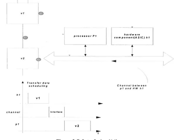
Interfacing
Since the mapping phase separates computing functions onto different processing units, either software or hardware, to execute the particular functions in a program, interfacing focus on how to
communicate data between those units (HW and processor). Usually such communications arc rnapped as some specific channels between HW units
(
or ASICs) and processor. In addition, the extemal tirne for transferring data has to be considered and scheduled to prevent the data conflicts between HW units outputting the data and software functions waiting for the data as input.Figure 2-7 explain the work what should be considered in interfacing phase.
processorPi
À Transfer data
scheduling Channel botween
I plandHWhi hi vi channel interfne pi v2 Figure 2-7 Interfacing
114]
2.4.3 The strategies of partitioning
Various system-level partitioning approaches have been developed to divide the behaviour specification into a set of software processes running on CPUs and co-processors in hardware/software co-design. Two approaches stimulate the interest of researchers: software oriented and hardware-oriented [14].
The Cosyma synthesis tool suite (launched at the University of Braunschweit, Germany)[15] use software-oriented algorithm to partition a computing system into the components mnning on the processor and the components implemented in ASIC hardware, shortening the executing time of
14
overail system. Software-oriented approaches start with a compiled software program, determines the bottlcneck of software and move the bottleneck segments into dedicated hardware coprocessors. The approach is a loop partitioning process to shift critical functions implemented in hardware until ail timing constrains of a computing system are fulfihled [14].
A hardware-oriented algorithm has been introduced by Gupa and Demicheli and applied in the Vulcan synthesis tool suite [14, 15]. The approach starts the initial step to set ail functions onto hardware and meets the perfonnance constraints of a computing system by iteratively moving the functions executed on hardware coprocessors onto the software components running on the processor [20]. Thus, the functions remaining on hardware circuits for synthesis may be implemented on a minimum amount of ASICs hardware with lower cost of the system design. One benefit ofthe approach is to reduce the cost of hardware resource, fulfihling the overail performance constraints of the computing system [14].
2.5
Our work on the hardware/software co-design
Considering commercial profit and time-to-market shortening, design engineers must pay more attention on the reuse of modular software. The research on how to identify the crucial segments in modular software and implement these parts on hardware draws more attention in hardware/software co-design. New approaches dealing with partitioning oforiented-object systems are needed in order that such system can keep the ftexibility of modular programming and gain high performance with the combination of hardware and software. Our work will be concentrated on this aspect ofhardware/software co-design, exploiting the object-oriented paradigm.
We are using the Click router, which inherits the strengths of oriented-object technology such as flexibility and reuse. However, the transferring cost among objects may lower the overall performance ofthe Click system. Software optimization may flot eliminate such cost due to the way in which Click routers process packets (see Chapter 4.3). Therefore, the alternative way of using hardware to implement some function plays a much more important role in accelerating packets processing in network. Thanks to the previous research that D.Quinn, M.Hubin[12] has completed a method on how to build the interface between Click router running on a processor and A SIC
components on StepNP platform (described in Cliapter 4.2) lias been proposed, we ai-e able to develop a system-level approach on how to identify the bottleneck fragments in Click code and move those fragments into hardware components and how to evaluate the performance of network-on-chip (fixed Click inside) in co-design. In fact. DQuinn and MHubin[12] developed a way to create connection hctween hardware parts and software parts in StepNP environment without
discussing how 10 partition and evaluate the whole performance in the whole IPv4 router. We used
their w ay t o do tlie simulation a ndto finish the e valuation on o ur p artilioning a pproach forthc
wliole C lick lPv4 s oftware r outer i n S tepNP p latfonn. M eanwhile. s mcc D .Quinn a nd M Hubin choose a specific Click elernent (ChecklPheader) on a crucial path to implement their rnethod without implementing their method on the other Click clements on different downstream routers. their way may cause deadlock in simulation, wc did some srnall modification on their method (the detail is discusscd in Chapter4.5 section 1).
2.6 Our
partitioning methodology
Our p artitioning ni ethodoÏogy i s created b ased o n ni odel-based co-design (MBC) p erfoniied j n higher abstract 1 evel. M odel-based c o-design
t
MBC) [24] p artitioning r efersto u sing s irnLdationmodeling approaches to explore the way of hardware/software partitioning in co-design. My partitioning methodology is created based on sucli idea. Although more and more CAD tools have been developed, we may flot search for a solution without human users’ guidance in most hardware/software co-design problems [15].
Based on simulation modeling technique as well as analyzing Click code rnanually, we explored a system-level methodology to partition Click application onto hardware/software, implementing a Click JPv4 router on one processor SoC architecture. Given the methodology, we did an evaluation for the performance oftlie entire IPv4 router architecture in hardware/software co-design.
_______________
16
Chapter3
Multiprocessor Concepts
As the computing for embedded systems gets more complicated, those complex computations are distributed onto multiple processes and performed on several processors, with inter-communications links between the processors[21]. Figure 3-1 is a example of the distributed system which includes both a DSP (digital signal processor) handling signal processing and a microcontroller dealing with external user interaction [211.
Furthermore, many embedded systems may perform time-critical tasks, such as real-time transactions. Due to the technique on semiconductor process, the yield of the small size chip is larger than that of the big size chip out of a wafer[30]. Therefore, using a couple of srnall processors including simple operations may cost lower than does using a large processor which contains complex operations[2 1]. Due to the constraints for higher performance and lower cost, the requirements for distributed computing motivate to search for new design approaches oriented to multiprocessor architectures in hardware/software co-design [27].
Also, while designers must handie the more difficult problem about processor parallelism caused by the distributed computing, the current multiprocessor architectures makes the flexibility to add (or cut
)
the number of processors possible and improves the performance of software by distributing computation among multiple processors[27].This chapter will present the following sections. Section 3.1 will concern some current problems on multiprocessor. Section 3.2 will introduce some existing researches on the design of multiprocessor.
3.1 The basic knowledge on multiprocessors
A multiple processors architecture is an architecture defined with the following major features[3 1]: 1) Two or more central processing units (CPUs)
2) Shared memory and shared I/O
3) Hardware and software interact at all levels (including hardware and operation level) 4) Operation system for such architectures
bus interface device interface
CJ)
C) C)
KeyBoard(Z) C) O
Figure 3-1 A distributed system on embedded chip 121]
Given the multiprocessor architecture, some existing problems should be considered: • Basic organization
• Synchronization
• distributed system scheduling • processes partitioning BUS micro controller RAM ROM DSP (Digital Signal
Pro ces sot)
bus inerface
RAM ROM analog-to
digital
J
concerter analog signalreceiver
18
Basic organization
Based on different physical connections, the basic architectures of multiple processors may be classified into two typical categories: a single-bus multiprocessor and network rnultiprocessor[30]. The architecture of a single-bus multiprocessor is depicted in the figure 3-2.
Cache Cache
g
MemoFigure 3-2 A single-bus multiprocessor [30J
By replicating the data in the caches, the caches in the close-processor structure may help to reduce traffic between memory and processors, lowering the communication pressure on the single bus. Single-bus organizations are useful and attractive when the number ofprocessor is not quite large, usually between 2 and 32[30].
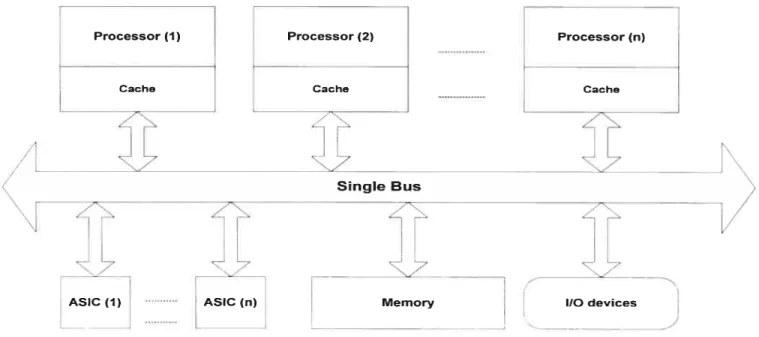
Network multiprocessor: processors are connected by a network [30] depictedin Figure 3-3.
Such structure overcomes the limitation of single-bus designs and may s upport more processors running in parallel, from 8 to 256[30]. Network multiprocessors may use message passing method to exchange data among processors[30].
Processor (1) Processor (2) Cache Processor (n)
t
ASIC (1) ASIC (n) Single BusFigure 3-3 multiprocessor architecture with Network connection
1301
Synchronization
Whcn processors are running concurrently, they may require exchanging or sharing data. Thus, the communication needs to be done to handie the shared resources between the processors. This process is called synclironization or coordination[29, 30]. Sorne efficient techniques are widely used to support this behaviour.
1) Locking
When a processor is working on the shared memory at a time, it locks the memory and other processors that require using the same memory have to wait at that moment until the previous processor releases the shared memory. This process is caÏled locking and unlocking [29, 30].
The goal of locking techniques is preventing write/read conflict in the shared memory. Otherwise, a processor may work on the old data before the previous processor finish updating the data.
2) Message passing
Message passing is an alternative approach to handie how to share the data. This process is similar to the communication on local area network. When a processor as a sender sends a message to the processor as a receiver, the sender notifies the receiver that the message lias been sent out. In
Network
ASIC fi) Memory(i) Memory
(2)1
Cache Gahe
20
response, when the message gets to the receiver, the receiving piocessor wiÏl acknowledge the sending processor that the message has been received. This process is called message passing technique [30]. By this way, the processors may communicate the data between each other.
Distributed system schedulîng
Process scheduling determines when hardware engines(e.g. processors) start to perfonu a process and how the hardware engines use available time efficiently[29]. Process Scheduling definitely affects the overali cost and performance of the distributed system. While making scheduling strategy, designers must consider two major points: the time required to run the process on available processors and the number of processors required to meet time constraints[21]. Usuaiiy, scheduling policies may be divided onto two categories: static scheduling and dynamic scheduling [29].
Static scheduling determine on which processor each process vi11 execute according to existing processors and even the time to run each process when a program is designed. Thus, every process may run on a certain, flxed processor, preventing high overhead if scheduling is perfonned during system execution. However, this method may flot suit the case that the nitrnber ofparallel processes is likely to change at the runtime[29].
Dynamic schedulïng can solve the above mentioned problem since such policy may load or unioad processes ninning on a processor according to the changes of processes at nrntime. Although this policy increases the cost for rescheduling process, it can get better performance when the number of processes in paraliel changes frequently and rapidiy and the cost for swapping the processes is low.
Until now, some important scheduling algorithms have been developed such as single shared ready queue, co-scheduling and dynamic partitioning.
Single share ready queue (SSRQ)
Based on some mies such as FCFS(firs corne first served), SJF(shortest job first or RR(round robin), designers use a queue shared by ail processors to allocate processes onto processors in
SSRQ policy[29].
Co-scheduling
Coscheduling ananges processes to be executed concunently on different processors. Such policy may be suitable to the situation in which processes require frequent data exchange[29].
Dynamïc partïtioning
In dynamic partitioning policy, the processes of a program are dynamically scheduled onto a set of processors chosen from available processors. Then the program periodically checks the number of processes from scheduling server. This number is called “ideal number”, which indicates the processes number with which a program may be executed in an ideal condition. If the ideal number is more than that of processes which are nmning, the scheduler actives previously suspended processes again. If the number of nmning processes is more than ideal number, sorne processes will be suspended to rneet the rnost ideal situation in which the program is executed best [29].
Process partitioning j2lj:
Process partitioning refers to dividing functions without data dependency (one ninning has to wait for another’s output as input) into several smaller processes and ntnning those processes on different processors. Good partitioning might ensure hardware resources (e.g. processors) to be used efficiently and prevent the phenomenon that some processors are very busy at computing and the others are often idle [21]. Such partitioning may shorten the idie time of a processor, speed up the executing time of processes in parallel on different processors and improve the overali performance of software architectures [21].
For example (see Figure 3-4), a process pi includes two functions, which are likely to be partitioned onto two process x and process y before partitioning. Since two functions are executed sequentially, the process p3 that depend on the two values from two functions has to wait a long time, increasing the idle time of processor 3. After process partitioning, process x and process y may run on two different processors concurrently. As a resuit, the computing outcome of two processes x and y may be sent the process p3 earlier than before the partitioning, shortening the idie time ofprocessor p3 [21].
Distrfbuted process allocation [211
Distributed process allocation considers h0W to a ssign a group of processes ninning onto a
processors. For example, in Figure 3-5 (a), processes fi, f2 and f3 require exchanging (messages) frequently. Process f4 has no or a littie data exchange with the other processors [21
V I
Process pi runrnng on the For (i0; For (iO; i<N2;
For(i0; i<Ni;i++) “\ processorpi kNi;i++) i++) I
proc (i,a)
_________
proc(i,a) proc (f, b) I
send (w,a); V_-_ send (w,a); I send (x,b);
Processor process x process y
For (i0; i<N2; i÷+) I pi tend (x,b);
I
/
/
/
process pi
Process p3 depending on the computing results of xw processpi proc(w); r=proc(X); Processor process p3 p3
Process p3 running on the processor p3
Figure 3-4 An example to describe the influence of process partïtioning on distributed system performance 121]
Thus, Wemay consider to arrange fi, f2, and f3 running on the same processor(P1), and f4 rulming
on the processor P2 as depicted in Figure 3-5 (b). Since fi ,f2 and f3 are running on the same processor, We may use much cheaper, faster shared memory as a ay of exchanging their messages. Such allocation may minimize the bandWidth of communication on the link (e.g. bus)
22
Some typical contributions in this research area includes the process partitioning algorithm developed by Huang [21] to minimize the delay betWeen inter-process communication [21], and Ma et al. branch-and-bound algorithrn to reduce the number of processes and inter-process
communication cost.[21j. few data After process partitioning Processorpi Processrp2 ftwhpI3 VJ simultaneously
between processor Pi and P2, reducing bus conflict and improving the whole performance of distributed process allocation[2 1].
The process allocation can be done either under the designer’s guidance or in automated algorithm. The first automated algorithm was developed by Stone[21], but might not suit more than two processors allocation. After the birth of the algorithm, many researchers have continued to developed more approaches on the process allocation. for example, with the help of graph matching heuristic technology [21], Shen and Tsai’s algorithm may effectively allocate the processes running onto the available processors, lowering inter-processor communication traffic to
ED
(a)Before process allocationPI, P2exchange databybus
Processor P2
o
(b)After process allocation
Figure 3-5 how process allocation affects the performance of distributeil computing system [21]
a minimum amount and balancing overall system load [21].
3.2 The related researches on multiprocessors
Nowadays, System-on-chip stimulates much interest of researchers in multiprocessors architecture
24
applications-specific (dedicated applications like embedded systems) multiprocessor system-on chip[27]. Among those research projects, POLIS[14] introduces a target architecture with the combination of general-purpose processors and other possible components such as DSPs and ASICs. CO$Y[14] has developed a layered communication model based on the POLIS approach [27]. CoWare[141 presents a more generic architecture and design flow to help applications specific multiprocessor systems-on-chip design[27]. However, above mentioned approaches have at least two limitations to support various applications-specific multiprocessor systems-on-chip design:
1) Those approaches give the restriction on the use of components, only supporting some specific components. For example, designers can choose only DSP or products with a particular type(MC68000, or ARI\4 7, etc.) [27) in those approaches.
2) Their protocol channel library may offer limited protocol types for communication among components. Only sorne specific components can be connected with the specific
communication link[27].
Given those situations, Amer.B. and Darnie.L introduce a generic model and a methodology to support heterogeneous processors in applications-specific SoC design.
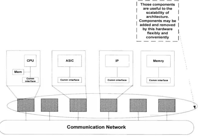
Compared with the above mentioned methods, this approach cornes up with an architecture model on the higher level, a nd gives the more abstract architecture model, which may be the g uide of building more generic platfomis and may be used in much wider application fields without the limitation of components and communication models. For example, StepNP platform is such a practical application project based on the generic model[27], helping network-on-chip design. Figure 3-6 depicts such a generic architectural model.
In multiprocessor architectural model, designer must be concemed with the following three aspects:
Modularity is the nature of oriented-object technology allowing to divide a complex system into some small simple components, which encapsulate specific behaviours. The internai behaviours may not be modified by the outsider directly. Due to the flexibiiity of modules, components may be reused and assembied to support various applications according to different requirements [27].
Components may be software, hardware, and communication network (e.g. chaimel, or bus). Hardware components include processors, memories or particular penpherals. Components inherit the quality of modularity. In this model, processors components may choose various brands of CPU sucli as ARM7 or Mc68000 to constnict heterogeneous systems, meeting various practical SoC designing[27].
A multiprocessor architecture model should be scalable. In such architecture, designers should be able to increase or reduce the number of components to support various application-specific
I
Those components are useful to thescalability of
I
architecture. Components may beadded and removed by this hardware
flexibly and
I
convenientlyMemry
systems [27]. Now components can be CPU or communication channel [27].
In the Figure 5-2 of chapter 5, the architecture for click application on StepNP platform may be regarded as an instance of the generic multiprocessor architecture model. The detail is depicted in chapter 5. Meanwhile, Amer.B. a nd Damie.L present a g eneric methodology on multiprocessor SoC design. The overail design ftow is descried in Figure 3-7.
CPu
Mem
ASIC
L_t0
26
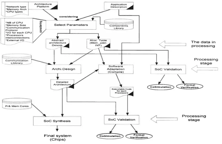
The major steps are introduced as the following:
1. Detenriine hardware architecture with fixed parameters inciuding CPU types, such as ARM7, MC6$OO etc, from the hardware aspect. Consider which process of the application specific should be executed concurrently on the processors fiom the software aspect. These two actions may be taken concurrently.
2 Select parameters such as the number of CPUs, communication protocol for creating high level model.
Furthermore, ail pararneters and next step has been presented in Figure 3-7.
Figure 3-7 the generic design metliodology of a multiprocessor SoC architecture t271
________ The data in çJ 7 processing Processing stage SoC VaIidaton KZ “ItfoniInn ______________ Processing stage
The Se]ect Pararneters process(see Figure 3-7), which focuses on hardware design based on applications-specific parameters, generates abstract architecture description and allocation table.
The abstract architecture is a rough layout of the architecture platform. Allocation table consists of detailed inforniation about architecture, including intemiption levels reserved for each CPU [27]. An allocation table may be used to refine the rough layout into further detailed architecture for SoC synthesis and to detenriine various interfaces including the connection between processors [27].
The work of software design mainly focuses on compiling programs and generating the binary code targeted on each CPU [27].
After the validation on CAD sirnulators, the final resuits of design are generated by SoC synthesis process.
This approach introduces a general guide on how to build an architecture on SoC efficiently and supports the development of various application-specific systems. Designers rnight be able to follow the design flow depicted in Figure 3-7 to complete embedded chip design[27].
3.3 Our work on the multiprocessor
As we mentioned in flic Chapter introduction, modular components router bas benefit on flexibility and extension comparcd with conventional router. Click router is a new architecture to bui]d flexible and coniigurable router with high perfonnance [IÏ. When we analyse the structure of Click software router, wc know that Click configurations are modular and easy to extend [1]. Such structure bas potential parallelism, make it more possible to running Click router on multiprocessor. In addition, Click router rnodularity bas its own llaws and limitation (see the expianation in the opening ofChapter 4). Our work on the multiprocessor focuses on exploring a way to implement the Click router applications system (coded in C++) on multiprocessor.
While considering the hardware design of multiprocessor architecture, researcher must consider whether sofiware applications are available to run in parallel and whether programs can run faster on multiprocessor architecture. In fact, it is even harder to find applications that can perfonn well on multiple processors, taking advantage of such hardware architectures efficiently{30]. Also, designers should consider whether programs can be reused and whether the cost to modify the software for such architecture can be minimized as the number of processors increases[30]. Given
28
the reuse of software, an oriented-object language program presents such strength due to its inherent nature that” describes a highly mobile concurrent system in which new objects are created as computation proceeds and the linkage between components changes as references to objects are passed in communications “[29].
A particular example of the relevant applications is SMP Click router, originated from Click router [11 (the detail inChapter 4.3) and designed for running on multiprocessor architectures. The nature of modularity of SMP Click allows users to write separated configurations, achieving the goal of configuration-level parallelism[2$]. Configuration-level parallelism refers to spiitting a configuration into smaller sub-configurations and executing the sub-configurations on multiple processors concunently.
Due to the cost ofpassing between modules, the Click router may get speed up either with the help of coprocessors or byrunning on multiprocessors in hardware/software co-design. However, it may be difficult to implement SMP Click on multiprocessor network on chip (NoP) co-design for the following reasons:
1) The expensive cost for CPU scheduling on the centralized task queue of elements makes the Click designers choose the private a task queue of elements for each separated threads running on different processors. However, since SMP Click inherits the CPU scheduling of Click (see the feature 3 in Chapter 4.3.2), such scheduling scheme may it difficult to determine the running time for the element on different processors. Thus, it may take place that one processor is very busy, and others are idie. How to balance processors resource becomes a problem that need to be solved [2$]
2) Now that SMP Click use separated threads for different processors, designers must consider how to create shared locking to synchronize the data exchange between processors. That increases the complex of handling the packets communication between different processors [28].
Click router on multiprocessor SoC architecture. Meanwhile, The structure of modularity contributes large flexibility to Click router, making it possible to implement the approach.
3.4. Our methodology for Click implementation on multiprocessor
SlMicroelectronic has developed a simple multi-threaded processor architecture on which a hardware thread executes the overail Click application with the different or same configuration files. In their case, there are very few data dependency and data exchanges between the different threads executing the Click application. This approach is called inter-packet processing level[26]. Our approach focuses on using multiple ARM processors to proccss a single packet with possible high inter-block dependencies [26], implernenting the configuration-level parallelism [28]. In other words, the Click application will be partitioned on the different processors ofthe architecture.
With the guidance of the generic architectural model, we have explored a system-level design approach on how to implement Click router with multiple processors and evaluated the method on the StepNP simulator. The detail ofthe method will be introduced in Chapter 5. The approach may
be considered as a contribution on how to design a suitable multiple processors SoC architecture to mn programs written in orientcd-object language (e.g. C++).
30
Chapter4
HardwarelSoftware Co-Design Methodology on
Partitionïng
Although the Click element (the detailed in section 4.3) lias flexibility and scalabifity for various router requirements, sucli modular element causes the cost of performance on processing packets in two-folds:
1) the modularity of elements brings about the expense for passing packets between elements in flow chart of Click router configuration [I]. For example, one of the three virtual functions such as sirnple_action(Packet *p), pull(int port number) or push(int port ntimber, Packet *jj) in each element (or C++ object) must be called when a packet is forwarded
from one element to next element along the processing path in a Click configuration. A virtual function cal! must cost certain CPU tirne. According to a experirnental resuit on Click performance, the cost to pass a packet between two elements is about 70 ns{l] and the passing the sixteen elements in a regular Click IP configuration costs about I ms[l] in total. 2) the modular structure may inevitably increase the cost of passing packet since the Click
router has to cal! sorne elements with the general functionality [1]. A typical example is the element named “Classifier”, which includes the generic functions that may flot be used for IP Click router. $ome generic functions are flot tailored to some specific applications of IP Click router when software writers may consider its multiple usages for various Click router applications. Thus, given the usage in Click IP router, such general element codes may cause unnecessary overhead, costing more CPU time[1J.
Those features are inherent in Click application software and the overheads may be very difficult to be prevented in Click software. To counteract these costs, using H/W co-design methodology is a feasible choice. The Methodotogy is implemented on StepNP platform.
4.1 The general presentation for methodology
Now that my research concentrates on system-level partitioning process with the help of using simulation tools and rnanually analyzing source code together, my work focuses on the approach from three aspects: hardware, software, and simulation platform.
Simulation P]atform:
We choose StepNP platform as our simulation platform. Section 4.2 presents the stntcture of StepNP platforrn in detail.
Hardware:
Based on StepNP simulation platform, we use systemC’ modeling language to design the hardware units for computational system, to implement the system-level partitioning, the performance analysis and the evaluation on Click JPv4 router.
Software:
Our software mainly concentrates on an open source code: Click rotiter application. STMicroelectronic cornpany has rnodified the source code targeted to ARM7 processor SoC architecture.
Section 4.3 will introduce the working principle of Click IPv4 router and the basic knowledge of Click router application in detail. Section 4.4 introduces how to move crucial software segments onto hardware implementation partitioning. After creating a hardware architecture in SystemC, we may analyze the modeling result of simulation and identify the bottleneck code segments for partitioning. Section 4.5 describes the hardware algorithm in SystemC and the way on how to
SystemC is a modeling language that is derivative from C++ libraries and may be used to design both hardware and software. If hardware and software are designed based on oriented-object technology, the system-level co-simulation of HW/SW may be completed more easily in the environment to support SystemC. In addition, some synthesis tools such as CoCentric(R) SystemC compiler also can implement hardware synthesis in the lower level.
32
communicate between the SysternC hardware modules and the software modules in C++ oriented object language.
In our research, we modify Click software, design hardware, build simulation platform and adjust these three aspects iteratively until the constrains for the application system are reached. $ince the executable specification of Click application has been defined and completed in oriented-object C++ language, the co-simulation between Click and the SysternC hardware units may be done more easily on high-level. Figure 4-1 depicts the general outiine of the rnethodology.
Someelements areimplemented
on hardware coprocessors
L0OkUPRT DecTPTtL lPFragment HWModule HWMoUule
Module StrlpHW CheckSum
Mdule HWModuIe
SOCPlnterConnect
i-1w architecture Application: Click
Architecture: StepNP
First, we created the cycle-accurate executable architecture in Figure4-1 by modifying the existing simulation platforrn in StcpNP tool kits. Then, ninning each element of Wv4 router configuration in the ARM processor of the architecture, we applied simulation to count the executing cycles of each element, which show the complexity of each part of Click IPV4 code. Thus, we were able to identify bottleneck fragments that cost many cycles and map those critical operations onto co processors tailored for the given architecture (here is ARM) iteratively [19].
With the support of StepNP platform, the approach may build the executable application-specific architecture easily and complete partition process efficiently based on the combination of user guide and sinnilation evaluation, shortening the time and efforts in hardware/software co-design.
4.2 StepNP platform introduction
First, we introduce the principle of StepNP platforrn, which is a System-level Telecom Experimental Platform[61 running on Unix-like OS for Network Processing. StepNP modeling supplies an approach to support top-down co-design verifications methodologies and to reduce the tirne and efforts spent on system-level partitioning stage. StepNP offers existing components libraries for designers to model hardware components and to create a system-level model frarne for simulation validation and evaluation. StepNP platforrn contains three components i-elevant to ARM RISC processor.
1) MIT Click Router Platform in StepNP
StepNP h as d eveloped s orne p atches to MIT C lick r outer (user-model) for A RIVI s imulator, and supplied some new elements as the interfaces to support ClickTs running on ARIVI simulator.
Thus, the user-module configuration for MIT Click router can running on StepNP’s ARIvI simulator. Two new added elements are FwidlSink which injects packets frorn Unix platforrn into the address in StepNP, and FwidlSource which reads packets from the address in StepNP platform. These two elernents establish a bridge between the internal environment of StepNP platform and extemal processing system or operation system platform.
34
2) SoC tools platform
SoC tools platform is classified two categorics: 1) tools for developing embedded system on a single processor, including an instruction-set simulator , a compiler, etc. 2) tools for developing
computing system over multiprocessors, including controlling, debugging and analyzing functionality[6].
3) NPU architecture simulation platform
The three major components of the NPU architecture simulation platform include modeling language( using SystemC 2.0), rnultithreaded processor mode! and a SOCP( SystemC Open Core Protocol) communication channel interface[6].
Using an existing ARM processor components as a master and SOCP communication channel, we can build a simple master-slave testing architecture
t
called simplePacket platfonn shown in Figure 4.2) to support the simulation of Click router for ARM CPU. Then, we choose a collection of the elernents in Click and test it on the simplePacket platform.Wç
C-H-$ÂNP
InrfaœsWth
e4emalernironnent
4.3 Click router
Click router is a typical oriented-object application system developed by Eddie Kohier in MIT. Most router systems have predetermined, fixed functions often implemented on hardware(or ASIC’s) before they are launched into thc market. Thus, such routers leave littie room for an administrator to configure routers flexibly to meet some particular requirements and to add new functions in route?s configuration to support new protocol or new network development [1]. The software based [4]
(
means implementing most functions in software)
Click router is a configurable architecture for packet forwarding processing to prevent those disadvantages. Click router has about 60 major elements to support various router configurations. Each element implements specific functions in packet processing. Depïoying the Click router elements with connections(
explained in section 4.3.1 in detail), the tisers may build a router configuration- the collection ofthe elements- 10 support the desired behaviors.In fact, the Click “element” is the object of the C++ class. Sorne of the elernents are virtual classes. According to the inheritance attributes of C++ class. Click router has two typical features aboitt router configuration:
1. Based on existing elements or virtual classes, users may develop some new elements to extend Click functionality. After they write a new C++ object with the new functions, users are able to add the new object into Click router conveniently according to the approached taught by Click router developers. Thus, the new elements may combine with the old ones to build varions configurations, supporting desired complex applications[ 1].
2. An element implements various functions based on the concept of C++ polymorphism. for example, RED(Random Early Detection) can behave as RED over multiple queues, weighted RED, or drop-from-front RED according to the different requirements ofpacket processing[1].
4.3.1 Click router element connection
The graphic edges among elements in a configuration diagram are called connections used to forward packet between the elements. Each element may have the multiple ports for exit to connect itself 10 the other element’s port for entrance[ 1].
![Figure 2-1 Hardware/software co-design framework 114, 22]](https://thumb-eu.123doks.com/thumbv2/123doknet/7527149.227277/18.918.100.852.102.798/figure-hardware-software-co-design-framework.webp)
![Figure 2-3 a typical multiprocessor architecture 124]](https://thumb-eu.123doks.com/thumbv2/123doknet/7527149.227277/19.918.97.787.658.1037/figure-a-typical-multiprocessor-architecture.webp)
![Figure 3-1 A distributed system on embedded chip 121]](https://thumb-eu.123doks.com/thumbv2/123doknet/7527149.227277/30.918.117.848.336.801/figure-a-distributed-system-on-embedded-chip.webp)

![Figure 3-4 An example to describe the influence of process partïtioning on distributed system performance 121]](https://thumb-eu.123doks.com/thumbv2/123doknet/7527149.227277/35.918.134.783.345.835/figure-example-influence-process-partïtioning-distributed-performance.webp)
![Figure 3-5 how process allocation affects the performance of distributeil computing system [21]](https://thumb-eu.123doks.com/thumbv2/123doknet/7527149.227277/36.918.144.718.395.774/figure-process-allocation-affects-performance-distributeil-computing.webp)