HAL Id: hal-00585526
https://hal.archives-ouvertes.fr/hal-00585526
Submitted on 13 Apr 2011
HAL is a multi-disciplinary open access
archive for the deposit and dissemination of
sci-entific research documents, whether they are
pub-lished or not. The documents may come from
teaching and research institutions in France or
abroad, or from public or private research centers.
L’archive ouverte pluridisciplinaire HAL, est
destinée au dépôt et à la diffusion de documents
scientifiques de niveau recherche, publiés ou non,
émanant des établissements d’enseignement et de
recherche français ou étrangers, des laboratoires
publics ou privés.
Modeling the trajectory of a micro particle in a
dielectrophoresis device.
Mohamed Kharboutly, Michaël Gauthier, Nicolas Chaillet
To cite this version:
Mohamed Kharboutly, Michaël Gauthier, Nicolas Chaillet. Modeling the trajectory of a micro particle
in a dielectrophoresis device.. IEEE International Conference on Robotics and Automation, ICRA’10.,
May 2010, Anchorage, Alaska, United States. pp.4125-4130. �hal-00585526�
Modeling the trajectory of a micro particle in a dielectrophoresis device.
Mohamed Kharboutly, Micha¨el Gauthier and Nicolas Chaillet
Abstract— Micro and nano-particles can be trapped by a non uniform electric field through the effect of dielectrophoretic principle. Dielectrophoresis (DEP) is used to separate, manip-ulate and detect micro particles in several domains, such as in biological or Carbon Nano-Tubes (CNTs) manipulations. Current methods to simulate the trajectory of micro-particles under a DEP force field are based on Finite Elements Modeling (FEM) which requires new simulations when the electrodes potentials are changed, or on analytic equations which are limited to very simple geometries. In this paper, we propose an hybrid method between analytical and numerical calculations able to simulate complex geometries and to easily change the electrode potential along the trajectory. In this method a few FEM simulations are used to create a database which enables online calculation of the object trajectory in function of the electrode potentials. In order to verify the simulation results, experiments are done and compared to the simulations.
I. INTRODUCTION
Manufactured products become always smaller and inte-grate more and more functionalities in small volumes. Sev-eral application fields are concerned such as bio-engineering, telecommunications or in a more general way Micro-Electro-Mechanical-Systems (MEMS). The assembly of these mi-croproducts is a great challenge because of the microscopic size of the components. In fact, the major difficulties of assembly come from the particularity of the micro-object’s behaviours which are more function of the surface forces than the volumic forces [1], [2], [3]. The manipulation of a micro-object requires its handling, positioning, and release without disturbances of the surface forces such as electrostatic forces, van der Waals forces or capillary forces. The release is the most critical phase which is usually perturbed by adhesion phenomenon.
Several methods have been proposed in the last ten years to improve micromanipulations [4], [5]. The first approach deals with contact manipulation where the adhesion should be reduced or could be directly used for manipulation [6], [7], [8]. The release requires innovative methods overcome adhesion. Dielectrophoresis force, which is the force applied on a polarizable particle in a non uniform electric field, has
M. Kharboutly is with FEMTO-ST institute CNRS UFC/ENSMM/UTBM Automatic control and Micromechatronic System Department 24 rue Alain Savary, 25000 Besanc¸on, France
mohamed.kharboutly@femto-st.fr
M. Gauthier, Membre, IEEE is with FEMTO-ST institute CNRS UFC/ENSMM/UTBM Automatic control and Micromechatronic Sys-tem Department 24 rue Alain Savary, 25000 Besanc¸on, France
michael.gauthier@femto-st.fr
N. Chaillet, Membre, IEEE is with FEMTO-ST institute CNRS UFC/ENSMM/UTBM Automatic control and Micromechatronic Sys-tem Department 24 rue Alain Savary, 25000 Besanc¸on, France
nicolas.chaillet@femto-st.fr object properties tensions database geometries FEM simulation Analytic expression trajectory Hybrid simulation trajectory object properties tensions FEM model Classic FEM simulation geometries
Fig. 1. General principle of classic FEM simulation and hybrid simulation
been recently used to induce a repulsive force on micro-objects in order to release them [9]. The second approach consists in using non-contact manipulations as laser trapping [10] and dielectrophoresis [11]. These principles are not disturbed by adhesion but the blocking force remains low.
In this paper we simulate the 3D behavior of micro par-ticles under DEP force. This force is calculated in function of the electric potential applied on the electrodes. Using the vision capture, the control law of the system can be studied and a first step to a closed loop is proposed. The typical problem at this scale is the large difference between the high
dynamics of the system (response time ≃1ms) and the low
speed rate of the vision capture (≃1 image per 10 ms).
Thus, we propose to design a predictive control strategy based on the feedback of the vision sensor and a model of the DEP force. The introduction of a model will enable to control the object behavior despite the low speed rate of the vision capture. This paper is focused on the presentation of the model.
Because of the large variety of electrodes and their ge-ometric complexity, it could be highly difficult to directly integrate analytic equations. Our method is based on merg-ing preprocessed FEM simulations and analytic equations. Physical equations are computed in order to define the link between the electric potential and the DEP force.
Consequently, based on the database built by several preparatory FEM simulations, our simulator is able to pro-vide the trajectory whatever the electric potentials applied on the electrodes (see Fig.1). This approach enables to improve the simulation’s time. Each iteration consists of the use of the equations linking the electric potential to the electric field and then to the DEP force. FEM software can simulate complex geometries but the simulation time remains high especially when the potential changes frequently. By using
FEM simulator as a preprocessing simulation and integrating physical law in a specific simulator, the time of simulation can be highly reduced. In the next section, a numerical implementation of how to calculate the electric field in function of the electric potential applied on the electrodes are discussed. In the third section the principle of the dynamic model is presented and in the fourth section, simulations and experiment results are shown and discussed.
II. CONCEPT OF HYBRID SIMULATION
A. General principle
The general expression of the dielectrophoretic force ap-plied to a micro object considered as a punctual point [12], [13] is: −−−→ FDEP = 2πǫ0ǫpr 3 Re[K(ω)] −−→ ∇E2, (1)
where K(ω) is the Clausius - Mossotti factor:
K(ω) = ǫ ∗ p−ǫ∗m ǫ∗ p+ 2ǫ∗m , (2) and ǫ∗= ǫ + σ jω, (3)
where ǫ are the permittivities, σ are the conductivities, index
0 refers to the vacuum, index m refers to the medium and
index p refers to the micro object, r is the radius of the bead, ω is the angular frequency of the applied electric field, −
→
∇ is the gradient operator and E is the root mean square magnitude of the sinusoidal electric field. This paper focuses on the simulation of the trajectory of a spherical object in a non phased sinusoidal electric field where the DEP torque can be neglected. The DEP force is thus function of the
magnitude of the electric field−→E , and of the frequency ω of
the electric field which modifies the value of the Clausisus - Mossotti factor (2). The first challenge is to determine the
spatial electric field−→E according to the potentials applied on
the electrodes (see Fig.2). Let us consider the magnitude of the sinusoidal electric potentials applied on n+1 electrodes:
[ϑ0, ϑ1, · · · , ϑn] . (4)
The 3D calculation of the electric field−→E with respect to the
potentials (4) is quite complex. Analytic calculations is in the general case not possible because of its too high complexity. To get over this difficulty we use numeric simulations. The proposed idea consists in simulating the 3D behavior of micro beads under DEP force with the minimum of numeric simulations. Firstly, we consider n potential differences:
U = [U1= ϑ1−ϑ0, · · · , Un= ϑn−ϑ0] . (5)
The first goal is to find the relation between the electric
field−→E in a point M (x, y, z) and the potential difference U
applied on these electrodes. This relation can be written as follows: − → E (x, y, z) =−f→E(U ). (6) ( ( , , )) E M x y z dq 2 3 0 1
Fig. 2. Calculating→E for the 2D charge density
B. Numerical implementation
Different methods exist to numerically calculate the elec-tric field. A tridimensional meshing of the space and a bidi-mensional meshing of the electrodes have been considered.
The difference between this 2 methods is analyzed in [16]
and the relevance of electrode meshing is shown. Our study is consequently based on the bidimensional electrode meshing. In this case, the electrodes are meshed along two directions
x and y using respectively ex and ey as the number of
elementary steps through each direction (see Fig.2). The
electric field−→E is the sum of contributions of the elementary
charges Qr,s on the electrode surface at point P(r, s) (see
Fig.3). The electric field at point M(x, y, z) is thus: − → E (x, y, z) = 1 4πǫm ex X r=1 ey X s=1 Qr,s. −−−−−−−−−−−−→ P(r, s)M (x, y, z) −−−−−−−−−−−−→ P(r, s)M (x, y, z) 3ds, (7)
where ds is the elementary surface on the meshed electrode.
To calculate Qr,s, the superposition principle on the
po-tential is applied: Qr,s= n X m=1 Cr,s,m.Um, (8)
where Cr,s,mrepresents the elementary capacitances which
can be identified during preprocessing. Thus the relation
between the electric field−→E and the potential differences U
applied on the electrodes is: − → E (x, y, z) = 1 4πǫm ex X r=1 ey X s=1 −−−−−−−−−−−−→ P(r, s)M (x, y, z) −−−−−−−−−−−−→ P(r, s)M (x, y, z) 3. n X m=1 Cr,s,m.Umds. (9)
The Cr,s,mmatrix contains the elementary capacitances
cre-ated by each potential difference. The electrodes are meshed
into 2D (ex, ey) elementary points on the surface of each
electrodes and the elements of this matrix are calculated using 3D simulation. The equation (9) enables calculating
the electric field vector −→E in any point M (x, y, z) in the
P(r,s)
y x
ds
Fig. 3. Elementary charges in each electrode
Q (x,y,z) FDEP C (FEM) U ds ∇2(E) Preprocessing Numerical computation 2 0 rr3K( ) M(x,y,z)
Fig. 4. Block diagram representing the link between the electric potential Uand the DEP force
C. Preprocessing
The capacitance matrix C defined in (8) is constant and is independent from the electric potential U and the charge density Q. To identify this matrix, n FEM simulations of the charge density on the electrodes in function of n algebraically independent vectors U are needed. Once the matrix C is calculated the relation between the electric field −
→
E and the electric potential U is obtained through equation (9).
D. Static force model
The diagram presented in the Fig.4 shows the procedure to calculate the DEP force in function of the potential difference U . During preprocessing, geometries, boundaries conditions and surroundings properties are specified in a FEM software and n simulations are launched. All data are arranged to create the capacitance matrix C. The link
between the electric potential U and the electric field −→E is
then calculated. Thus the DEP force −−−→FDEP applied to the
micro object can be obtained by using (1). The frequency ω of the electric field can also be modified during the trajectory simulation.
III. DYNAMIC TRAJECTORY MODELING
Let us consider a micro particle immersed in a liquid medium with a dynamic viscosity µ, in a non uniform electric field created by applying electric potential on the electrodes.
The forces applied on this particle are−−−→FDEP, its own weight
− →
P and the Stockes drag force−F−−drag→which verifies:
−−−→ Fdrag = −6πµr − → V = −kµ − → V (10)
where −→V is the velocity of the particle. Using Newton’s
second law the particle’s motion is defined by: −−−→ FDEP + − → P − kµ − → V = M−→a (11) Q (x,y,z) FDEP C (FEM) U ds ∇2(E) Preprocessing Numerical computation 2 0 rr3K( ) + 1/k V dt P M(x,y,z)
Fig. 5. Block diagram representing the dynamic modeling of a bead under DEF force
where M is the mass of the particles and −→a is the
accel-eration vector. In order to simulate this trajectory model,
we have proved that the inertia M−→a is a negligible volumic
effect in the micro-world compared to the force [16]. Despite the fact that the weight is a volumic effect it can not be neglected. Indeed the equilibrium state is characterized
by −−−→FDEP =
− →
P , and without considering the weight, the equilibrium position is always toward z ∼ ∞. But, in fact, experimentally the micro particle stands on a finite and stable position.
A. Dynamic model
As the inertia can be neglected, the equation (10) gives the velocity of the micro particle along the trajectory:
− → V = ( −−−→ FDEP + − → P) kµ . (12)
In the Fig.5, a block diagram is presented to illustrate each part of the system acting between the electric potential U , the DEP force and the micro particle’s position. An applied potential difference U on the electrodes creates the non
uniform electric field−→E which creates the DEP force used to
manipulate the micro particle. The equation (12) manages the dynamical behavior of the micro particle under DEP force.
IV. SIMULATIONS AND EXPERIMENTS
Considering the geometry of the electrodes described in
Fig.6, 4 electrodes and 3 potential differences are used.
After3 simulations under the FEM software COMSOL, the
matrix C is identified as described below, and the simulator
is launched. For a silicon bead of radius equal to50µm,
sub-merged in the water, its motion under DEP is simulated from
an initial position (x = 10µm, y = −10µm, z = 55µm)
as it is proposed in Fig.6. Applying the potential difference
U(80V, 0V, 80V) from equation (5) between the electrodes
using a frequency of40KHz the Clausius - Mossotti factor
k(ω) referred in (2) is equal to K(ω) = −0.4252, the DEP force is negative and the trajectory of the bead can be predicted.
A. Trajectory of a point-shaped object
If we consider the object as a point shaped object, there is no presence of the equilibrium state along the z axis (see Fig.8). In the first phase of the motion, the bead goes
-100 m Initial position 100 m 100 m 100 m y x 0 1 2 3 z 10 m 10 m
Fig. 6. Geometry of 4 electrodes studied and the initial position of the micro particle in simulation
0 0.1 0.2 0.3 0.4 0.5 0.6 0.7 0.8 0.9 1 x 10⁻³ -1 -0.8 -0.6 -0.4 -0.2 0 0.2 0.4 0.6 0.8 1x 10 -5 Time(s) C e n tr e p o si tio n (m ) X position Y position
Fig. 7. x, y trajectory of the punctual micro particle under DEP force
2 4 6 8 10 12 x 10-4 5 5.1 5.2 5.3 5.4 5.5 x 10⁻⁵ Time(s) C e n tr e p o s iti o n (m ) Z position
Fig. 8. z trajectory of the punctual micro particle under DEP force
100 m
Micro
bead
Electrodes
x
y
Fig. 9. Vertical view: Electrodes used in the experiments. The micro particle is in the center of electrodes. The applied tension is U(80V, 0V, 80V)
y z Micro bead 100 m Micro bead 100 m Micro bead 100 m y z z =0 z =0 Reflected image Reflected image
Fig. 10. Lateral view: The micro bead is in direct contact with the electrodes plane (Left view) when applying a tension of U(60V, 0V, 60V). The micro particle is in levitation up to the electrodes (Right view) when applying a tension of U(80V, 0V, 80V).
up when it moves toward the z axis. After reaching the equilibrium point in the XY plane (see Fig.7), the bead starts the sedimentation phase and goes down. This motion is caused by the calculated DEP force, which is equal to zero on the micro particle’s center. However, experiments performed on this geometry, using electrodes made from gold and deposit on a silicon wafer immersed in an ultra
pure water and using a glass bead of radius equal to50µm
as a micro object, show that an equilibrium point exists in the center of the electrodes (see in Fig.9) along the z axis (see in Fig.10). In this figure, the micro bead and its reflexion on the wafer are shown on a lateral view. In the left view, the micro bead is on the wafer when an electric potential of U(60V, 0V, 60V) is applied. In this case, the z component of the DEP force is smaller than the weight of the micro bead. In the right view, the micro bead is in levitation above the electrodes plane when an electric potential of
U(80V, 0V, 80V) is applied. This difference between the
experimental result and the simulated result appears because the hypothesis used in (1) (micro particle is considered as a punctual point) is not available in the equilibrium point. This assemption induces a zero DEP force while the real force is not zero.
ci c FDEP c c ci DEP F =0
Along the axe Z
DEP F ≠0
Along the axe Z
z z
Fig. 11. Use of the punctual bead (left), use of the volumic particle(right). Only z component of the electric field is presented
0 0.2 0.4 0.6 0.8 1 1.2 1.4 1.6 1.8 2 x 10⁻³ -1 -0.8 -0.6 -0.4 -0.2 0 0.2 0.4 0.6 0.8 1x 10 -5 Time(s) C e n tr e p o si tio n ( m ) X position Y position
Fig. 12. x, y trajectory of the volumic particle under DEP force
B. Trajectory of a volumic object
To solve this problem, the micro particle is divided into 4 identical parts around its vertical axes and then all forces applied on each part are calculated to find the general force by summing all forces together (see Fig.11). Fig.12 and Fig.13 show the trajectory of the micro particle using the same initial conditions as above. Using this method, the simulated trajectory of the micro particle convinces more with the real trajectory and the simulation results show that the micro particle reaches an equilibrium point as observed in the experimental results.
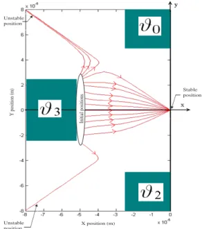
Using our simulator, non linear trajectories can be simu-lated. Multi initials positions of a micro bead of radius equal
to 10µm, under the same potential (U = 80V ), could be
simulated and the projection on xy plane of the resulted trajectories are presented in figure 14.
C. Experimental validation
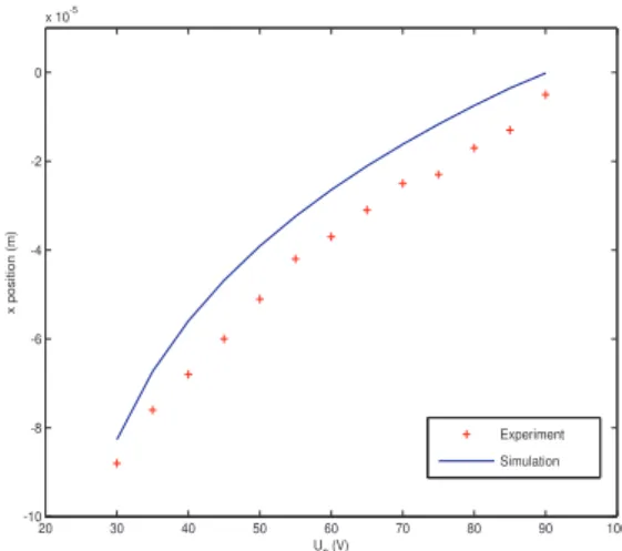
Using another geometry of electrodes described in 15, the
static position of the micro particle of radius equal to45µm,
immersed in an ultra pure water, is calculated in function of the applied tension on the electrodes in both simulation and
experiment. The applied tension is U(90V, 0V, U3). When
changing U3 from 30V to 90V the static position of the
0 0.005 0.01 0.015 0.02 0.025 0.03 5.5 5.6 5.7 5.8 5.9 6 6.1 6.2 6.3 6.4x 10 -5 Time(s) C e n tr e p o s it io n (m ) Z position
Fig. 13. z trajectory of the volumic particle under DEP force
Unstable position Y pos it ion ( m ) X position (m) Stable position Unstable position Ini tia l po si tion s
Fig. 14. Projection of non linear simulated trajectories in the (x,y) plane
-150 m -150 m 150 m 150 m 200 m y x 0 1 2 3 z
Fig. 15. Geometry of 4 electrodes used to experiment the DEP force in the static model
20 30 40 50 60 70 80 90 100 -10 -8 -6 -4 -2 0 x 10-5 U3 (V) x p o s it io n ( m ) Experiment Simulation
Fig. 16. static position of the micro particle in function of the applied tension on the electrodes
micro particle changes. The Fig.16 shows the static position of the simulated calculation and experimental position. In
this figure, it is evident to find that when U3 = 90V , the
static final position is in the center of the electrodes. The difference between the experiment result ans the simulation is due to, firstly the deformed electrodes in the experiments and secondly the transformation from pixel to µm of the bead position in experiments.
V. DISCUSSION
Using a calculator with relatively high performance (Intel Xeon CPU 1.60 GHz (2 CPUs) with 3 GB of RAM) the measured time to simulate the electric field and calculate the DEP force applied on a particle using the electrodes described in Fig.9 and its trajectory under the FEM software COMSOL 3.5 is 2 minutes.
Using the same calculator to simulate the charge density on the electrodes is 30 seconds. To create the base used in
our simulator we need 3 FEM simulations witch means 1
minute30 seconds.
Using this database, the time needed to calculate the trajectory is 10 seconds.
Thus comparing both methods, the time needed to simulate n trajectories of a micro object by applying n different tensions on the electrodes is:
1) For the FEM software:2 × n minutes.
2) For our simulator: 1 minute 30 seconds + 11 × n
seconds.
Consequently, our approach, based on the use of FEM as a preprocessing, enables to clearly reduce the time of computation especially when different values of tension U have to be simulated on the same geometry. However, in this simulator, the calculated electric field is not limited in the space, it can be calculated in any point in the space contrary to the FEM software, where the space is limited to the meshed volume. Moreover this simulator does not take into account the DEP torque, but the general principle proposed here can be extended to angular positioning. This aspect will be explored in future works.
VI. CONCLUSION
We have proposed a new model and simulator using a hybrid method in which we combined both analytic and numeric calculation to simulate the behavior of a micro bead (spherical object) under DEP force. A pre-simulation under FEM software allows to obtain a database with respect to the electrode geometries. Based on the preprocessing, the simulator integrates the dynamical behavior equation to simulate the electric field under different tensions applied
on the electrodes. An example of 4 electrodes have been
discussed and compared to experiments. Current works are focused on the use of this model to study control laws able to move the micro particle along a specified trajectory.
VII. ACKNOWLEDGMENTS
This work is supported by the French research projects
PRONOMIA N: ANR 05 − BLAN − 0325 − 01 and
NANOROL N: ANR07 − ROBO − 0003 − 01.
REFERENCES
[1] P. Lambert. Capillary Forces in Micro-assembly. Springer, 2008. [2] M. Gauthier, S. R´egnier, P. Rougeot, and N. Chaillet. Forces
anal-ysis for micromanipulations in dry and liquid media. Journal of Micromechatronics, 3(3-4):389–413, Sept. 2006.
[3] Q. Zhou, B. Chang, and H. N. Koivo. Ambient environment effects in micro/nano handling. In Proc. of the Int. Workshop on Microfactories, pages 146–51, Shangai, China, October 2004.
[4] Veikko Sariola, Quan Zhou, and Heikki N. Koivo. Hybrid microhan-dling: a unified view of robotic handling and self-assembly. Journal of Micro - Nano Mechatronics, 4(1-2):5–16, 2008.
[5] Pierre Lambert. A case study of surface tension gripping: the watch bearing. J. Micromech. Microeng., 16:1267–1276, 2006.
[6] David H´eriban and M. Gauthier. Robotic micro-assembly of mi-croparts using a piezogripper. In Proc. of the 2008 IEEE/RSJ International Conference on Intelligent Robots and Systems, pages 4042–47, Nice, France, 2008.
[7] P. Lambert and S. R´egnier. Surface and contact forces models within the framework of microassembly. International Journal of Micromechatronics, 3(2):123–157, 2006.
[8] W. Driesen, S. R´egnier, and J.M. Breguet. Micromanipulation by adhesion with two collaborating mobile micro robots. Journal of Micromechanics and Microengineering, (15):259–268, 2005. [9] M. Gauthier, E. Gibeau, and D. H´eriban. Submerged robotic
micro-manipulation and dielectrophoretic micro-object release. In proc. of the IEEE ICARCV 2006 conference, Singapour, dec. 2006.
[10] Kishan Dholakia, Peter Reece, and Min Gu. Tutorial reviewoptical micromanipulation. Chem. Soc. Rev., 37:42 – 55, 2008.
[11] T. P. Hunt and R. M. Westervelt. Dielectrophoresis tweezers for single cell manipulation. Biomedical Microdevices, 8(3):227–230, 2006. [12] F. T. Chang, Y. C. Lee, and C. C. Chiu. Multiple electrodes arrayeed
dielectrophoretic chip with application on micro-bead manipulation. In Proceedings of the 3rd IEEE Int. Conf. on Nano/Micro Enhineered and Molecular Systems, pages 850 – 853, Sanya, China, january 2008. [13] P. R. C. Gascoyne and J. V.Vykoual. Dielectrophoresis-based sample handling in general-purpose programmable diagnostic instruments. IEEE Sensors Journal, 92(1):22 – 42, January 2004.
[14] T. B. Jones. Electromechanics of Particles. Cambridge University Press, 1995.
[15] H. M. and N. G. Green. AC Electrokinetics: Colloids and Nanoparti-cles. Hertfordshire: Research Studies Press, 2003.
[16] Mohamed Kharboutly, Michael Gauthier, and Nicolas Chaillet. Mod-eling the trajectory of a micro particle in a dielectrophoresis device. Journal of Appl. Phys. Submitted paper, 2009.