HAL Id: hal-00797992
https://hal.archives-ouvertes.fr/hal-00797992
Submitted on 7 Mar 2013
HAL is a multi-disciplinary open access
archive for the deposit and dissemination of
sci-entific research documents, whether they are
pub-lished or not. The documents may come from
teaching and research institutions in France or
abroad, or from public or private research centers.
L’archive ouverte pluridisciplinaire HAL, est
destinée au dépôt et à la diffusion de documents
scientifiques de niveau recherche, publiés ou non,
émanant des établissements d’enseignement et de
recherche français ou étrangers, des laboratoires
publics ou privés.
Product Lifecycle Management Model for Design
Information Management in Mechanical Field
Julien Le Duigou, Alain Bernard
To cite this version:
Julien Le Duigou, Alain Bernard. Product Lifecycle Management Model for Design Information
Management in Mechanical Field. 21st CIRP Design Conference, Mar 2011, Daejeon, South Korea.
pp.207-213. �hal-00797992�
CIRP Design Conference 2011
Product Lifecycle Management Model for Design Information Management in
Mechanical Field
J. Le Duigou, A. Bernard
Ecole Centrale de Nantes, IRCCyN, 1, rue de la Noë, BP 92101, 44321 – NANTES Cedex 3 - France [email protected], [email protected]
Abstract
Product Lifecycle Management (PLM) is one way to improve productivity in all manufacturing companies and this is truer in mechanical Small and Medium Enterprises (SMEs). Nevertheless the implementation of a PLM system is not an easy thing for such companies. SMEs have lots of difficulties to create the right information model in order to improve design efficiency. In this paper we propose a PLM model that could help SMEs in the mechanical engineering field. Based on a literature review and on the analysis of the mechanical SMEs needs that would favour efficiency during the design process, a new PLM model for mechanical SMEs is proposed.
Keywords:
Product Lifecycle Management, Product Process Organisation Model, Unified Modelling Language
1 PLM IN MECHANICAL SMES
Product Lifecycle Management (PLM) is “a strategic business approach that applies a consistent set of business solutions in support of the collaborative creation, management, dissemination and use of product definition information across the extended enterprise from concept to end of life - integrating people, processes, business system, and information” [1]. It provides improvements in information search, reuse, change management, etc. And those functionalities are required by the mechanical SMEs according to a 2007 survey [2]. Mechanical SMEs have difficulties to implement PLM systems. As explained by [3], the main difficulty is the modelling of the information and the formalisation of the processes. Getting the correct data model is a key for successful implementation of a PLM system. The use of the right model significantly improves the chance of success in obtaining the right data model.
The SMEs have more difficulty than the other in PLM modelling. One explanation is that they have fewer competencies in modelling than the bigger firms. The second explanation is that they have substantially different needs in terms of PLM that are not taken into account in the today’s PLM models.
The literature proposes different models that could fit the PLM modelling requirements. In section 2, after analysing different models, a new PLM model is proposed. In section 3, the analysis of this model is done through the functional requirements of mechanical SMEs. Section 4 briefly presents the integration of this model in a PLM demonstrator. The paper concludes with perspectives and discussions.
2 PLM MODELS
A PLM model defines and structures the information concerning a product during the entire lifecycle and through the extended enterprise. Since the 80’s, the
concepts necessary in product information management systems evolved from Product, to Product/Process, and more recently to Product/Process/Organisation.
The study is done on six Product/Process/Organisation models: NIST [4], Patterns [5-6], GRAI [7], FBS-PPRE [8], STEP AP 214 [9] and AP239 [10], IPPOP [11] and MOVES [12].
The NIST proposes a product information model including geometry, structure and assembling, and tolerances.
Patterns propose different patterns for information reuse, like a product model or a process model.
FBS-PPRE proposes a common object for Product Process Resource and External effect, with Functional, Behavioural and Structural views on this object.
GRAI is more decision oriented. It distinguishes two kinds of activity: decision activity and execution activity. Those activities are managed by decision centres.
IPPOP integrates in a Product Process Resource model at an organisational level.
STEP AP 214 is a model from STEP dedicated to the automotive industry. STEP AP239 is more aeronautic oriented and covers the whole lifecycle of the product. MOVES is a Product/Process/Organisation model that focuses on human resources modelling.
Those six models have been constructed together with large firms, mainly from the automobile and aeronautical sectors. They are analysed from Product, Process and Organisation point of views.
2.1 Product
The first word in the PLM acronym is “Product.” It was also the first model for information management. The Product models describe the structure of the products. Gamma [5], then Gzara [6] proposes a decomposition of a product in composite product and in elementary product. Krause [13] and STEP AP329 separate virtual
product from real product. FBS PPRE and IPPOP propose functional, structural and behavioural views of the product. STEP AP 214 and AP239 propose to distinguish the product, the product version and the product view definition. They also propose different breakdown structures. This concept of version is also presented in IPPOP.
Moreover the functions are linked to the product in Patterns, FBS-PPRE, IPPOP and NIST. Patterns and FBS-PPRE distinguish technical function and service function.
So the product is composite, versioned, and could be virtual or real. But from a PLM point of view, the differentiation between virtual and real products does not make sense because this system manages only virtual products. The product is linked to the function.
2.2 Process
According to a product life cycle view, the process view is obligatory. It integrates the different stages of the life cycle.
The process and the activity are objects of the same type for Patterns, FBS-PPRE and Moves. A process is a composition of activities that can be considered as processes and decomposed in sub-activities. STEP AP 214 and AP 239 link Activity concept to Product and
Resource. Patterns, IPPOP and FBS-PPRE link the
product as input and output of the activity. The product changes from one state to another through the activity. The activities are linked together through a sequential link.
So the Process is a composition of activities. The activity is linked to the product and to the resource. The link of the activity with the product is input/output.
The resources of the company have to be modelled. In Patterns, the resources include material and human resources whereas STEP AP 214 and 239 do not include human resources in the resource class but in the organisation class. More recently the immaterial resources are also modelled, in IPPOP by adding informal or methodological resources, or, as in MOVES, by adding a link between resource and activity representing the capacity.
2.3 Organisation
At last, in the actual global context, the organisational view becomes more and more important.
GRAI distinguishes two kinds of activity: decision activity and execution activity. Those activities are managed in decision centres. IPPOP proposes an organisational point
of view adding decision centres in the
Product/Process/Resource views. The decision centres allocate resources and objectives to a project. In STEP, the organisation is linked to the human resources. MOVES method defines organisational entities that are responsible for actors and have authority on processes. So the organisation is linked to the activity and to the resource.
2.4 Product Process Organisation model based on literature review
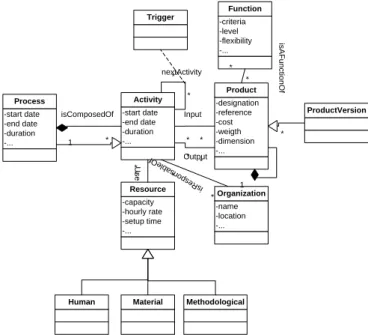
Based on the literature, we propose a simple model including the three views: Product, Process and Organisation. The product is linked to function and is an input and output of Activity. A combination of Activities from a Process, and they are launched by triggers. Resources are used by the activities, and are specialisable in human, material and methodological resources. The organisation is responsible for an activity. The class diagram is presented in Figure 1.
Combining the literature models is a first approach, but our goal is to obtain a model that will provide an improvement in the integration of PLM in mechanical SMEs. The models from the literature are mainly constructed with large companies and especially the design departments of these firms. The purpose of this paper is to obtain a model that will help the SMEs to implement PLM systems. These systems are shared with different departments, like design departments, but also manufacturing and purchasing departments. In the next section, a needs analysis of the different departments in SMEs is done to modify and improve the model extracted from the literature.
-designation -reference -cost -weigth -dimension -... Product -start date -end date -duration -... Activity * * Trigger -criteria -level -flexibility -... Function * * -capacity -hourly rate -setup time -... Resource * * -name -location -... Organization * * * * * * -start date -end date -duration -... Process 1 *
Human Material Methodological
isComposedOf Input Output U s e isR es po ns ab le Of nextActivity is A F u n c tio n O f ProductVersion 1 *
Figure 1: Model created from the literature review. 3 FUNCTIONAL REQUIREMENTS
To get the functional requirements of mechanical SMEs in terms of PLM, the proposition is an inductive approach. The modeller is immerged in different SMEs to understand their processes, the information flows, and the communication in the company and outside the company. The functional requirements are based on immersions done in representative SMEs [14]. The needs analysis is done by interviews and document analysis of the experts, by modelling their needs and by validations with the experts. To choose SMEs representatives from the mechanical field, a typology of those companies is proposed in [15]. The typology identifies three kinds of mechanical SMEs, the assembly manufacturers, the component manufacturers and the elementary part manufacturers. According with this typology, the three companies in our study are respectively a special machines manufacturer, a sailboat rigging manufacturer, and a crankshaft manufacturer. In each company, the design department, the manufacturing department and the procurement department were studied.
3.1 Design
The design department designs the product sold by the company. The design departments that were considered by our study were the one of a special machine producer and the one of a sailboat rigging manufacturer. The special machine design department already has a PDM system but needs improvements. The sailboat rigging design department does not have any information management system. The captured requirements are
CIRP Design Conference 2011 Product version
The versioning of a product allows the change of the product to be followed. The modified model includes a
ProductVersion class, specialisation of the Product class.
The different versions are linked by nextVersion associations. To be able to know the state of a version (in change, validated, obsolete, etc.), a state attribute is added to the other attribute of the ProductVersion class.
Product documentation
The documents associated with a product are many and varied. They can be CAD files, textual specifications, concept drawings, etc. A Document class is added and linked to the Product class.
Internal and external product
The policy, the right access, and the management of the product are different if the product is a finished product sold by the enterprise, an internal product managed by the company or a product bought from a supplier. The attributes of those products are also different. The modified model proposes to specialise Product in
FinishedProduct, Component and RawMaterial. Notice
that this view is a system view. The raw material could be a sub-system, if the sub-system is made by a supplier and the finished product could be an elementary part if the company sells elementary parts.
Design Bill of Material (BoM)
The BoM is an essential document for the design department, especially when designing complex systems. The solution proposed in the model is to link the Product class with itself. So the product is composed of other products (that can be components or raw materials).
Optional product
Optional components are components that are not obligatory in the construction of a product. A component could be optional in one product and obligatory in another. To distinguish the optional part from the core part of a product, the model adds a class to the product link that describes if the composition product-component is optional or not.
Alternative product
An alternative product is a component that could replace another component in a product. The alternative product does not change the product function, as defined in [16]. A ProductAlternative class is added to the model, linked to the Product class as alternative and context. The context link describes the assembly in which the alternative is validated whereas the alternative link describes the two interchangeable products.
Material
The material of a product is needed by the elementary parts manufacturer. To know the material of a product, a
Material class is added and linked to the Product class.
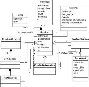
From the design department point of view, all of the necessary changes of the model presented in Figure 1 are related to the Product class. Figure 2 summarizes the modifications made.
3.2 Manufacturing
The manufacturing department prepares the process planning of the products sent by the design department or by a customer. The manufacturing departments were a sailboat rigging manufacturers and a crankshaft manufacturer. Both do not have a dedicated system for information management. The captured requirements are the following:
Operation version
The manufacturing department has different standard operations that evolve with the time. A versioning of operations allows them to follow the different modifications of an operation. In the model, the operation is a sub-class of Activity. An ActivityVersion class is added to the model. The different versions are linked by
nextVersion associations and a state attribute is added to
the ActivityVersion class like in the ProductVersion class.
Operation documentation
Those operations are documented by different files, like CAM file. So the Document class is also linked to the
Activity class. -reference -designation -cost -weigth -dimension -... Product ProductAlternative -reference -title -type of file -open with -size -... Document ProductVersion 1..* -c o n te x t * * -is A n A lte rn a tiv e O f * ** 0..1 -isComposedOf * 1 -nextVersion 1 -optional -type Link -reference -designation -criteria -level -flexibility -... Function * * -reference -designation -density -coefficient of expansion -melting temperature -... Material * * RawMaterial Component 1 * 1* FinishedProduct
Figure 2: Product class diagram.
Optional operation
On the standard process planning, some operations are not obligatory. Adding an optional attribute to the Link association of Activity class allows obtaining an optional operation in a process planning.
Machine capable to do an operation
A standard operation has a machine dedicated to this operation in the workshop. But another machine could be able to do this operation if the standard machine is overloaded. So a ResourceAlternative class is added to the model, linked to the machine that it can replace and to the operation (with a context association).
Manufacturing BoM
The BoM is not the same in the design department as in the manufacturing department. The components are not grouped in sub-systems in the same way. To allow that difference in the model, a type attribute is added to the association class of the product. This attribute is design, manufacturing… and allows the retrieval of the decomposition of a product specific to a department view. The Figure 3 shows the modifications on activity and resource models.
3.3 Procurement
The procurement department selects the suppliers and orders the products needed by manufacturing. It also selects the suppliers for outsourcing and external operations, like surface treatment for example, or rentals of specific resources. The procurement departments were the crankshaft manufacturer and the special machine manufacturer. In both cases, no information system is installed. The captured requirements are:
Supplier of a product
The supplier of the bought products must be identified. So the Organisation class is linked to the RawMaterial class.
Alternative supplier
They also need to know the other suppliers capable of supplying a product or an alternative product. An
OrganisationAlternative class is added to the model. It is
linked to an organisation in the context of the supplied product. -reference -designation -start date -end date -duration -... Activity ActivityAlternative -reference -title -type of file -open with -size -... Document ActivityVersion 1..* * * * * * 0..1 * 1 -nextVersion 1 -optional Link -nextActivity* * -reference -designation -type of trigger Trigger -reference -designation -capacity -hourly rate -setup time -... Resource ResourceAlternative 1..* -c o n te x t * * *
Human Material Methodological
* * is A n A lt e rn a ti v e O f is A n A lt e rn a ti v e O f c o n te x t isComposedOf
Figure 3: Activity class diagram.
Supplier of an operation
The procurement department does not manage only product procurement. It also manages outsourcing operations, like in the crankshaft company. In the model the Organisation is linked to the Activity.
Supplier of a resource
At last, the procurement department can also punctually rent resources, to respond to a customer order for example. The Organisation is also linked to the Resource in the model.
Figure 4 is the class diagram of the organisation. 3.4 Extended enterprise context
In an extended enterprise context, the companies have to exchange data to collaborate on all of the phases of the product lifecycle (from the early design phases with co-design to the disposal phase with the creation of a recycling plant, through the manufacturing phases with the supply chain). A finished product for a company becomes a raw material for another. Even a product for a company could become a process or a resource for another. For example, in the exchange between a special machine manufacturer and its customer, the product for the manufacturer (the special machine) becomes a resource when in the factory of the customer.
-reference -designation -cost -weigth -dimension -... Product -start date -end date -duration -... Activity -capacity -hourly rate -setup time -... Resource * * -name -location -... Organization * * * * * * * * * * input output belongTo u s e isR es po ns ab le Of OrganisationAlternative * * * * Supplier Customer
Figure 4: Organisation class diagram.
To facilitate the exchange of that information, applying a common structure to all of the enterprise objects is an interoperability improvement. The most important objects of the model, i.e. Product Activity Resource and Organisation, have similarities in their structure, with versioning, alternatives, documentation, etc. So in the model, the same structure is applied to all of those objects (see Figure 5).
-reference -designation EnterpriseObject EOAlternative -title -type of file -open with -size -... Document -state EOVersion * * * * * * 1 * 1 1 -optional -type Link con te x t is A n A lte rn a tiv e O f nextVersion isComposedOf is D o c u m e n te d B y -start date -end date -duration -... Activity -cost -weigth -dimension -... Product -capacity -hourly rate -setup time -... Resource -name -location -... Organization
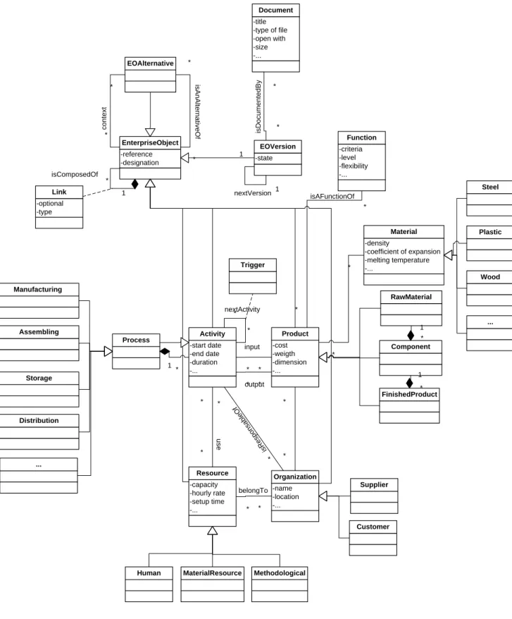
Figure 5: Enterprise Object class diagram. 3.5 Product/Process/Organisation model
Combining the different views presented in this section, the Product, Process, and Organisation are represented Figure 6.
4 IMPLEMENTATION OF THE MODEL
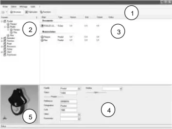
The proposed model is implemented in software based on a relational database. The software developed has client-server architecture. The client is developed in VB.Net and the server is based on MS SQL Server database. Figure 7 shows the interface of the software,
CIRP Design Conference 2011 -cost -weigth -dimension -... Product -start date -end date -duration -... Activity * * Trigger -criteria -level -flexibility -... Function RawMaterial * * -capacity -hourly rate -setup time -... Resource * * -name -location -... Organization * * * * * * * * * * Process Component 1 * 1 * Manufacturing Assembling 1 * Storage Distribution Supplier Customer
Human MaterialResource Methodological
input output belongTo u s e is R es po ns ab le O f nextActivity isAFunctionOf -reference -designation EnterpriseObject EOAlternative -title -type of file -open with -size -... Document -state EOVersion * * * * * * 1 * 1 1 -optional -type Link c o n te x t is A n A lte rn a tiv e O f nextVersion isComposedOf is D o c u m e n te d B y FinishedProduct * * -density -coefficient of expansion -melting temperature -... Material ... Steel Plastic Wood ...
Figure 6: Product/Process/Organisation model. a data card (4) and a viewer (5). The following
functionalities are implemented in the software:
Documentation
Each object is documented. A drag and drop from the desktop to the software interface adds the document to the database. A double click on the document opens it.
Versioning
Every object is versionnable. A right click on the object and the selection of “new version” creates a new version
of the object. It is also possible to retrieve the past versions.
Design/Manufacturing BoM
Different views are available. The design view and the manufacturing view give two different BoMs for the same product depending of the selected view.
Operation
The user can define optional operations, alternative operations and external operations (appearing in green)
(Figure 8). Then he loads the resources useful to each operation, dropping the input items, the work centres, the tools, etc.
Suppliers
The internal and external products are in the referential of the enterprise with different colours (yellow for the internal products and green for the external products). The external product can be taken directly from the supplier PLM systems. The different suppliers identified are present in a specific folder. A drag and drop from a component of the supplier to the software will import the product, all the attributes and the attached files.
The tool has been tested on three industrial scenarios to validate the proposed functionalities. The variety and representativeness of the chosen SMEs are ensured by the mechanical companies’ typology. The validation scenarios also include departments not taken into account by the study to construct the model, such as the procurement department of the sailboat rigging manufacturer or the manufacturing department of the special machine manufacturer. All of those points ensure a level of generality to the model.
Figure 7: Interface of the software.
Figure 8: Process planning of a crankshaft.
5 DISCUSSIONS AND PERSPECTIVES
This paper proposes a PLM model for design information management in the mechanical field. The method of construction is a two-step approach. The deductive phase is based on a literature review to create a reference model. The second one is an inductive step to modify the
model depending on the functional mechanical SMEs requirements.
The main result is a more complex enterprise object that enlarges the possibility of management on the activity, resource and organisation classes. This could be explained by the source of the literature PLM models and our specific study. PLM systems first aim to manage information from the product. So the design department is well represented in the specification of the data model. But other departments also use PLM systems, and their requirements are less taken into account. The fact that some of our case studies do not have a design department (only manufacturing and procurement services) underlines that imbalance between the design department and the others in the PLM specifications. In future work, we would like to include more steps of the lifecycle (maintenance, end of life, etc.) and more departments’ requirements in the PLM model. The SMEs that manage those phases should have a different point of view on a PLM that must be included in our model. 6 REFERENCES
[1] CIMdata Inc., 2003, Product Lifecycle Management “Empowering the future of business”
[2] Cetim, 2007, Étude sur les besoins en PLM, Document interne
[3] El Kadiri, S., Pernelle, P., Delattre, M., Bouras, A., 2009, Current situation of PLM systems in SME/SMI: Survey’s results and analysis, Proc. of 6th Int. Conf. PLM, 06-08 july 2009, Bath, UK [4] Sudarsan, R., Fenves, S.J., Sriram, R.D., Wang, F.,
2005, A product information modeling framework for product lifecycle management, Computer Aided Design,37 : 1399–1411
[5] Gamma, E., Helm, R., Jonhson, R., Vlissides, J., 1995, Design Patterns, Elements of reusable Object-Oriented Software, Addsison-Wesley [6] Gzara, L., 2000, Les patterns pour l’ingénierie des
systèmes d’information produit, Thèse de Doctorat, Institut National Polytechnique de Grenoble
[7] Chen, D., Vallespir, B., Doumeingts, G., 1997, GRAI integrated methodology and its mapping onto generic enterprise reference architecture and methodology, Computers in Industry, 33 : 387-394 [8] Labrousse, M., Bernard, A., 2008, FBS-PPRE, an
Enterprise Knowledge Lifecycle Model, Methods and Tools for Effective Knowledge Life-Cycle Management, Springer-Verlag, 285-307
[9] ISO 10303-214, 1998, Industrial Automation Systems and Integration - Product Data Representation and Exchange - Part 214: Application Protocol: Core Data for Automotive Mechanical Design Processes [10] ISO 10303-239, 2005, Industrial Automation
Systems and Integration - Product Data Representation and Exchange - Part 239: Application Protocol: Product Life Cycle Support [11] Noël, F., 2006, A dynamic multi-view product model
to share product behaviors among designers: how process model adds semantic to the behavior paradigm, Int. J. PLM, 1: 380-390
[12] Bennour, M., Crestani, D., 2005, Using competencies in performance estimation: From the activity to the process, Computer in Industry, 58 : 151-163
[13] Krause F.L., Kimura F., et al., 1993, Product Modeling, Annals of the CIRP, 42: 695-706
[14] Le Duigou, J., Bernard, A., Perry, N., Delplace, J.C., 1
2 3
5
CIRP Design Conference 2011
systems in mechanical SMEs Proceedings of 7th Int. Conf. PLM, 11-13 July 2010, Bremen, Germany [15] Le Duigou, J., Bernard, A., Perry, N., Delplace, J.C.,
2009, Global approach for product data management, application to ship equipment part families, CIRP J. MST, 1: 185-190
[16] BNAE – Bureau de Normalisation de l’Aéronautique et de l’Espace, 1991, Recommandation pour la Spécification de Management de Programme