This is an author-deposited version published in: http://oatao.univ-toulouse.fr/
Eprints ID: 4124
To cite this document: LIZY-DESTREZ Stéphanie, BOUCHIRED Steven. System
engineering approach applied to Galileo system. In: Complex Systems Design &
Management 2010 - CSDM 2010, 27-29 Oct 2010, Paris, France.
Any correspondence concerning this service should be sent to the repository
administrator:
[email protected]
System Engineering approach applied to Galileo System
Steven Bouchired, Thales Alenia Space, Toulouse, France
Stéphanie Lizy-Destrez, Institut Supérieur de l’Aéronautique et de l’Espace Toulouse, France
Introduction
Developing a localization system, with more precise per-formances than GPS that guarantees Europe autonomy is a complex challenge that ESA and a large number of European economical actors of space industry were decided to meet.
To design and manage such a huge system would have been impossible without applying System Engineering best practices, thanks to fundamental activities, multidisciplinary teams and dedicated tools.
This paper gives an overview of the System Engineering approach applied to design and develop Galileo, the European Satellite Radio-Navigation System.
Galileo system scope is so wide that we have decided to focus on some particular steps of the System Engineering processes that are: Requirements Engineering and Architec-ture. All along this paper, examples are given to illustrate the additional difficulties that have made Systems Engineering more and more complex.
Outline
This paper deals with:
1. Galileo system presentation 2. Requirement Engineering 3. Architectural design
Galileo System presentation
The Galileo System is the under deployment European Radio-Navigation Satellite System. The System will offer to end users all around the world a range of services including accurate positioning and timing, integrity guarantee for no-visibility landing, search and rescue. The system design is highly constrained by the demanding services performances: 4m (2-sigma) horizontal accuracy, 8m (2-sigma) vertical ac-curacy, 99.5% availability, ability to detect and inform the users about a hazardous misleading information in less than 6 seconds.
The Galileo Core System is composed of four main seg-ments that are: the Space Segment, the Launch Service Seg-ment, the Ground Segment and the User Segment.
The Space Segment
It provides the satellites, which will constitute the Galileo Constellation. The Galileo constellation will comprise thirty satellites in medium-Earth orbit (MEO) deployed in a Walker 27/3/1 plus three in-orbit spares. Each satellite will broadcast four ranging signals carrying clock synchronization, ephem-eris, integrity and other data.
The Launch Service Segment
It is in charge of deploying the satellites on their orbits (Launch, LEOP: Low and Early Orbit Phase, In-Orbit Tests).
The Ground Segment
It is composed of two parts the Ground Control Segment (GCS) and the Ground Mission Segment (GMS).
The Ground Control Segment
It is in charge of maintaining the satellites on their accurate orbits (5m 1-sigma radial orbit accuracy over 24 hours). The GCS is composed of two redundant control centers in Europe and of five TTC stations allowing S-Band TT&C communica-tion with the Galileo satellites all around the Earth.
The Ground Mission Segment
It is in charge of managing the Galileo Mission. This includes: • Generating mission data (satellite ephemeris, clock cor-rections, etc) on the basis of the continuous observation of the Galileo satellites. The update rate of the navigation data depends on the desired positioning accuracy.
• Dissemination of the mission data to the satellites with the constraint that each satellite shall be provided with re-cent enough data to allow meeting the service perform-ance.
• Disseminating data coming from external service provid-ers (Search-and-Rescue Return Link, Commercial Serv-ice, Regional Integrity).
The GMS is composed of two redundant control centers collocated with the GCS ones, of nine C-Band uplink stations (ULS) to upload the data to the satellites and of a network of around 40 sensor stations (GSS) in charge of monitoring the Satellite signals and sending the observables to the control centers.
The User Segment
It is not considered as part of the Galileo Core System, but its specification is under the responsibility of the Galileo Sys-tem Prime. Test User Receivers are developed to validate and qualify the System.
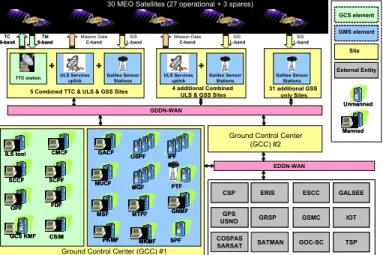
CSP
CSP ERISERIS ESCCESCC
Ground Control Center (GCC) #2
External Entity External Entity
Site Site
30 MEO Satellites (27 operational + 3 spares) 30 MEO Satellites (27 operational + 3 spares)
Ground Control Center (GCC) #1
TTC station GCS element CSIM CSIM FDF FDF
5 Combined TTC & ULS & GSS Sites
Unmanned Unmanned Manned Manned + + SIS
L-band Mission Data C-band L-bandSIS L-bandSIS
Mission Data C-band GMS element 31 additional GSS only Sites 4 additional Combined
ULS & GSS Sites
+ ULS Services uplink Galileo Sensor Stations ULS Services uplink Galileo Sensor Stations Galileo Sensor Stations MSF MSF SPF SPF PTF PTF PKMF PKMF PKMF MKMFMKMFMKMF TM S-band TC S-bandTC S-bandTM S-band SCCF SCCF CMCF CMCF OPF OPF ILS tool ILS tool SCPF SCPF GACF GACF MUCF MUCF GNMF GNMF GCS KMF GCS KMF GDDN-WAN GALSEE GALSEE GPS USNOGPS
USNO GRSPGRSP GSMCGSMC IOTIOT
SATMAN COSPAS
SARSAT GOC-SCGOC-SC TSPTSP
EDDN-WAN
MTPF MTPF OSPF
OSPF IPFIPF
MGF MGF
Figure 1: Galileo System description
The Galileo System is large and complex industrial system (as a technical and political point of view). Its main particu-larities lay in its technological innovations (accurate perform-ances are expected) and its European organization: a huge number of European industries are involved, increasing the interactions difficulties. Consequently, interfaces consolida-tion is one of the critical point.
Designing and managing the Development such a sprawl-ing System could not be possible without applysprawl-ing System Engineering good practices, methods and tools. The following figure sums up the global approach from needs elicitation to architecture.
Requirement Engineering
The main objectives of Requirements Engineering are: • To precisely determine the Stakeholders’ needs • To define the System boundaries
• To collect, refine and analyze the technical requirements • To write the System specification
About Galileo Lifecycle and Stakeholders
The complex industrial organization of the Galileo pro-gram as well as the long duration, has defined the stakeholders’ needs and of the system boundaries a particu-larly tough exercise. Reaching the decision to start the Galileo program has taken around a decade. Consequently the pro-gram has been characterized by its succession of short phases and by the high granularity of its contractual breakdown. The duration and short phases induce frequent human turnover. In such a context following a strict System Engineering frame-work is more necessary than ever but also more difficult than in any other type of projects.
For example, while focusing on early steps of the Galileo life-cycle1, the three main Galileo phases have been identi-fied: the “Preparatory” phases, the In-Orbit Validation (IOV) phase and the Full Operation Configuration (FOC) phase.
The “Preparatory” Phases (A, B, B1, B2, B2B, C0, C0 Rider) cover the period from 2000 to 2005. They correspond
1 Galileo program is an ESA program and is compliant with the ECSS. So the name of the different phases are coherent with European Standards.
to phases A and B of the project. The European Space Agency (ESA) is the main Stakeholder on behalf of the Euro-pean Commission (EC), while industrial companies perform feasibility and early design analyses in a succession of short contracts. The System PDR took place at the end of the B2B Phase, end of 2003.
The In-Orbit Validation Phase starting in 2006 seals a stronger commitment of Europe towards Galileo. It aims at consolidating the design of the full Galileo System and at de-ploying half of the Ground Segment and 4 satellites in order to validate key system concepts. During this phase, the
Sys-tem Prime and the SysSys-tem boundaries have changed.
In-deed ESA took over the System Prime responsibility in 2008. The System CDR of this phase started in September 2009, i.e. 6 years after the System PDR.
The Full Operation Configuration (FOC) phase will com-plement the system to reach full operability and service provi-sion by 2014. This phase is being negotiated at the time of writing this article.
System Prime Perimeter Evolution
The System CDR boundaries are summarized in the fol-lowing figure. The figure shows that the System Prime pe-rimeter has increased when ESA2 have taken over the re-sponsibility from the industrial consortium European Satellite Navigation Industries (ESNIS). These System boundaries are still increasing while entering the FOC phase with System Prime or Segments taking over the responsibility for some ex-ternal entities.
MRD
GSRD (sat.only services)
Sites IRD Ext IRD
ESNIS Perimeter
ESA Perimeter (for IOV CDR)
Segments (GMS, GCS, SSgt TUS) Sites Launchers, LEOP, IOT External Entities GOC GRSP RLSP TSP MEOLUT GSMC EC perimeter Other Services (Local Component, UMTS, ...) ...
Figure 2: System Prime Perimeter Evolution in
IOV Phase
Before ESA took over the System Prime role, the Stakeholders’ needs were considered to be described in an ESA document called GSRD (Galileo System Requirement Document). Industrial suppliers performed the System Design and the allocation to the Segments under strict supervision of ESA.
In the current context, the Stakeholders’ needs are de-scribed in the MRD (Mission Requirement Document) man-aged by the Galileo Supervision Authority (GSA) on behalf of the European Commission (EC). The role of the GSRD has de-facto evolved: it has become the System Technical Speci-fication Document. This evolution has been made without significantly changing the GSRD document. Indeed, changing
2 The Galileo System Engineering activity is now under the responsibility of ESA.
the GSRD requirements at such an advanced stage in the pro-ject is not an easy task in particular for traceability mainte-nance reasons.
The GSRD remains therefore a high-level specification document of around 340 requirements. The requirements derivation from the MRD is quite straightforward. The GSRD specifies:
• The Galileo Services performances and environment • The high level functions of the Space, Ground and User
segments
• Some general operational constraints mostly related to the constellation deployment and maintenance
• High level safety definitions
The GSRD is derived to the Segment requirements as shown in Figure 3. The number of segment requirements is around 400 to 500 requirements per segment REQ document (i.e. GMSREQ, GCSREQ and SSREQ). Both Interface Re-quirement Documents (IRD) and Interface Control Docu-ments (ICD) cover the interfaces with external entities like the Time Service Provider (TSP) or the SAR Return Link Service Provider (RLSP)..
As explained in the section on Architecture, this derivation is made through the Design Definition and Justification File (DDJF).
Figure 3: Requirement documentation
organization
The management of the large number of documents, re-quirements and interfaces was made using the DOORS tool. The further derivation of the Segment Requirements by the Segment contractors is then imported in the database in order to guarantee a full top-down traceability. The DOORS capa-bility to draw links between the documents objects (require-ments, data-flows, use cases) and to develop customized analysis scripts (DXL) has helped ensuring the consistency of design to a great extent.
Example of boundary evolution between system and segment
Galileo system is such a complex system, that it can be considered as a system of systems. Each sub-system can also be considered as a system. A System engineering approach has to be applied at sub-system level. In particular, the boundaries of each sub-system have to be clearly defined. But, boundaries evolutions have also occurred between sys-tem and segments. As an example, the responsibility for the Galileo Constellation has changed. In Phase B and during the
first year of the IOV Phase, the design of the Galileo constel-lation and the provision of the constelconstel-lation in orbit were fully allocated to the Space Segment (SSgt) contractor (see Figure 4). The only SSgt “external” interface at constellation level were those with External Satellite Control Center (ESCC) needed for LEOP and those needed to hand-over the satellites (once on their final orbit) to the GCS. In Mid-2007, the SSgt boundaries have been restricted to the satellites level. This of-fered the main advantages of having a better control on the deployment strategy. The constellation deployment strategy allows System trade-offs in terms of schedule and service per-formance with intermediate constellations geometry. From a pure System Engineering perspective the SSgt boundaries evolution implied that several interfaces which were SSgt in-ternal, such as the interface between the satellites and the launchers, have become “external” and therefore under the re-sponsibility of the System Prime. As mentioned above, the Launch Service has now become a Segment on its own.
Figure 4: Space Segment boundaries before
Mid-2007
Figure 5: Space Segment boundaries now
Architectural Design
After Requirements Engineering, the main step in System Engineering processes is to find the optimal solution that cor-responds to the Stakeholders’ needs. Finding such an optimal solution demands to design the best architecture at System level. Then System Engineers have to match the functional architecture and the organic architecture, so as to verify that the proposed solution complies with the expressed needs. This activity is named allocation.
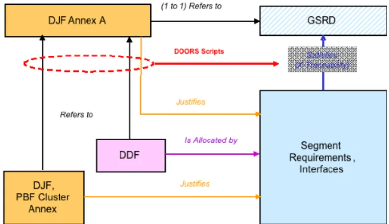
This section addresses the allocation of the system specifi-cation to the system segments. The requirement derivation addressed in the previous section is the result of the System Design Activity. Figure 6 shows that the derivation relation between the GSRD specification and the segment require-ments and interfaces is indeed generated through the Design Definition File (DDF) and Justification and Performance Budget File (resp. DJF and PBF). The DJF Annex A provides for each GSRD requirement a short summary of the DDF and DJF/PBF objects that contributes to meeting the system re-quirement. DOORS scripts exploit the DDJF traceability to automatically reconstruct the derivation links between the GSRD and Segment Requirements (X-Traceability).
Figure 6: Specification documentation
management
Functional architecture
The Functional Architecture constitutes the backbone of the Galileo System design. The Galileo System Functional Tree is an overlapping tree (i.e. branches can share leaves). The top of the tree is composed of the 15 main System Func-tional Chains:
SFC ID System Functional Chain
SFC1 Provide and Maintain the Galileo
Constella-tion
SFC2 Generate System Time and Geodetic
Refer-ence
SFC3 Maintain Overall System Synchronization
SFC4 Mission Services Provision
SFC5 Monitoring and Control
SFC6 Archiving
SFC7 Support Commercial Service (CS)
SFC8 Support Search And Rescue (SAR) Service
SFC9 Support External Regional Integrity Service
(ERIS) SFC11
(Cla)
Control Access to the Ground Infrastruc-tures
SFC12 (Cla)
Security Protection Of Satellite Monitoring And Control
SFC13 (Cla)
Security Protection For Mission Data SFC14
(Cla)
Security Protection Of Safety of Life (SoL) Service
SFC15 (Cla)
Security Protection Of Public Regulated Service (PRS)
The SFC makes use of segment functions. The Segment functions are related to input and output signals and are speci-fied in the Segment requirement documents.
DDF-I SFC DDF-I Segment Functions DDF-II Physical SignalDB (Data-Dictionary) Is Composed of Is Mapped on Link Interface Requirements, Interfaces (except Input Requirements) Is Allocated by Is Allocated by Is Allocated by Is Allocated by
Figure 7: Relations between the DDF Modules
and the Requirement and Interface Modules
The Figure 8 shows a DOORS to HTML export of a DDF section on the “Mission Planning” SFC (part of SFC5). In a format similar to a SYSML activity diagram, the DDF section describes how GCS and GMS functions interact to fulfill the SFC objective. Several System Interfaces contribute to the SFC, such as the GCS-GMS Interface. The diagram is also traced to the Segment Function descriptions and the involved logical signals. This allows to indirectly link the diagram to the Segment requirements and ICDs to which it is allocated.
Figure 8: DDF System Functional Chain Activity
Diagram
The segment functions are also organized in a tree group-ing the functions by segment. The tree is modeled in SDL as shown on Figure 9. This functional tree goes quite deep into the segments design.
As already mentioned, long “Preparatory” phase can result into boundary evolutions between System and Segments. The functional tree of the Galileo System (and therefore its re-quirement documents) still contains consequences of such boundaries evolutions. The previous section has given an ex-ample of a boundary transfer from Segment to System regard-ing the constellation and of the resultregard-ing major rework of segment requirement documents before the FOC phase. Transfers from System to Segments have also occurred. For instance, the Galileo Algorithms responsibility has been transferred from System to Segments around phase B2B. In such cases, the existing requirements are generally left to avoid felt unnecessary paper work. For instance, as the Gali-leo System has once had the responsibility for uplink
schedul-ing algorithms, a GMS function has been specified in GMSREQ. This function generates the up-link schedule that allows the GMS to format the navigation messages and the ULS to track the satellites (see GMSF3.5 on Figure 8). This function is specified by more than 20 requirements. Some of them can be considered as resulting from GMS internal per-formance allocation (e.g. “In case of tracking plan change, the ULS shall reacquire a satellite in a maximum of 12min”). The real system need is indeed that GMS uplink data to the satellites under certain constraints linked to the services per-formances.
The number of specified segment functions (e.g. 38 func-tion leaves in the GMS part of the system funcfunc-tional tree) is probably greater than what it could have effectively been. This generates unnecessary complexity at System level, which sometimes has to be managed by justified Requests for Deviations (RFD) from the Segments. It is difficult to escape paper work...
Figure 9: SDL Snapshot of the Functional Tree
Physic architecture (interfaces problematic)
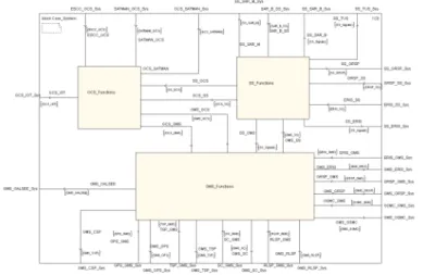
As explained above, the Galileo System is composed of 5 segments (N-1). The System Design Definition File part II (DDF2) describes the Galileo System Organic Architecture down to N-2 level (i.e. segments components) in order to match at least the level of details contained in the Interface documents.
The physical architecture consolidation is mainly about in-terface resolution. The two main tools that have been used to consolidate the interfaces have been:
- The Data-Dictionary resulting from the functional architecture
- The “Use Cases” Database
The Data-Dictionary
The SDL functional model allowed generating the System Data-Dictionary. The Data-Dictionary is the repository of all the data exchanged in the system. It can be seen as a tree of which the top level is composed by the logical signals derived from the functional analyses (e.g. DISS_MsgSubFr is the sig-nal generated by GMS and to be up linked to the satellites), and the leaves are the elementary data carried on these signals (e.g. clkT0 which is a satellite clock reference time coded on 14 bits carried over DISS_MsgSubFr but also other signals).
Practically the Data-Dictionary is an XML file originally exported from the SDL model. The file has then been com-plemented via a proprietary web-based tool to follow the in-terface consolidation process. The populated XML file is im-ported in DOORS in order to be traced to functions, requirements, ICDs and Use Cases.
The DOORS traceability allows checking that a parameter like almAf1 part of the satellite almanacs sent to the users to adjust their ranging measurements are properly encoded on the same number of bits (13) in all ICDs in which it appears (see
Figure 10
). Such an application of the Data-Dictionary traceability has proved particularly useful to check the coher-ency between the C-Band uplink ICD from GMS to the Satel-lites and L-Band downlink ICD from the satelSatel-lites to the GMS and Users.Figure 10: Example of Data-Dictionary
applica-tion
The amount of signals transiting over the Galileo System interfaces is in the order of several hundreds. However the data-dictionary contains much more signals (above 500) re-sulting from the SDL model segment internal function ex-changes. The data-dictionary is indirectly made applicable to the segments via the ICDs for inter-segment signals, and by the segment requirements for segment internal logical signals.
The “Use Cases” Database
The Galileo System “Use Cases” (UC) are sequences of interactions between the system components crossing at least one system Interface. Although the main UC´s have been de-fined early in the design phase based on the functional archi-tecture and Stakeholders need specification, the UC Database has been expanded all along the projects in two directions: (1) horizontally - the number of use cases has been increased to take into account special scenarios coming from the Opera-tion Needs or contingency cases identified by the RAMS analyses; (2) vertically – the use cases have been consolidated on the basis of the segments design at each segment CDR re-view in order to ensure and demonstrate overall system con-sistency.
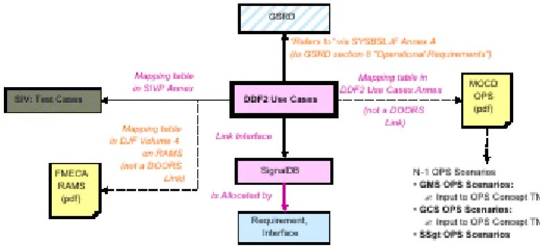
As shown in Figure 11, the Use Cases have played a cen-tral role for all the System Engineering activities. As a matter of fact, the UC´s are related to:
• The Operational Activities: The Operational Concept and GSRD Operational Requirements identified the main scenarios to be addressed. In addition, the Operation Engineering activities have continuously expressed
complementary needs while consolidating their
Operational Procedures. The Use Cases have been the tool to ensure the Design Operability.
• The RAMS Analyses: Through the Fault and Hazard Analyses (FHA) and Failure Mode Effects and Criticality Analyses (FMECA), the RAMS Activity identifies fault conditions to which the system must be resilient. The Use
Cases contingency scenarios allowed demonstrating the sequence of events allowing maintaining or returning the System in a safe and operational state.
• The Functions and Signals: The Use Cases Database is traced to the System Interfaces documents in order to allow ICD coherency with the Design.
• The System Integration and Verification Test Cases: The Use Cases Database has been used as a starting point for System Test Cases Definition.
Figure 11: Relation between the Use Cases and
the other System Documents
Conclusion
This article has provided a rapid overview of the
organization of the Galileo System Engineering
activities in the IOV Phase. It has illustrated the
importance of strictly following a solid System
Engineering process in a large scale program such
as Galileo. Indeed, hurdles are numerous: long
phases duration involving people turn-over, system
boundaries
evolutions,
complex
industrial
organization, and last but not least a real technical
challenge. The emphasis has been put on the
system boundaries evolutions along the project.
Despite those program difficulties, interesting
methods and tools (like Data-Dictionary for
domain analysis and System Functional chain for
Functional Architecture) were set-up for Galileo
and could be spread out to be reuse on other space
complex System programs.
Furthermore, as the verification and validation
activities are still on going, during this article
writing, no mature lesson learned can be at the
moment concluded. A further analysis must be
interesting, to complete the present one so as that
the whole V cycle will have been analyzed. This
shall lead to instructive conclusions on the
application of System Engineering methods on
such a real complex system
Acronyms list
Acronyms Definition
CDR Critical Design
Review
CMCF Central
Monitor-ing and Control Fa-cility CS Commercial Service CSIM Constellation SIMulator DDJF Design Definition
and Justification File
DDF Design Definition
File
EC European
Com-mission
ECSS European
Coop-eration on Space Standardization
ERIS External
Re-gional. Integrity
Systems
ESA European Space
Agency
ESCC External Satellite
Control Center
ESNIS European
Satel-lite Navigation In-dustries
FDF Flight Dynamics
Facility
FMECA Failure Mode,
Ef-fects, and Criticality Analysis
FHA Fault and Hazard
Analyses
FOC Full Operation
Configuration
GACF Ground Assets
Control Facility Acronyms Definition GCC Ground Control Center GCS Ground Control Segment GCS KMF GCS Key Man-agement Facility
GDDN Galileo Data
De-livery Network GMS Ground Mission Segment GNMF Galileo Network Monitoring Facility GPS Global Position-ing System
GOC Galileo Operating
Company
GRSP Geodetic
Refer-ence Service Pro-vider
GSA Galileo
Supervi-sion Authority GSMC Galileo Security Monitoring Center GSRD Galileo System Requirement Docu-ment GSS Galileo Sensor Station
ICD Interface Control
Document
ILS Integrated
Logis-tics Support
IRD Interface
Re-quirement
Docu-ment
IOT In Orbit Test
IOV In-Orbit
Valida-tion
IPF Integrity
8
Acronyms Definition
IVVQ Integration,
Veri-fication, Validation, Qualification
LEOP Launch and Early
Orbit Phase
MEO Medium Earth
Orbit MGF Message Genera-tion Facility MKMF Mission Key Management Facil-ity MRD Mission Re-quirement Docu-ment MSF Mission Support Facility MTPF Maintenance and Training Platform
MUCF Monitoring and
Uplink Control Fa-cility
OPF Operation
Prepa-ration Facility
OSPF Orbit
Synchroni-zation Processing
Facility
PDR Preliminary
De-sign Review
PKMF Public Regulated
Service Key Man-agement Facility
PTF Precise Timing
Facility
RAMS Risk Analysis
Management
Sys-tem
RLSP Return Link
Service Provider
SAR Search And
Res-cue Acronyms Definition SATMAN SATellite MANufacturer SCCF Satellite Central Control Facility SCPF Spacecraft Con-stellation Planning Facility SFC System Func-tional Chain
SIS Signal In Space
SoL System of Life
SSgt Space Segment TC TeleCommand TM TeleMetry TSP Time Service Provider TTC Telemetry,
Tracking & Control
ULS UpLink Station
UMTS Universal Mobile
Telecommunications System
USNO US Naval