canine model with non-invasive vascular elastography
par Elie Salloum
Institut de Génie Biomédical Faculté de Médecine
Mémoire présenté à la Faculté de médecine en vue de l’obtention du grade de Maîtrise
en Génie Biomédical (option recherche)
Novembre, 2014
Ce mémoire intitulé :
Abdominal aortic aneurysm follow-up after endovascular repair in a canine model with non-invasive vascular elastography
Présenté par: Elie Salloum
a été évalué par un jury composé des personnes suivantes :
Matthias Friedrich, président-rapporteur Gilles Soulez, directeur de recherche
Guy Cloutier, co-directeur
Le traitement chirurgical des anévrismes de l'aorte abdominale est de plus en plus remplacé par la réparation endovasculaire de l’anévrisme (« endovascular aneurysm repair », EVAR) en utilisant des endoprothèses (« stent-grafts », SGs). Cependant, l'efficacité de cette approche moins invasive est compromise par l'incidence de l'écoulement persistant dans l'anévrisme, appelé endofuites menant à une rupture d'anévrisme si elle n'est pas détectée. Par conséquent, une surveillance de longue durée par tomodensitométrie sur une base annuelle est nécessaire ce qui augmente le coût de la procédure EVAR, exposant le patient à un rayonnement ionisants et un agent de contraste néphrotoxique.
Le mécanisme de rupture d'anévrisme secondaire à l'endofuite est lié à une pression du sac de l'anévrisme proche de la pression systémique. Il existe une relation entre la contraction ou l'expansion du sac et la pressurisation du sac. La pressurisation résiduelle de l'anévrisme aortique abdominale va induire une pulsation et une circulation sanguine à l'intérieur du sac empêchant ainsi la thrombose du sac et la guérison de l'anévrisme.
L'élastographie vasculaire non-invasive (« non-invasive vascular elastography », NIVE) utilisant le « Lagrangian Speckle Model Estimator » (LSME) peut devenir une technique d'imagerie complémentaire pour le suivi des anévrismes après réparation endovasculaire. NIVE a la capacité de fournir des informations importantes sur l'organisation d'un thrombus dans le sac de l'anévrisme et sur la détection des endofuites.
une étude NIVE précédente. Une limitation de cette étude était l'absence d'examen tomodensitométrique comme étalon-or pour le diagnostic d'endofuites. Nous avons cherché à appliquer et optimiser la technique NIVE pour le suivi des anévrismes de l'aorte abdominale (AAA) après EVAR avec endoprothèse dans un modèle canin dans le but de détecter et caractériser les endofuites et l'organisation du thrombus.
Des SGs ont été implantés dans un groupe de 18 chiens avec un anévrisme créé dans l'aorte abdominale. Des endofuites de type I ont été créés dans 4 anévrismes, de type II dans 13 anévrismes tandis qu’un anévrisme n’avait aucune endofuite. L'échographie Doppler (« Doppler ultrasound », DUS) et les examens NIVE ont été réalisés avant puis à 1 semaine, 1 mois, 3 mois et 6 mois après l’EVAR. Une angiographie, une tomodensitométrie et des coupes macroscopiques ont été réalisées au moment du sacrifice. Les valeurs de contrainte ont été calculées en utilisant l`algorithme LSME. Les régions d'endofuite, de thrombus frais (non organisé) et de thrombus solide (organisé) ont été identifiées et segmentées en comparant les résultats de la tomodensitométrie et de l’étude macroscopique. Les valeurs de contrainte dans les zones avec endofuite, thrombus frais et organisé ont été comparées.
Les valeurs de contrainte étaient significativement différentes entre les zones d'endofuites, les zones de thrombus frais ou organisé et entre les zones de thrombus frais et organisé. Toutes les endofuites ont été clairement caractérisées par les examens d'élastographie. Aucune corrélation n'a été trouvée entre les valeurs de
taille de l'anévrisme.
Mots-clés : Aorte, anévrisme de l’aorte abdominal, réparation endovasculaire de l’anévrisme, élastographie non-invasive vasculaire, ultrasonographie, tomodensitométrie, endofuite, thrombus.
Surgical treatment of abdominal aortic aneurysms is increasingly being replaced by EVAR using SGs. However, the efficacy of this less invasive approach is jeopardized by the incidence of persistent flow within the aneurysm, called endoleaks leading to aneurysm rupture if not properly detected. Hence, a life-long surveillance by computed tomography (CT) angiography on an annual basis is increasing the cost of EVAR, exposing the patient to ionizing radiation and nephrotoxic contrast agent.
The mechanism of aneurysm rupture secondary to endoleak is related to a pressurization of the aneurysm sac close to the systemic pressure. There is a relation between sac shrinkage or expansion and sac pressurization. The residual pressurization of AAA will induce sac pulsatility and blood circulation in the sac thus preventing sac thrombosis and aneurysm healing.
NIVE using the LSME may become a complementary follow-up imaging technique for EVAR. NIVE has the capability of providing important information on the thrombus organization within the aneurysm sac and on the detection of endoleaks.
The characterization of the thrombus organization was not possible in a previous NIVE study. A limitation was the absence of CT examinations as gold standard for endoleak diagnosis. In the current study, we aimed to apply and
and characterize thrombus organization.
SGs were implanted in a group of 18 dogs with an aneurysm created in the abdominal aorta. Type I endoleak was created in 4 aneurysms, type II in 13 aneurysms and no endoleak in 1 aneurysm. DUS and NIVE examinations were performed at baseline, 1-week, 1-month, 3-month and 6-month follow-up after EVAR. Angiography, CT-scan and macroscopic tissue slides were performed at sacrifice. Strain values were computed using the LSME. Areas of endoleak, solid thrombus (organized) and fresh thrombus (non-organized) were identified and segmented by comparing the results of CT scan and macroscopic tissue slides. Strain values in areas with endoleak, organized and fresh thrombi were compared.
Strain values were significantly different between endoleak and organized or fresh thrombus areas and between organized and fresh thrombus areas. All endoleaks were clearly characterized on elastography examinations. No correlation was found between strain values and type of endoleak, sac pressure, endoleak size and aneurysm size.
Keywords : Aorta, abdominal aortic aneurysm, endovascular repair, non-invasive vascular elastography, ultrasound, computed tomography, endoleak, thrombus.
RÉSUMÉ ………..…. i
ABSTRACT ……….……….… iv
TABLE OF CONTENTS ……….... vi
LIST OF TABLES ………...… ix
LIST OF FIGURES ………... ix
LIST OF ABBREVIATIONS ………. xiv
DEDICATION ………. xv
AKNOWLEDGEMENTS ………...… xvi
Section I: Clinical Perspectives of Abdominal Aortic Aneurysm ………... 1
Chapter I: Abdominal Aortic Aneurysm, a chronic degenerative disorder ………..… 3
1. Abdominal Aortic Aneurysm, a chronic degenerative disorder ………... 4
1.1. Background ……….……. 4
1.2. Anatomy and Physiology ………... 5
1.2.1. Abdominal Aorta ……….….. 10
1.2.2. Abdominal arteries and pelvic arteries ……….……. 12
1.3. Pathophysiology of abdominal Aortic Aneurysm ………... 14
1.3.1. Elastin and Collagen ……….……. 15
1.3.1.1. Elastin ……….…… 15
1.3.1.2. Collagen ……….……. 17
1.3.2. Smoking ……….…… 17
1.3.3. Other factors increasing the pressure on the aortic wall ……….... 18
1.4. Epidemiology ... 19
1.4.1. Age and sex ……….... 19
1.5. Abdominal Aortic Aneury………... 21
1.5.1. Rupture ………... 21
1.5.2. Imaging techniques ……….... 22
1.5.2.1. Surveillance ……… 24
1.5.2.2 Screening and diagnosis ……….. 25
1.5.3. Intervention ……….…………... 25
1.5.3.1. Open Surgical Repair ……….. 27
1.5.3.2. Endovascular aneurysm repair ……….…... 28
1.5.3.3. Comparison between Open Surgical Repair and EVAR ……….……... 30
Chapter II: Endoleak ………... 33
2. Endoleak ……….. 34
2.1. Endoleak Types ……….…... 34
2.2. Imaging detection techniques ……….….... 38
2.2.1. CT Scan ………... 38
2.2.2. Ultrasound ………... 41
2.2.3. Angiography ……….. 43
2.2.4. Magnetic Resonance Imaging ………... 45
Chapter III: Quasi-static elastography (QSE-LSME) ………... 49
3. Elastography ……….... 50
3.2. Quasi-static elastography ………....… 53
3.3. Lagrangian speckle model estimator (LSME) ……….... 54
Section II: Abdominal aortic aneurysm follow-up after endovascular repair in a canine model with non-invasive vascular elastography ……….... 60
Chapter IV: Abdominal aortic aneurysm follow-up after endovascular repair in a canine model with non-invasive vascular elastography ……….... 62
4. Aortic aneurysm in a canine model ………...….. 63
4.1. Abdominal aortic aneurysm follow-up after endovascular repair in a canine model with non- invasive vascular elastography ……… 65
4.1.1. Introduction to Manuscript ……… 65
4.1.2. Role of authors ………...………..…...… 66
4.1.3. Thesis format of submitted manuscript ………. 70
4.2. Manuscript submitted to Radiology ……….... 70
Abbreviated title page ... 71
Introduction ………...….. 76 Methods ………... 78 Results ………... 85 Discussion ………...… 87 Conclusion ………...…... 90 Tables ………... 92 Figure caption ………... 96 References ……….. 115
4.3. Further discussion and future perspectives ………... 118
4.3.1. Study methodology ………. 118
4.3.2. Limitations ……….. 122
4.3.3. Future work ………. 123
Table 4.1: NIVE strain parameters in segmented regions.
Note: Max/MinAxStrain = maximum and minimum axial strains; MaxCumAxStrain = maximum cumulated axial strain; Max/MinStrainRate = maximum and minimum strain rates; E = Endoleak; OT = Organized Thrombus; FT = Fresh Thrombus; * = Wilcoxon rank sum test.
Table 4.2: Comparison as a function of endoleak type (aneurysms with type I vs type II endoleak).
Comparison of strain values in endoleak, organized thrombus and fresh thrombus regions as a function of endoleak type (aneurysms with Type I vs type II endoleak). No statistical significant difference was found for any of the parameters.
Table 4.3: Aneurysm and endoleak size measurements.
Note: Type of endoleak according to the Society of Vacular Surgery Classification (0= no endoelak). (ref). The % of difference in aneurysm diameter is measured between sacrifice and 1 week after implantation of the SG on DUS. A (+) sign indicates that the diameter has increased whether a (-) sign indicates a shrinkage in the aneurysm diameter. The dog number 15 had no endoleak detected through CT scan, DUS and macroscopic tissue slides.
Figure 1.1: Cardio vascular system (CVS)
Figure 1.2: The three layers forming the arterial wall: The tunica intima, tunica media and tunica adventitia
Figure 1.3: The aorta is divided in 4 sections: The ascending aorta, the aortic arch, the descending aorta and the abdominal aorta
Figure 1.4: Posterior abdominal wall after removal of the peritoneum Figure 1.5: Abdominal arteries and pelvic arteries
Figure 1.6: Abdominal Aortic Aneurysm pathogenesis
Figure 1.7: The architecture of the healthy human artery showing the elastin and collagen fibrils Figure 1.8: Prevalence of AAA depending on age and sex from Sweden and Kansas City
Figure 1.9: A CT scan examination showing an AAA with a contained rupture Figure 1.10: Ultrasound gray scale mode of an AAA
Figure 1.11: CT scan identifying the AAA lumen, wall, calcification, thrombus Figure 1.12: Open surgical repair
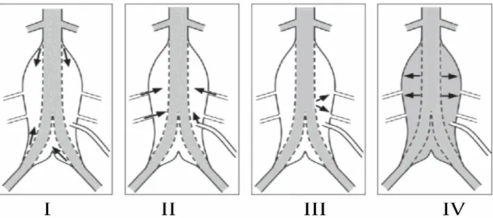
Figure 1.13: EVAR where a SG is placed inside the aneurysm without exposure of the abdominal aorta Figure 2.1: Visualization of the 4 types of endoleak. Type I: Blood flow coming from the proximal
distal neck; Type II: Collateral flow coming from the collateral arteries; Type III: A gap in the SG leading to a blood flow inside the aneurysm sac; Type IV: graft porosity
Figure 2.2: Axial CT scan image of an 80 years old female showing a type I endoleak
Figure 2.3: Doppler ultrasound acquisition showing a blood flow outside the SG and inside the aneurysm sac (endoleak)
Figure 2.4: Angiography acquisition of a 80 years old female showing a type I endoleak on the left side (indicated with a white arrow)
Figure 2.5: Contrast enhanced MRI image showing a type II endoleak (white arrow)
Figure 3.2: Three elastography imaging approaches: (a) Quasi-static elastography where the mechanical source is either from outside or inside the organ of interest (e.g., from inside in the case of the pulsation of an artery), (b) harmonic elastography, and (c) transient elastography
Figure 3.3: A stress/strain curve of a linear elastic material. Beyond a certain level of deformation, the material reaches an elastic limit and breaks
Figure 4.0: Representation of the AAA reconstruction
Figure 4.1: The macroscopic tissue slide is first analyzed to detect the presence of an endoleak through a defect/gap in the aneurysm sac. If the presence of the defect correlates with CT scan contrast enhancement in the same region, presence of an endoleak is confirmed. The rest of the tissue in the aneurysmal sac is characterized as organized or fresh thrombus according to its appearance on macroscopic cuts. Note: C+ means contrast on CT scanner.
Figure 4.2: Example of macroscopic tissue slide (a) with endoleak (1), fresh thrombus (2) and organized thrombus (3). Corresponding histology with Movat staining (b) and immunostaining of alpha smooth muscle actin (αSMA, in brown)) (c and d). The brown region corresponds to the dense fibrous connective tissues (organized thrombus). The blue region corresponds to the fresh thrombus (c and d) which confirms the areas of fresh thrombus (loose thrombus with black brown coloration and absence of fibrous organization) and organized thrombus (dense fibrous organization with a yellowish appearance) on the macroscopic tissue slides Figure 4.3a: LSME was applied to compute time varying strain curves for 3 or more consecutive cardiac
cycles. This figure shows the instantaneous axial strain curve on 90 frames (7 cycles). MaxAxStrain and MinAxStrain represent the mean value, over acquired cardiac cycles, of positive and negative peaks of the time varying instantaneous axial strain curve, respectively.
Figure 4.3b. A cumulated axial strain curve over the same 90 frames (7 cycles). MaxCumAxialStrain is the average, over acquired cardiac cycles, of maximum positive values of the cumulated axial strain curve, corresponding to peak dilatation.
before sacrifice and showing a large type I endoleak at the proximal neck. CT scan is used as a reference for endoleak segmentation and registration on elastogram.
Figure 4.4b. Transverse acquisition of Doppler Ultrasound at the same level than CT scan (Figure 4.4a). Figure 4.4c. A macroscopic tissue slide at the same level shown in figure 4.4a and 4.4b. The endoleak
area is well visible (dashed arrow). A small area of fresh thrombus seen as a soft black brown area is depicted (white arrow). The organized thrombus is seen at the upper portion (thin arrow with an oval head) of the macroscopic cut. These 3 regions of interest located on the macroscopic tissue slide are segmented and registered on the elastogram for computation of strain parameters.
Figure 4.4d: Cumulated axial strain elastogram of the entire aneurysm sac at the same level that Figure 4.4,a,b,c The region of accumulation of very high and low strain values on the middle left of the elastogram (white arrow) corresponds to the region of endoleak.
Figure 4.4e: Cumulated axial strain elastogram of the endoleak region of the same dog 1 at the same level segmented based on the CT scan and macroscopic results showed in figure 4.4a and 4.4c.
Figure 4.4f: Cumulated axial strain elastogram of the fresh thrombus region of the same dog 1 at the same level segmented based on the macroscopic results showed in figure 4.3c.
Figure 4.4g. Cumulated axial strain elastogram of the organized thrombus region of the same dog 1 at the same level segmented based on the macroscopic results showed in figure 4.3c.
Figure 4.5: Mean and SD Maximum Axial Strain values for the three regions of interest. A statistical significant difference was found when comparing the endoleak, organized and fresh thrombi.
Figure 4.6: No correlation has been found between the pressure measured inside the aneurysm sac and the maximum axial strain parameter results.
Figure 4.7: No correlation has been found between the aneurysm area measured on CT scan and the maximum axial strain parameter results.
maximum axial strain parameter results.
Figure 4.9: Quasi-static compression elastography examination of a breast carcinoma. The color indicates the relative stiffness (red to blue)
2D, two-dimensional 3D, three-dimensional
AAA, Abdominal aortic aneurysm CEUS, contrast-enhanced ultrasound
CHUM, centre hospitalier de l’Université de Montréal
CRCHUM, centre de recherche du centre hospitalier de l’Université de Montréal CT, computed tomography
CTA, computed tomography angiography CVS, cardio vascular system
DUS, Doppler ultrasound E, Young’s elastic modulus
EVE, endovascular ultrasound elastography EVAR, endovascular aneurysm repair IVUS, intravascular ultrasound
LBUM, Laboratory of biorheology and medical ultrasonics LCTI, clinical image processing Laboratory
LSME, lagrangian speckle model estimator MRI, magnetic resonance imaging
n, number (as in number of subjects or number in sample population) NIVE, non-invasive vascular elastography
QSE, quasi-static elastography r, Pearson correlation coefecient RF, radiofrequency
ROI, region of interest SG, stent graft
Gibran Khalil Gibran
I would like first of all to thank Dr. Gilles Soulez for offering me the chance to be part of his team and work on this stimulating project. His patience and his professional advices showed me the way through to finish my research with success. He didn’t stop encouraging me, believing in me and being concerned on the personal and academic levels. I will be thankful to him the rest of my life. I also would like to thank Dr. Guy Cloutier for accepting me in his lab, part of the quasi-static elastography team and guiding me with professional advices that will remain with me through my entire professional career.
Thank you to Dr. Marie-Hélène Roy-Cardinal, Jonathan Poré and Zhao Qin for their help in answering all my questions and optimizing the quality of my elastograms. Thank you to each member of the LBUM: Dr. Louise Allard, Boris Chayer, Dr. Zahra Kesha Mottamed, Dr. Shahrokh Shahriari, Emmanuel Montagnon, Daniel Posada, Dr. Damien Garcia, Abderrahmane Ouared and Julián Andrés
García Duitama for their support and everyday smile, they were a family to me the past 2 years. I would
also like to thank Andrée Cliche, Dr. Claude Kauffmann, Michel Gouin, Jocelyne Lavoie, Dr. Sophie Lerouge, Anthony Bertrand Grenier and the entire animal house team for their kindness, patience and help in obtaining the final results. It was really a pleasure working with all of you.
I am grateful for the CRCHUM and to the Biomedical Engineering Institute of the University of Montreal and for each association I have received a scholarship from.
A special acknowledgment for my parents who dedicated their life for my education, for raising me and leading me through each step till I was able to reach my dream. I know how difficult that job is in a third world country. Also a special acknowledgment for all the friends I met in Montreal who became my family, for their support and encouragement.
At the end I thank God for all the people he put on my road, all the happy and sad moments I experienced and for giving me the patience to perceive my dream till the end. Mostly for sending me the most wonderful person who has been my angel. A special acknowledgment to my wife.
Section I
CHAPTER I
Abdominal Aortic Aneurysm, a chronic degenerative
disorder
1. Abdominal Aortic Aneurysm (AAA), a chronic degenerative disorder
1.1 Background
The abnormal dilation involving the vascular wall three layers: the intima, the media and the adventitia defines an aneurysm. The word itself derives from the Greek word “aneurusma” that has the meaning of widening. A perivascular pulsatile hematoma secondary to a vessel injury is not limited by the three layers and is called false aneurysm [1]. Aneurysms can be designed as fusiform or “saccular” depending on whether the entire circumference of the aorta is affected or a part of it respectively [1]. The normal diameter of the abdominal aorta measures between 15 and 24 mm depending on the age, sex and bodyweight. It is considered an AAA when exceeding the 30 mm diameter and preventive treatment is needed when reaching 50 mm in diameter [2, 3].
This chapter will focus on understanding the clinical and pathological aspects of the abdominal aortic aneurysm. Other issues related to the AAA will be described and further explanation of the project will be presented.
1.2 Anatomy and Physiology
The arterial system is classified based on the specific vascular territories it supplies and it is divided in three classifications (figure 1.1):
- The large vessels as the aorta and iliac arteries characterized with an elasticity that helps in maintaining the diastolic blood pressure.
- The medium-sized vessels that distribute blood to capillary beds as visceral branches, brachial arteries, superficial femoral and muscular arteries.
- The small arterioles that play a role in blood pressure regulation, vascular tone modulation and oxygen and nutrients delivery to the different body tissues [4].
6
Tunica media
Medium-sized vein
Tunica
Tunica
media "{ff'f---Tunica
intima
The tunica intima, tunica media and tunica adventitia constitute the three layers of the arterial wall (figure 1.2):
- The internal layer of the artery is the tunica intima consisting of a single layer of mesenchymal endothelial cells with basement membrane and internal elastic lamina. The media and intima are attached with supportive connective tissues. Thin in healthy individuals, it becomes stiffer and thicker with age, due to pathological changes. This leads to significant alterations in the mechanical properties of the arterial wall.
- The tunica media, the middle layer of the artery, is considered the thickest layer of the arterial wall. It plays a role in modulating the arterial vascular tone and blood pressure because of the actin and myocin filaments contained in the smooth muscle cells. The media is separated from the intima and adventitia by the internal elastic lamina and the external elastic lamina, respectively. Mechanically, the media is considered to be the most important layer in a healthy artery.
- The tunica adventitia, the outer layer of the artery, consists mainly of cells that produce collagen and elastin such as fibroblasts and fibrocytes, and fibrous tissues. It is surrounded by loose connective tissues, lymphatics and the vasa vasorum, which is its own nutrient
supply. Under high blood pressure, when the collagen fibers reach their straightened lengths, the adventitia becomes stiffer to prevent the rupture and the overstretching of the artery [4, 6].
Figure 1.2 The three layers forming the arterial wall: The tunica intima, tunica media and tunica adventitia [7]
The aorta is the largest artery of the human body starting at the left ventricle of the heart (figure 1.3):
- The first part rising up from the heart is called the ascending aorta; it supplies the heart with blood through the coronary arteries.
- It curves than through the aortic arch and supplies the head, arm and neck.
- The part going through the chest is called the descending aorta. It supplies blood to the chest and some ribs.
- The abdominal aorta starts at the diaphragm and bifurcates into the paired common iliac arteries [8].
Figure 1.3 The aorta is divided in 4 sections: The ascending aorta, the aortic arch, the descending aorta and the abdominal aorta [9]
1.2.1 Abdominal Aorta
The abdominal aorta starts when the descending aorta passes over the twelfth thoracic vertebra (lower portion) and under the aortic hiatus of the diaphragm. It ends by bifurcating into the right and left common iliac arteries on top of the lower third of the fourth lumbar vertebra and left to the midline. The bifurcation is located using the intercrestal line, which locates an abdomen transverse plane at the fourth lumbar level. The lower portion of the abdominal aorta is located behind the peritoneum of the posterior abdominal wall (figure 1.4). To the left and right of the abdominal aorta is situated the sigmoid mesocolon and the oblique line of origin of the mesentery of the small intestine, respectively. The aorta is embedded, behind the posterior body wall peritoneum, in the extra peritoneal areolar connective tissue. Under and to the left and right of the common iliac arteries stands the left and right common iliac veins, respectively. Behind them the sympathetic trunks go down into the pelvis [10, 11].
1.2.2 Abdominal arteries and pelvic arteries
The collateral arteries arising from the abdominal aorta divide to sub- branches in order to supply the abdomen and the pelvis (figure 1.5). These branches can be divided into five groups depending on their function:
1- The first group supplies the kidneys, diaphragm, adrenal glands, posterior abdominal wall, gonads and spinal cord. It includes the right and left renal arteries, the right and left inferior phrenic arteries, the right and left middle adrenal arteries, the right and left lumbar arteries, the right and left testicular arteries and the median sacral artery.
2- The second group made of the celiac trunk, that gives rise to the left gastric artery, the splenic artery and the common hepatic artery, supplies the liver, gallbladder, pancreas, spleen, stomach and duodenum.
3- The third group made of the superior mesenteric artery supplies the small intestine and part of the large intestine.
4- The fourth group made of the inferior mesenteric artery supplies the other part of the large intestine.
5- The fifth group supplies the pelvis through an indirect trunk arising from the common iliac artery: the internal iliac artery [13].
1.3 Pathophysiology of Abdominal Aortic Aneurysm
The arterial blood pressure imposed on the aorta is high and remains for a life time. This is why any weakness in the wall can lead to dilatation and the formation of an aneurysm, which can promote rupture and sudden death [15].
Figure 1.6 Abdominal Aortic Aneurysm pathogenesis [15]
1.3.1 Elastin and Collagen
Many factors involved in wall weakening and load increasing interact together leading to an aneurysm formation. Figure 1.6 represents well the sequence and reasons behind the formation of abdominal aortic aneurysms. Elastin and collagen are considered to be the aortic wall’s most important
proteins that form fibers that help make up connective tissues in the body. The elastin is responsible of the elastic property that allows it to stretch during cardiac contraction and relax along with the cardiac relaxation. On the other hand, the collagen is the opposite of the elastin and it is considered to be 20 times stronger. In case of an extension that exceeds its original length, damage may occur. We can say that collagen acts as a safety net when the elastin exceeds its stretching limit [16-22].
1.3.1.1 Elastin
One of the reasons that aneurysms occur more frequently in the abdominal is that the elastin is less present than other parts of the aorta such as the thoracic aorta. The elastin content is lower in the aortic wall of patients with aneurysms when compared to normal abdominal aorta affecting mechanical properties that depend on the concentration of the elastin [23-28].
Figure 1.7 The architecture of the healthy human artery showing the elastin and collagen fibrils [29]
1.3.1.2 Collagen
Different from elastin, collagen is synthesized throughout life. The most important deficiency linked to aneurysms is collagen type III deficiency. It has been associated with intra-cerebral aneurysms and Ehlers- Danlos syndrome type IV, the latter including abdominal aortic aneurysms as one of its manifestations. An increase in collagen has been reported in abdominal aortic aneurysm walls. In order for the rupture to occur, the destruction of the medial collagen is required through enzymes [19, 20, 30- 33].
1.3.2 Smoking
Abdominal aortic aneurysm has been associated to smoking since the 1960s [34]. A large study conducted in 1991 has found no relation between the number of cigarettes smoked and the risk of AAA. It has also been shown that hand-rolled cigarette smokers have higher risk than others [35]. In his study, Teun et al. has shown in 1999 that the effect of smoking on the risk of aneurysms is higher than its risk on coronary disease and peripheral vascular disease. Smokers are 7 times more likely to have an AAA than non-smokers. As for the ex-smokers, they are 3 times more likely to
develop an AAA when compared to non-smokers. Even when people quit smoking, the risk remains [35, 36].
1.3.3 Other factors increasing the pressure on the aortic wall
Many factors are involved in increasing the load on the aortic wall, making its dilatation, when added to other factors, easier. Hypertension is considered the most important. It increases the prevalence and the risk of rupture of an aortic wall [37-39]. It remains unclear whether arterial hypertension by itself is a major cause of AAA or whether it has to be combined with a pre-existing weakness of the aortic wall [40, 41].
Another important factor is the location of the abdominal aorta. It is the biggest artery in the body connected directly to the heart, which is the location with highest pressure. So the pulse pressure is high as the pulse wave passes through the abdominal aorta to reach the iliac bifurcation [42]. Genetic factors may also play a role with inherited defects affecting the function of elastin or collagen [43-48]. Inflammation may also cause the destruction and weakening of the aortic media. Inflammatory aneurysms are found in 4 to 10 per cent of the cases undergoing surgical treatment [49- 51].
1.4 Epidemiology
AAA is considered as the 13th leading cause of death in the United States of America and responsible of the death of 0.8 per cent of the entire deaths in the country [52].
1.4.1 Age and Sex
The prevalence of AAA in men is higher than in women [53]: In England and Wales 1.36 per cent of men versus 0.45 of women die due to an abdominal aortic aneurysm [54]. In 2005, 4907 men versus 1991 women died in England because of AAA [55]. Also AAA is found more frequently at old people versus young people [53, 56-59]. As shown in figure 1.8, the prevalence increases quickly from 1 per cent when reaching the age of 60 years till it reaches its maximum at the age of 80 years. The mortality rate starts between the age of 40 and 70 years [58].
Figure 1.8 Prevalence of AAA depending on age and sex from Sweden and Kansas City [53, 57, 60]
1.5 Abdominal Aortic Aneurysm 1.5.1 Rupture
The size of the aneurysm and the growth rate are considered to be the most important factors for the assessment of the aneurysm rupture risk [61- 64]. When the aortic diameter exceeds 30 mm, it is defined as an abdominal aortic aneurysm [65]. Most of the AAA ruptures occur before the patient reaches the surgical room [66]. This is why AAA has a high mortality rate of 65 to 85% of the patients [67]. When the diameter exceeds 5.5 cm, the patient should normally undergo surgery. This is why it hasn’t been found a lot of data concerning the risk rupture of large abdominal aortic aneurysms. It has been shown that the rupture rate of AAAs with a diameter between 4 and 5.5 cm is between 0.7 and 1% / year [68]. When comparing the rupture rate between women and men, it has been found that women have a higher rupture rate for small AAAs and equivalent rupture rate for large AAAs (≥ 5.5 cm) [69, 70]. AAA rupture risk increases with larger diameters. A prospective cohort study performed in 47 Veterans Affairs medical centers on 198 patients revealed a 1-year incidence of rupture of 9.4% for AAA at 5.5 to 5.9 cm, 10.2% for AAA of 6.0 to 6.9 cm (19.1% for the subgroup of 6.5-6.9 cm), and 32.5% for AAA of 7.0 cm or more [71]. On the other hand many studies have shown that size is not the only significant determinant of
rupture. Expansion and rupture may occur regardless of the diameter of the AAA [61, 72].
1.5.2 Imaging techniques for assessing AAAs
Ultrasound is the first line examination to detect an aneurysm and assess its maximal diameter. Computed tomography is a second line examination providing reproducible measurements of maximal diameters and information on AAA extension. The choice between these two techniques depends on the indication and the accessibility of the region for ultrasound, which is often impaired in the abdomen. Obesity is a frequent factor making an ultrasound assessment of the abdominal aorta difficult [1].
1.5.2.1 Surveillance
Once diagnosed, AAA of less than 55 mm in men or 50 mm in women are typically monitored every 6 months by ultrasound for changes in its maximal diameter [74, 75].
1.5.2.2 Screening and diagnosis
AAA, if not discovered as an incidental findings in an abdominal scan for other indications often presents itself for the first time when it ruptures and thus have a high mortality [1]. In several countries including UK, USA and Canada, screening programs have been established to reduce AAA related mortality [77, 78].
1.5.3 Intervention
A CT scan is usually the technique of choice to identify patients with an indication for a surgical intervention (figure 1.9), based on diameters of 55 mm (men) or 50 mm (women). CT scan helps in determining the exact size of the aneurysm, localizing the aortic branches, identifying any calcification or inflammation and determine whether the patient can be eligible for open or endovascular repair (figure 1.11).
1.5.3.1 Open surgical repair
The indication for open surgical repair is based on the physician assessment of the patient surgical risk. Many factors that can increase the risk of this intervention may eliminate this option such as previous history of cardiac atherosclerotic disease (myocardial infraction and angina pectoris), stroke, diabetes and age. During the surgical operation, the aneurysm is repaired by interposing a graft through an incision at the abdomen level (figure 1.12). The mortality rate for this procedure has been recently estimated to be 4.1% - 6% [2, 80].
1.5.3.2 Endovascular aneurysm repair
EVAR is less invasive and does not require any abdominal incision or exposure of the abdominal aorta. It involves the deployment of a stent graft (SG) inside the aneurysm to exclude the aneurysm sac from the blood circulation (figure 1.13) [82]. EVAR has been presented as an alternative to open surgical repair with a lower rate of post-operation mortality [2, 80]. The main limitation of EVAR is the durability of aneurysm exclusion and the occurrence of endoleaks (explained in Chapter 2). These limitations required long-term post placement surveillance (CT scan life-long follow up), diagnostic studies and possible secondary procedures, which increase the cost of EVAR by 50% [83-85].
Figure 1.13 EVAR where a SG is placed inside the aneurysm without exposure of the abdominal aorta [86].
1.5.3.3 Comparison between open surgical repair and EVAR
EVAR has been introduced mainly to replace open surgical repair for the patients at higher surgical risk due to age, body weight and cardiac condition. As mentioned above, the post-operative mortality rate is lower than the open surgical repair but when it comes to the long term mortality rate, it has been found to be the same especially because of the occurrence of delayed rupture associated with endoleaks and the high rate of deaths non related to aneurysm disease [87].
When comparing EVAR with open surgical repair, we find less surgical complications for EVAR and higher rate of long term success for surgery [2, 88-95]. The cost of an EVAR is about 20,000$ versus 18,000$ for an open surgery (Year of 2010) [96]. But if we add the cost of secondary interventions for endoleaks (12% to 44% of the cases) and cost related to imaging follow-up, the cost of EVAR increases by 44% (a big part of the increase is due to the CT scan cost) [83, 96-98]. Even with the presence of higher cost and need for life long follow-up, patients still prefer EVAR because it is non-invasive and because of its short term success [99, 100]. This is why it has become the leading treatment for AAA disease in USA [3].
1.5.3.4 Thrombus formation in AAA
Thrombi are frequently observed in the peripheral portion of the AAA in areas of flow stagnation and of low shear stress condition [101]. It is essentially formed of platelets and erythrocytes and divided into 3 layers: luminal, medial and abluminal. The rigidity differs between one and another depending on the literature. Some authors find the abluminal more rigid since it is better organized and older than the others. Other authors mention the rigidity of the luminal region because of the presence of collagen [102, 103]. The thrombus can play an important role in the reduction of aortic wall stress which reduces the risk of rupture [104, 105], however major thrombus growth can also lead to the rupture by increasing the pressure on the wall [65, 106].
After endovascular repair (EVAR), complete sac thrombosis is expected due to coagulation since there is no or minimal residual flow in the aneurysm sac around the SG. If there is no residual flow or pressure, this new thrombus will mature with time and become organized.
Magnetic resonance imaging (MRI) can provide quantitative analysis of AAA healing when it comes to the size of the thrombus inside the aneurysm sac, it is also capable of differentiating between organized and unorganized thrombi [107]. MRI follow-up after EVAR has shown the presence of unorganized thrombus more than organized one inside the
aneurysm [107]. But MRI presents limited accessibility, higher cost than ultrasound, and metal artifact when using stainless-steel SG [108]. This is certainly an opportunity for the NIVE-LSME method proposed in this thesis.
CHAPTER II
Endoleak
2. Endoleak
Many types of failure occur after endovascular repair such as progressive expansion (“endotension”), infection and graft rupture, but the most common complication, observed in 10% to 36% of EVAR cases, is an endoleak. It is clinically defined as a residual aneurysm sac opacification seen on arteriography or CT scan after SG implantation caused by persisting blood flow in the aneurysm sac after EVAR [98, 109-111].
The presence of endoleaks can lead to rupture especially when associated with an expansion of the aneurysm by more than 5% [112-116]. Data of the EUROSTAR trial have shown that the risk of rupture and second interventions is higher for patients with type I or type III endoleak than with type II endoleak (explained in section 2.1). At the same time, the enlargement of the aneurysm following EVAR is lower for type II endoleak when compared to other endoleaks [117]. Other reports have shown shrinking in size of the aneurysm in the presence of an endoleak, which makes it hard to base the diagnosis based on the aneurysm size [118, 119]. 2.1 Endoleak types
Endoleaks are classified into 5 types depending on their origin or their duration of existence (figure 2.1) [120]:
• Type I: It is defined as a blood flow between the proximal neck (type Ia) or the distal neck (type Ib) and the SG. This type of endoleak is considered dangerous because of its association with a pressurization of the aneurysm sac at systemic level, and requires detection and immediate surgical intervention or SG extension to close the gap. It is found for less than 10% of the cases [121-124]. Type I endoleak is usually related to an inaccurate SG sizing or progression of aortic degeneration in the landing zones (proximal aortic neck or common iliac). It can also be associated with SG migration caused by aneurysm sac shrinkage or inaccurate proximal SG fixation [125-129].
• Type II: This type of endoleak comes from collateral artery reverse flow (lumbar or inferior mesenteric arteries). It is the most common type of endoleak found in half of patients after EVAR [1]. Five percent of all cases are diagnosed with this type of endoleak [1, 123]. Treatment is typically deferred since it can thrombose by itself after a short period. The typical treatment is embolization when the CT scan shows an increase in the aneurysm’s diameter of more than 5 mm [121, 122, 130- 138].
• Type III: A gap, due to a fabric defect in the SG implanted inside the abdominal aortic aneurysm, leads to the third type of endoleak. An immediate surgical intervention closing the gap is indicated.
• Type IV: It is due to graft porosity and usually resolves itself with deposition of fibrin in the fabric. A design feature of the graft fabric may cause this type of endoleak. Usually this kind of endoleak occurs during the first 30 days following EVAR [124].
• Type V: It is an endotension observed in the aneurysm sac causing an increase of the aneurysm diameter without any evidence of endoleak on CT scan [124, 139]. The reasons behind this endotension are currently unknown, but an undetectable endoleak using conventional imaging techniques could be one of those reasons [124, 140]. Another explanation is the occurrence of sac pressurization through thrombus [124, 131, 140]. Immediate surgical intervention is required [131].
Figure 2.1 Visualization of the 4 types of endoleak. Type I: Blood flow coming from the proximal distal neck; Type II: Collateral flow coming from the collateral arteries; Type III: A gap in the SG leading to a blood flow inside the aneurysm sac; Type IV: graft porosity.
2.2 Imaging detection techniques
Different imaging modalities have been used for post-EVAR surveillance and diagnosis, but not all of them give accurate results and are capable of detecting all kinds of endoleaks with the same accuracy.
2.2.1 CT scan
Considered the gold standard for endoleak detection, CT scan provides accurate measures of aneurysm dimensions [141]. It is based on the rotation of the X-ray tube around the body to produce a 2D image through back projection filtration. The appearance of the tissue depends on its attenuation coefficient. CT is capable of producing 3D images by combining different 2D images [1]. By using a contrast agent capable of absorbing the X-ray emitted by the X-ray tube, endoleaks can be detected (figure 2.2). This technique, however, may lead to side effects related to exposure to ionizing radiation and, especially in people with renal insufficiency to contrast injection [141, 142]. Of special importance is the carcinogenic risk by frequent post-EVAR follow-up scans (each 6 months the first year and each year for the rest of his life) [143-145]. Efforts have been made to reduce the exposure dose and the frequency of exams, or even to replace it [146-148]. Despite its high overall sensitivity (86-93%), CT scan is not very sensitive to detect slow flow endoleaks, which are better
visualized by a dual phase acquisition (arterial and delayed venous phase) [149].
2.2.2 Ultrasound
Ultrasound is a non-invasive and inexpensive imaging technique available in most clinics and hospitals. It can produce 2D images as well as 3D images depending on the movement of the operator handling the transducer [151]. Doppler ultrasound (DUS) is used to detect and quantify blood flow [152], whereas B-mode ultrasound is used to image structures. Both approaches are based on radio frequency (RF) waves sent into the region of interest of the body. A part of these waves are reflected, other are attenuated and the rest are scattered by small cellular structures. Part of the scattered and reflected waves reach the transducer that intermittently plays the role of a receptor. The emission time interval and the speed of RF waves determine the depth of the tissue to be imaged (depth = speed x time/2). Because of the attenuation, a gain is normally applied to compensate for it. Correlation-based techniques are used to process RF echoes in DUS, whereas envelope detection allows producing B-mode images.
Ultrasound is a good alternative to CT-scanner for post-EVAR surveillance because it is quick, easy, non-invasive and not expensive. It also provides accurate diameter measurements even if it is not as reproducible as CT imaging [153-156]. However, DUS may not detect
endoleaks in 23 to 32% of cases [149, 157]. It has shown better sensitivity to detect type I (88%) than type II (50%) endoleaks [158].
Several authors have proposed contrast-enhanced ultrasound (CEUS) to improve sensitivity [130, 131, 139, 159]. When comparing CEUS with CT, it reavealed good sensitivity but lower specificity. In addition, there is no ultrasound contrast agent that has been approved for non-cardiac use in the United States [143]. It is also time-consuming and expensive, which impairs its clinical utility [141].
Figure 2.3 Doppler ultrasound acquisition showing a blood flow outside the SG and inside the aneurysm sac (endoleak) [160].
2.2.3 Angiography
Angiography, also known as fluoroscopy, is a widely used technique in hospitals. The technique uses cine X-ray image acquisitions during the first pass of a contrast agent. After crossing the body, these X-rays are detected and then processed to produce a real time image based on attenuation (bones have high attenuation versus tissues that have low
attenuation). For AAA characterization, the contrast agent is usually injected directly into the abdominal aorta and selectively through collateral arteries (inferior mesenteric, internal iliac and ilio-lumbar arteries through a catheter inserted in the femoral artery to detect and classify the endoleak and visualize the flow of blood inside the SG) [1]. Angiography is rarely used for endoleak detection but is performed before embolization to identify the source of endoleak to target the culprit vessel(s) [120, 121, 161- 163].
Figure 2.4 Angiography acquisition of a 80 years old female showing a type I endoleak on the left side (indicated with a white arrow) [150].
2.2.4 Magnetic resonance imaging
Magnetic resonance imaging (MRI) is capable of giving high resolution images and differentiates between soft and hard tissues [164]. A major advantage is the absence of ionizing radiation unlike fluoroscopy and CT. It is based on a magnetic field that is powerful enough (1.5 or 3 tesla are common) to align protons in hydrogen atoms found in water molecules of the human body. A radiofrequency pulse is applied to induce resonant behavior of protons. The subsequent proton relaxation emits very small amounts of energy, which are used to generate images with a tissue- dependent contrast. Importantly, proton relaxation properties closely reflect tissue composition. Different factors such as field gradients, radiofrequency fields and acquisition timings affect the image quality and contrast [1].
A contrast agent can be added to alter the magnetic properties of blood and tissues and allows MRI to detect endoleaks [164]. The performance and quality of the technique is dependent on the type of SG used because of artifacts caused by its metallic composition (stainless steel SGs are not MRI compatible while nitinol SG are compatible). When the SG is compatible, the sensitivity is similar to CT for AAA size measurements. Regarding endoleaks, initial reports have shown a lower sensitivity of MRI when compared to CT angiography but recent reports have shown a better sensitivity of MRI when combined with high relaxivity
or blood pool contrast agents [165-168]. Finally, MRI is of limited use for patients with severe claustrophobia and contra-indicated in the presence of certain metallic implants, such as pacemakers or certain types of cardiac valves [108, 169-174].
CHAPTER III
Quasi-static elastography with the Lagrangian
speckle model estimator (QSE-LSME)
3. Elastography
Palpation has been the first diagnostic method used by physicians for millennia. It is used to determine the rigidity of the tissue and locate the region of the disease. The same principle has been used in elastography where the mechanical property is measured by analyzing the response of the tissue toward a force applied to it. Often the example of the stone and sponge is used to better explain the theory of elastography: the sponge has a larger deformation than the stone because it is softer (figure 3.1). The same concept applies for hard inclusion detection in the human body [175].
Figure 3.1 Two different tissues: Soft and hard giving different reactions toward a compression force [176].
Different elastography imaging approaches have been developed: Quasi-static elastography, harmonic elastography and transient elastography (figure 3.2). The three approaches are based on the same principles that include the perturbation of the tissue using a quasi-static pressure, harmonic or transient mechanical source, the measurement of the response or the displacement, and finally the deduction of the biomechanical properties of the tissue [177]. In this thesis, we will be focusing on the quasi-static elastography method to measure the strain of different components inside the aneurysm sac after endovascular repair (EVAR).
Figure 3.2 Three elastography imaging approaches: (a) Quasi-static elastography where the mechanical source is either from outside or inside the organ of interest (e.g., from inside in the
case of the pulsation of an artery), (b) harmonic elastography, and (c) transient elastography [177].
3.1 Quasi-static elastography
Elastography aims to image the rigidity of a tissue, expressed as the Young’s modulus in Pascal (Pa) or a strain in percent when the applied stress is unknown. In the ideal case of a linear elastic material, the Young’s modulus is equivalent to the applied stress divided by the strain or deformation (figure 3.3):
E (Young’s modulus) = ⁄
Figure 3.3 A stress/strain curve of a linear elastic material. Beyond a certain level of deformation, the material reaches an elastic limit and breaks [178].
In quasi-static elastography, images of the tissue deformation are obtained at a given stress and others at an additional incremental applied stress [179, 180]. For pulsating organs (e.g., an artery), pair of images are taken at different phases of the cardiac cycle. Assuming affine deformation between applied stresses, elastography images expressed in percent of deformation are obtained. A modulus elastogram (i.e., an image of the
Young’s modulus) can be obtained by using an inverse problem, often based on finite element modeling [181].
3.2 Lagrangian speckle model estimator (LSME)
The Lagrangian Speckle Model Estimator (LSME), a 2-D model estimator that allows the computation of a 2-D strain tensor [182, 183], has been used to compute elastograms and estimate the 4 components of the 2D displacement matrix. Elastograms of strain and shear deformations can be computed [182, 184, 185]. In a blood vessel, the motion normally occurs radially while the ultrasound beam is projected axially. This is why there is a need for a 2-D estimator as the LSME.
- The following tissue motion model best explains the approach: Since vessel motion is radial, we can conclude that it is parallel to the beam at 900 and 2700 for a cross-sectional or longitudinal view of the artery. The reaction of a vessel wall to a blood pressure pulsation is compression in systole and dilation in diastole. A radial strain is induced and can be measured. In order to measure the displacement in a specified zone, it is divided into small regions of interest (ROI) presented by Wmn. To
where θi is a function of time, [Tr] is the translation vector and [LT] the
linear geometrical transformation of coordinates:
=
+
(1)
In Eq. 1, p(x,y,t) and q(x,y,t) represent the new position of a point in the image and so the components of the displacement vector are:
=
=
+ ∆
and:
∆ =
(2)
From Eq. 2, the strain tensor (ε) is defined as:
ε
ij(t) =
(3)
where, εxx and εyy represent the lateral and axial strains, and εxy = εyy are
the shear strain. The elastograms reported in this study are εyy [185]. It
- The LSME is implemented using optical flow: The speckle pattern reproduces the tissue motion with its complex kinematics because of the vascular tissue heterogeneity. Due to this observation, changes in the amplitude and phase of the backscattered ultrasound wavelets are observed. The speckle is represented as a continuum of a material property. The Lagrangian coordinate system or material coordinate system describes the speckle kinematics as:
= ▼I . +
= + +
=
I
x+ I
y+
(4)
In Eq. 4, I(x(t),y(t)) is the speckle pattern and dI/dt is the total derivative expressing the speckle pattern rate of change of a point (x,y) when it is moving to (x + δx, y + δy) in the [t, t + δt] time interval. On the opposite,
/ gives the rate of change of I(x(t), y(t)) at a fixed
observation point (x,y) [186].
Between two consecutives images for a short time interval
(i.e., for an affine deformation), the partial derivative I(x(t),y(t))
I(x(t),y(t)) = I
x[m
1+ m
2x + m
3y] + I
y[m
4+ m
5+ m
6y]
+ (I(x(t + δt), y(t + δt)) – I(x(t), y(t))).
(5)In order to implement the optical flow-based implementation of the LSME, we assume that
I(x(t), y(t)) = 0 inside the ROI (Mw), which
allow us to write the discrete from of Eq. 5 as (p × q represent the size of the MWs):
X
=
Section II
Abdominal aortic aneurysm follow-up after
endovascular repair in a canine model with non-
CHAPTER IV
Abdominal aortic aneurysm follow-up after
endovascular repair in a canine model with non-
4. Aortic aneurysm in a canine model
Animal models for AAA creation (figure 4.0), should mimic pathological features of AAA in humans. Canine or porcine models have been used mostly to test the endovascular exclusion techniques because of the similarity in shape, size and dimension with the human’s AAA [187].
In our project a canine model has been chosen since endoleak can be created for a long period of time and are more persistent than the porcine model and thus more suitable for our follow up imaging protocol [188]. The absence of significant growth during follow-up facilitates animal handling for imaging. An approval from the institutional Animal Committee in accordance with guidelines of the Canadian Council on Animal Care is required. AAAs, type I and type II endoleaks were created following the protocol previously published by Lerouge et al. [188].
4.1 Abdominal Aortic Aneurysm follow-up after
Endovascular Repair in a canine model with Non-
Invasive Vascular Elastography
4.1.1 Introduction to Manuscript
The goal of this master’s thesis research project is to apply and optimize Non-Invasive Vascular Elastography (NIVE) of abdominal aortic aneurysm (AAA) after Endovascular Aneurysm Repair (EVAR) with Stent-Graft (SG) in a canine model to detect endoleaks and characterize thrombus organization. In order to do so, we conducted a correlation study between abdominal aortic aneurysm strain, Doppler ultrasound, CT and macroscopic examination. CT was chosen to be the gold standard for endoleak detection, whereas macroscopic tissue slides were the gold standard for thrombus differentiation (Organized and fresh thrombus). The accuracy of NIVE in detecting endoleak and differentiate the thrombus was assessed, leading to a comparison in strain values between type I and type II endoleak.
The effect of blood pressure on the strain results was studied by correlating the strain measurements and the aneurysm sac pressure. Furthermore a correlation between the sac measurements and strain results was evaluated to investigate the effect of size on the strain.
A comparison between DUS and NIVE was evaluated by taking CT and macroscopic cuts as reference.
NIVE could provide valuable information on the biomechanical aspects of the thrombus inside the aneurysm sac and the healing progression. It can also detect the presence of endoleaks as detected by CT scan.
4.1.2 Role of authors
The following is the order of authors for this submitted article and corresponding affiliations:
Elie Salloum1,3,4,5; Antony Bertrand-Grenier1,3,4,5, MSc; Sophie Lerouge2,6, PhD; Claude Kauffman3,5,, PhD; Hélène Héon1,3,DVM, MSc; Eric Therasse1,2,3, MD; Marie Hélène Roy Cardinal3,4, PhD; Guy Cloutier1,3,4, PhD; Gilles Soulez1,2,3,4,, MD, MSc
1. Department of Radiology, Radio-Oncology and Nuclear Medicine, and Institute of Biomedical Engineering, Université de Montréal, Montreal, Quebec, Canada
2. Department of Radiology, Centre hospitalier de l’Université de Montréal (CHUM), Montreal, Quebec, Canada
3. Centre de recherche de l’Université de Montréal (CRCHUM), Montreal, Quebec, Canada
4. Laboratory of Biorheology and Medical Ultrasonics (LBUM), Université de Montréal’s Hospital Research Centre (CRCHUM), Montreal, Quebec, Canada
5. Clinical Image Processing Laboratory (LCTI), Univertité de Montréal’s Hospital Research Centre (CRCHUM), Montreal, Quebec, Canada
6. École de technologie supérieure, Montreal, Quebec, Canada
The role of all authors of the submitted article is detailed below.
Elie Salloum: First author of this project. Performed: Imaging acquisition protocol modifications, data collection, US-NIVE data collection, Ultrasound imaging interpretation and segmentation, preparation of
macroscopic tissue slides, preparation of necropsy, optimization of the ORS plugin software, literature review, presentation of the project at multiple conferences in 2013 ( International Tissue Elasticity Conference (Lingfield, UK), Radiological Society of North America (Chicago, IL); writer of manuscript submitted to Radiology Journal on the first of September 2014.
Antony Bertrand-Grenier: Performed data collection, preparation of macroscopic tissue slides, literature review; correction of the manuscript for submission.
Sophie Lerouge: Supervision of the histology and macroscopic slides; correction of the manuscript for submission.
Claude Kauffman: Performed optimization and development of the CT scan platform; correction of the manuscript for submission.
Hélène Héon: Performed follow up of the dogs before and after implantation; correction of the manuscript for submission.
Eric Therasse: Clinical context, stent graft and endoleak clinical parameters; correction of the manuscript for submission.
Marie Hélène Roy Cardinal: Performed optimizations to the platform, contributed to troubleshooting of technical issues for calculation of elastograms; correction of the manuscript for submission.
Guy Cloutier: Co-director and supervisor of my studies and this research project; correction of the manuscript for submission.
Gilles Soulez: Director and supervisor of my studies and this research project; supervised the Ultrasound, CT scan acquisitions, performed angiography, review of segmentation and correlation of imaging tests; correction of manuscript.
4.1.3 Thesis format of Submitted Manuscript
In section 4.2, the manuscript submitted to X for publication is presented. The list of references following the conclusion of this manuscript is the same as what was submitted, and the article’s reference numbers have been kept in round brackets and italicized “(1)” throughout the manuscript. In addition, for efficient navigation and homogeneity of this thesis, appropriate reference numbers in square brackets “[1]”, with links to the reference section of this thesis, have been maintained.
4.2 Manuscript submitted to Radiology Journal The manuscript starts on the following page.
Abbreviated Title page Manuscript title:
Abdominal aortic aneurysm follow-up after endovascular repair in a canine model with non-invasive vascular elastography
Manuscript Type:
Original Research
Advances in Knowledge:
1- Ultrasound Non-Invasive Vascular Elastography (NIVE) has the potential of being a complementary follow-up imaging technique to detect endoleaks after EVAR and to characterize the thrombus organization based on its mechanical property
2- NIVE was capable of characterizing the endoleak and thrombus organization inside the aneurysm sac and thus possibly detect an endotension after EVAR 3- Strain measurements are independent from the systemic pressure and the
pressure inside the aneurysm sac, as well as from the size of the endoleak and the thrombus.
Implications for patient care:
NIVE is feasible and has the potential to characterize thrombus organization inside the aneurysm. No hardware modification is needed and can be a useful adjunct during Doppler examination after EVAR. It could reduce the need for CT angiography, the cost and the exposition to ionizing radiation and contrast agents for the follow up of AAA after EVAR.
Summary Statement:
NIVE technique could detect aneurysmal elasticity tissue properties not seen on B- mode and color Doppler and reduce the need for CT angiography, for the follow up of AAA after EVAR
List of authors:
Elie Salloum1,3,4,5; Antony Bertrand-Grenier1,3,4,5, MSc; Sophie Lerouge3,6, PhD; Claude Kauffman1,3,5, PhD; Hélène Héon3,DVM, MS; Eric Therasse1,2,3, MD; Marie Hélène Roy Cardinal3,4, PhD; Guy Cloutier1,3,4, PhD; Gilles Soulez1,2,3,5, MD, MSc
1. Department of Radiology, Radio-Oncology and Nuclear Medicine, and Institute of Biomedical Engineering, Université de Montréal, Montreal, Quebec, Canada
2. Department of Radiology, Centre Hospitalier de l’Université de Montréal (CHUM), Montreal, Quebec, Canada
3. Centre de recherche de l’Université de Montréal (CRCHUM), Montreal, Quebec, Canada 4. Laboratory of Biorheology and Medical Ultrasonics, Centre de recherche de l’Université
de Montréal (CRCHUM), Montreal, Quebec, Canada
5. Clinical Image Processing Laboratory (LCTI), Centre de recherche de l’Université de Montréal (CRCHUM), Montreal, Quebec, Canada
6. Department of mechanical engineering, École de technologie supérieure, Montreal, Quebec, Canada
PURPOSE
To assess the ability of non-invasive vascular elastography (NIVE) to characterize endoleaks and thrombus organization in a canine model of abdominal aortic aneurysm (AAA) after endovascular aneurysm repair (EVAR) with stent-graft (SGs).
METHODS AND MATERIALS
SGs were implanted in a group of 18 dogs with an aneurysm created in the abdominal aorta. Type I endoleak was created in 4 aneurysms, type II in 13 aneurysms and no endoleak in 1 aneurysm. Doppler ultrasound (DUS) and NIVE examinations were performed at baseline, 1-week, 1-month, 3-month and 6-month follow-up. Angiography, CT-scan and macroscopic tissue slides were performed at sacrifice. Strain values were computed using the Lagrangian Speckle Model Estimator (LSME). Areas of endoleak, solid organized thrombus and fresh thrombus were identified and segmented by comparing the results of CT scan and macroscopic tissue slides. Strain values in areas with endoleak, organized and fresh thrombi were compared.
RESULTS
Maximal axial strains over consecutive heart cycles in endoleak, organized and fresh thrombus areas were respectively 0.78 ± 0.22, 0.23 ± 0.02, 0.10 ± 0.04 %.
Strain values were significantly different between endoleak and organized or fresh thrombus areas (p = 5,136E-09) and between organized and fresh thrombus areas (p = 0.00063). All endoleaks were clearly depicted on elastography examinations. No correlation was found between strain values and type of endoleak, sac pressure, endoleak size and aneurysm size.
CONCLUSION
NIVE can characterize endoleak and thrombus organization regardless of the size, pressure and the type of endoleak.
![Figure 1.2 The three layers forming the arterial wall: The tunica intima, tunica media and tunica adventitia [7]](https://thumb-eu.123doks.com/thumbv2/123doknet/2067600.6400/26.918.210.710.458.746/figure-layers-forming-arterial-tunica-intima-tunica-adventitia.webp)
![Figure 1.3 The aorta is divided in 4 sections: The ascending aorta, the aortic arch, the descending aorta and the abdominal aorta [9]](https://thumb-eu.123doks.com/thumbv2/123doknet/2067600.6400/27.918.329.619.544.975/figure-aorta-divided-sections-ascending-aortic-descending-abdominal.webp)
![Figure 1.6 Abdominal Aortic Aneurysm pathogenesis [15]](https://thumb-eu.123doks.com/thumbv2/123doknet/2067600.6400/33.918.199.719.229.796/figure-abdominal-aortic-aneurysm-pathogenesis.webp)
![Figure 1.7 The architecture of the healthy human artery showing the elastin and collagen fibrils [29]](https://thumb-eu.123doks.com/thumbv2/123doknet/2067600.6400/35.918.133.804.226.772/figure-architecture-healthy-artery-showing-elastin-collagen-fibrils.webp)
![Figure 1.8 Prevalence of AAA depending on age and sex from Sweden and Kansas City [53, 57, 60]](https://thumb-eu.123doks.com/thumbv2/123doknet/2067600.6400/39.918.125.750.233.664/figure-prevalence-aaa-depending-age-sweden-kansas-city.webp)
![Figure 1.9 A CT scan examination showing an AAA with a contained rupture [73].](https://thumb-eu.123doks.com/thumbv2/123doknet/2067600.6400/42.918.205.718.231.679/figure-ct-scan-examination-showing-aaa-contained-rupture.webp)
![Figure 1.11 CT scan identifying the AAA lumen, wall, calcification, thrombus [79].](https://thumb-eu.123doks.com/thumbv2/123doknet/2067600.6400/45.918.192.726.231.596/figure-scan-identifying-aaa-lumen-wall-calcification-thrombus.webp)
![Figure 1.13 EVAR where a SG is placed inside the aneurysm without exposure of the abdominal aorta [86]](https://thumb-eu.123doks.com/thumbv2/123doknet/2067600.6400/48.918.313.614.234.686/figure-evar-placed-inside-aneurysm-exposure-abdominal-aorta.webp)
![Figure 2.2 Axial CT scan image of an 80 years old female showing a type I endoleak [150]](https://thumb-eu.123doks.com/thumbv2/123doknet/2067600.6400/59.918.144.817.224.897/figure-axial-scan-image-years-female-showing-endoleak.webp)