is an open access repository that collects the work of Arts et Métiers Institute of
Technology researchers and makes it freely available over the web where possible.
This is an author-deposited version published in: https://sam.ensam.eu Handle ID: .http://hdl.handle.net/10985/11200
To cite this version :
Eric SEMAIL, Ngac Ky NGUYEN, Xavier KESTELYN, Tiago José DOS SANTOS MORAES -Generalized Vectorial Formalism – based multiphase series-connected motors control - 2015
Generalized Vectorial Formalism – based
multiphase series-connected motors
control
•
Eric SEMAIL, L2EP Laboratory, Arts et Métiers ParisTech, France
•
Ngac Ky NGUYEN, L2EP Laboratory, Arts et Métiers ParisTech, France
•
Xavier KESTELYN, L2EP Laboratory, Arts et Métiers ParisTech, France
•
Tiago DOS SANTOS MORAES, L2EP Laboratory, Arts et Métiers
ParisTech, France
ABSTRACT:
Multiphase drives are more and more
used in specific applications leading to a
necessity of control strategy
development. This paper presents the
Generalized Vectorial Formalism (GVF)
theory to control multiphase
series-connected permanent magnet
synchronous motors (PMSM) fed by one
voltage source inverter (VSI). Based on
a decomposition of multiphase machine,
a proposed control strategy has been
achieved. Some experimental results are
given to illustrate this control method.
Keywords: Multiphase drives, Generalized Vectorial Formalism, Multiphase series-connected machines.I. INTRODUCTION
Higher reliability of classical 3-phase drives can be achieved by oversizing the converter-machine set but this solution increases the cost of the whole system. Even if this oversizing is chosen, in case of an open circuit fault appears in one or two phases of the drive, the system cannot ensure a functioning even at reduced power.
Using multiphase drives instead of three-phase drives, makes possible to increase the power density, fault-tolerance capability and to reduce torque pulsations at low frequencies [1, 2]. In fault mode, this kind of drives is able to work at a reduced power with satisfactory performances. This aspect is very important in systems which are designed for specific applications, such as offshore energy harvesting or electrical vehicles.
The multiphase theory has been developed since 10 years ago [3]-[6] in objective to understand deeply and allow using simple regulators for current and speed. Based on this
theory, a multiphase machine can be decomposited to some equivalent fictitious ones. Classically, a three-phase machine in the Park reference frame is the simplest case where we have a d-q diphase machine and a homopolar one. If the machine is star connected, the latter one is not considered. Indeed, the Park (or Concordia) transformation is a linear mathematical application where machines will be modelled into the eigen space and represented by the eigen vectors of the matrix inductance. In a general case where a multiphase machine is considered, the generalized Concordia (or Park) transformation is needed. After the transformation, the multiphase machine is modeled by some diphase machines and some homopolar machines according to the shape of the back-electromotive force (back-EMF). In a general way, to control a diphase machine, two independent currents are required. That is why a 3-phase Voltage Source Inverter (VSI) is needed to supply a 3-phase machine and a n-phase VSI is
required to supply a n-phase machine. In the case where multiphase machines are series-connected, the model of each machine is not changed but the control is more complex since phase currents across all machines. An independent functionning (speed and torque) of each machine requires a decoupled strategy of control and imposes some contraints to machine design in term of the back-EMF.
This paper presents firstly the theory of mutliphase machine based on the Generalized Vectorial Formalism. A two series-connected 5-phase machines supplied by one VSI structure is presented thereafter. Some experimental results will be given to confirm the feasibility of the proposed structure.
II. GENERALIZED VECTORIAL FORMALISM
In order to show that a polyphase machine is equivalent to a set of 1-phase and 2-phase machines, we have to bring out vectorial properties of the stator self inductance matrix. The analysis of its properties enables the generalization of the transformation concept. Of course, the matrices which generalize Park’s and Concordia’s transformations for a n-phase machine have already been defined and used in particular cases. Our formalism defines a larger class of systems for which these transformations can be used. This is possible because, in the vectorial approach, transformations are only the expression of vectorial properties linked to the stator inductance matrix. At first, an Euclidian vector n-space is associated with an n-phase machine. Then we consider that the stator inductance matrix is the characterization, in a natural base, of a linear application also called an endomorphism.
In the next paragraphs, we give some of its properties a n-phase machine and particularly a 5-phase machine.
2.1 Endomorphism and stator inductance matrix
Let us consider the stator inductance matrix
n s
L
of a multiphase machine. We consider it as the matrix of an endomorphism ϒs in an
orthonormal base Βn classified as “natural”.
This endomorphism ϒs has properties
independent of the choice of the studying base: eigenvalues, eigenvectors and eigenspace. To get them we have only to examine n
s
L
.
As mutual inductance between two windings j and k are identical (Mjk=Mkj) then the matrix is
symmetrical. This symmetry implies the existence of a base of eigenvectors. Moreover the eigenspaces of ϒs are orthogonal each other and
the dimension of an eigenspace Es is equal to the
multiplicity order of the associated eigenvalue λ
. For example, if the order of multiplicity is one (respectively two), the eigenspace is a vectorial line (respectively vectorial plan). To obtain an orthonormal base of eigenvectors we have only to choose in each eigenspace an orthonormal base. The classic transformation matrixes of Park or Concordia are nothing else than tables that allow us to find the coordinates of these eigenvectors.
If the order of multiplicity of all eigenvalues is one, then there is only one orthonormal base of eigenvectors. Consequently, only one transformation that keeps the power invariant can then be elaborated.
On the other hand, if the order of multiplicity is not one for one eigenvalue, then there is an infinity of orthonormal bases of eigenvectors. Consequently an infinity of transformations keeping invariant the power can be defined. This property explains the great number of transformations that have been proposed in the past.
2.2 Applying to a n-phase machine
In an orthogonal base Βn composed of the
vectors
{
x x1n, , ,2n xnn}
it can be defined the voltage, current and stator flux linkage vectors as follows: 1 1n 2 2n n nn v v x= +v x ++v x (1) 1 1n 2 2n n nn i i x= +i x ++i x (2) 1 1xn 2 2xn n nxn
φ φ
= +φ
+ +φ
(3)These vectors are linked by:
sf ss d d d v Ri Ri dt dt dt φ φ φ = + = + + (4) where
φ
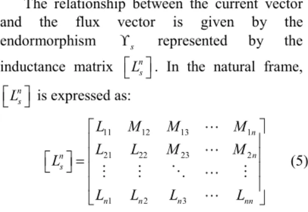
ss depends on i and φsf is due to magnets on the rotor.The relationship between the current vector and the flux vector is given by the endormorphism ϒs represented by the
inductance matrix n s
L
. In the natural frame,
n s L is expressed as: 11 12 13 1 21 22 23 2 1 2 3 n n n s n n n nn L M M M L L M M L L L L L = (5) where Lkk is the self-inductance of the phase k and Ljk is the mutual inductance between the phases j and k.
As mentionned above, the symetrical inductance matrix leads to a base of eigenvectors whose corresponding eigenvalues are given by
[ ]
(
)
det n 0 s n L λ I − = . In this new base defined by Β =d
{
x x1d, , ,2d xnd}
, the matrix of
endomorphism ϒs is given by:
1 2 0 0 0 0 0 0 0 0 d s n L λ λ λ = (6)
Each eigenvalue is associated to an eigenspace whose the dimension depends on the multiplicity of the eigenvalue. For example, if there are two solutions equal to λ1, then the λ1is
belong to a 2-dimensional eigenspace.
It can be noticed that all subspaces (the eigenspaces) are orthogonal and it can be defined as a set of fictitious magnetically independent systems.
For each subspace, the relationship between the voltage and the current is given by:
j j j j j j j d di v Ri Ri e dt dt φ λ = + = + + (7) where e is the back-electromotive force. j
Based on equation (7), we can consider that in the new base, a multiphase can be decomposed into several fictitious machines where each machine is characterized by a resistor R, an inductance λj and a vector of the back-EMF e . j
According to the dimension of the eigenspace where the eigenvalue λjis belong to, the
fictitious machine can be monophase or diphase. Let us take an example in the case of a 3-phase machine. The new base is defined by the Concordia transformation where it exists a double root and a single root of eigenvalues by solving the determination
(
3[ ]
)
3
det Ls−λ I =0. The double root corresponds to the d-q machine and the single root is linked to the homopolar one.
2.3 Applying to a 5-phase machine
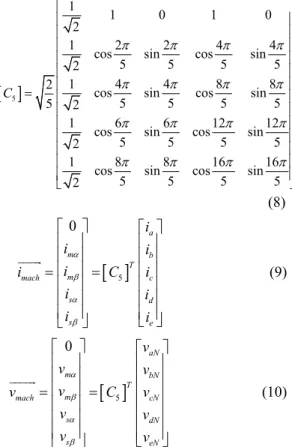
For a 5-phase PMSM, after a generalized Concordia transformation (given in equation (8)) which brings electrical variables of machine to the eigenspace, we obtain thus: one single eigenvalue, two double eigenvalues. It means there are one 1-dimensional fictitious machine and two 2-dimensional ones. They are called respectively homopolar machine, main machine and secondary machine. It is not always the case where these machines exist. Their presence depend on the shape of the back-EMF. Indeed, the homopolar machine is created by harmonics 5*k. The main machine is issue from harmonics 1, 9, 11,…, 5*k ± 1 and the secondary is formed by harmonics 3, 7, 13,…, 5*k ± 2 by considering only odd harmonics [3]. Thus the Main Machine (MM) (resp. the Secondary Machine (SM)) produces Tm (resp. Ts) torque mainly thanks to
the first harmonic (resp. third harmonic) of the back-EMF.
Relationships between actual phase variables (denoted with subscripts a, b, c, d and e) and values of fictitious machines are then defined by:
[ ]
51 1 0 1 0
2
1 cos2 sin2 cos4 sin4
5 5 5 5
2
1 4 4 8 8
2 cos sin cos sin
5 5 5 5
5 2
1 cos6 sin6 cos12 sin12
5 5 5 5
2
1 cos8 sin8 cos16 sin16
5 5 5 5 2 C π π π π π π π π π π π π π π π π = (8)
[ ]
5 0 a m b T m mach c s d s e i i i i i C i i i i i a b a b = = (9)[ ]
5 0 aN m bN T m mach cN s dN s eN v v v v v C v v v v v a b a b = = (10)Currents and voltages obtained using this transformation can be decomposed into two subsystems associated with the main and secondary machines: ; t t m m m s s s t t m m m s s s v v v v v v i i i i i i a b a b a b a b = = = = (11)
As the machine is supplied by a VSI,
vsi mach
v
v
=
and consequently: ; m mvsi s svsi v=v v=v (12) Equations (13) - (16) give the mathematical model of the two fictitious machines in the new reference frame:( )
m m m m d m m v R i L i e dt = + + (13)( )
s s s s d s s v R i L i e dt = + + (14) tot m s T =T +T (15) where : . and . m m m s s s e i = ΩT e i = ΩT (16) Equation (15) means that the total torque of the 5-phase machine is the sum of the torque created by the two fictitious machine. We can consider that there is a fictitious mechanical coupling between them.Controlling a 5-phase machine leads to finally control two equivalent fictitious diphase ones after the Concordia transformation. Each ficitious machine is linked to some harmonics of the back-EMF as discussed previously in section 2.3. There are many works in the literature presenting the control of 5-phase machines under healthy and fault modes [7]-[12]. In both operating modes, physical limits related to voltages and currents of the drive have been also studied [13]-[18]. This paper focuses to control two 5-phase machine having a series connection and they are fed by two isolated DC-buses. III. TWO SERIES-CONNECTED 5-PHASE
PMSM
The studied structure is shown in Fig. 2. The objective is to control independently these two machines. Normally, to do this, only one VSI is required but a higher functional reliability can be achieved by adding another VSI [19], specially in short-circuit inverter switch fault.
Controlling independently two 5-phase machines leads to a necessity of 8 independently currents as degree of freedoms (DOF). In the present structure, there are only 4 currents can be
Fig. 2. Structure of two 5-phase open-end winding machines under study.
N N M1 M2 2’a 2’b 2’c 2’d 2’e
freely controlled. That is why a specific connection between two machines is needed [20].
3.1 Modelling
The special connection between the two machines can be expressed by:
[
]
[ ][
]
[ ]
2 2 2 2 2 2 5 1 1 1 1 1 5 1 T a b c d e T a b c d e i i i i i i L i i i i i L i = = = (17) with: 5 1 0 0 0 0 0 0 0 1 0 0 1 0 0 0 0 0 0 0 1 0 0 1 0 0 L = (18) The vectors i1 and i2 represent the current vectors of the 1st machine M1 and the second one
M2 respectively.
Using equations (9), (17) and the property
1
5 5
[ ]C − =[ ]C T, a relation between the current
vectors of the fictitious machines is given as follows:
[ ]
[ ] [ ]
[ ] [ ][ ]
[ ] [ ][ ]
2 1 2 2 1 2 2 5 2 5 5 1 2 2 1 2 2 1 1 1 5 5 5 5 5 5 1 1 1 0 0 a a m b b T T m mach c c s d d s e e m T T m mach s s i i i i i i i C i C L i i i i i i i i i C L C C L C i i i a b a b a b a b − − = = = = = (19) where:[ ]
5 5[ ]
5 1 0 0 0 0 0 0 0 1 0 0 0 0 0 1 0 1 0 0 0 0 0 1 0 0 T C L C = − (20)Equations (19) and (20) lead to:
1 1 1 2 2 1 1 1 2 2 T T s s s m m T T m m m s s i i i i i i i i i i a b a b a b a b = = = = − (21) or: 1 2 * 1 2 s m m s i i i i = = (22)
Expression (22) lead to two significant things:
• Thanks to the swapping connection between two machines M1 and M2, the currents of the main machine MM1 (second SM1 respectively) of the M1 are linked to the ones of the secondary SM2 (main MM2 respectively) machine of the M2. This allows to control independently two machines M1 and M2 with only 4 free currents.
• In point of view of electromagnetic torque, im1
will create a torque not only for the main machine of M1 but also for the second machine of M2. In the same manner, is1
will contribute to the torque created in the two fictitious machines SM1 and MM2. This leads to a more complex strategy of control to decouple the previous mentioned interaction in order to obtain an independence of the two machines M1 and M2.
This second conclusion is obvious to take into account for multiphase drives. As mentionned above, a multiphase machine can be decomposed into some fictitious ones representing by corresponding harmonics of the back-EMF. The main machine is almost linked to the 1st (fundamental) harmonic while the second
machine is affected to the 3rd harmonic.
Generally, the 3rd harmonic can contribute to the
machine torque but when the machine is operated at high speed (constraint of voltage has to be applied), the current calculation becomes more complex, especially as in degraded mode where some degrees of freedom are lost. That is why until now, there are no analytical solutions for a multiphase machine operating under limit of voltages and currents. For some specific applications as electric vehicle where the drive is almost operated at high speed thanks to the flux weakening operation, a multiphase having sinusoidal back-EMF is preferred.
In this study, two 5-phase PMSM are considered sinusoidal. As a consequence, the back-EMF es1
and es2
does not exist leading to a very simple control strategy. The vector current
1
m
i controls the torque (and/or the speed) of the machine M1 and the vector current is1
is dedicated to the torque (and/or the speed) of the machine M2.
Let’s talk about the voltages limit that two machines can be fed.
1 2 1 2 VSI VSI N N
v
å
=
v
-
v
+
v
(23) with: 1 2 M Mv
å
=
v
+
v
(24) is the sum of the phase voltages of the two machines M1 and M2 and[
]
1 1 1 1 1 1 1 1 1 1 1 T VSI a N b N c N d N e N v = v − v − v − v − v − (25)[
]
2 2 2 2' 2 2' 2 2' 2 2' 2 T VSI a N b N c N d N e N v = v′ − v − v − v − v − (26)[
]
1 2 1 2 1 2 1 2 1 2 1 2 T N N N N N N N N N N N N v = v − v − v − v − v − (27)are the voltages of the two VSI and the voltage between the two negative points of two DC buses, respectively.
Voltages delivered by two VSI can be obtained by some techniques. A Space Vector Modulation has been proposed in [21] to exploit better the two DC-buses. In [22], some simple modulation strategies have been presented for varying the machine voltages according to the rotor speed without flux weanking operation. In
this paper, a bipolar modulation is chosen to maximize the voltage of machines.
It’s interesting to discuss about the voltage sharing between the two machines. Indeed, by observing the equation (24), voltages of M1 and M2 can be shared in the optimal way while respecting the voltage limit fed by two VSI based on the bipolar modulation technique. As the M1 and M2 are independently controlled, an optimal strategy could be employed according to technical specifications of the applications in term of torques and speeds of the two machines M1 and M2. A simplified strategy has been implemented in this work by using
1 2
1
2
M M
v
=
v
=
v
å
.3.2 Control scheme
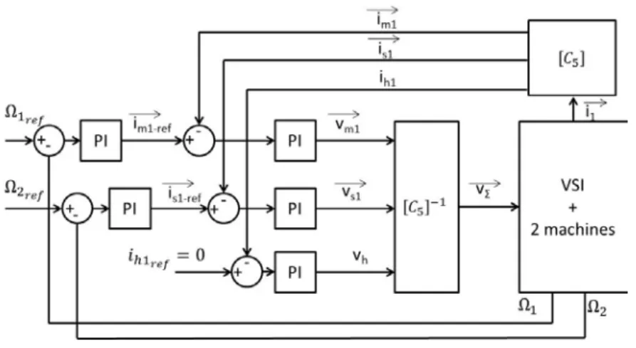
The control scheme is reported in Fig. 3. The two machines M1 and M2 are required to rorate as Ω1ref and Ω2ref. PI controllers are used for
speeds and currents tracking. It can be noticed that only the phase currents of M1 are measured since they are the same ones acrossing the M2 by the
[ ]
L5 transformation.IV. EXPERIMENTAL RESULTS
In order to validate the proposed control strategy, some experimental results have been carried out. Fig. 4. shows the platform for experimental verification. Tab. I. gives some details of the drive parameters. A 5-phase VSI is communicated to a dSPACE 1005 board through an I/O interface. A DC-programmable source is used to feed the drive during motor mode and recover energy during braking.
Fig. 4. Experimental test-bed. TABLE I. DRIVE PARAMETERS
Parameters 5-phase M1 5-phase M2
Phase resistance Rs = 2.24 [Ω] Rs = 9.1 [mΩ]
Phase inductance Ls = 2.7 [mH] Ls = 0.09 [mH]
Mutual induc. 1 M1 = 0.25 [mH] M1 = 0.02
[mH] Mutual induc. 2 M1 = -0.75 [mH] M2 = -0.01[mH]
Pole pair number p = 2 p = 7 back-EMF constant EΩn =0.51 EΩn =0.1358
Max. RMS current 15 [A] 147 [A] Maximum speed 1500 [rpm] 16000 [rpm] Maximum torque 20 [N.m] 50 [N.m] Maximum power 3.1 [kW] 15 [kW]
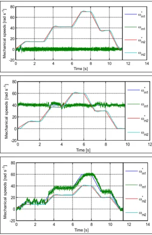
For experimentation tests, the two machines M1 and M2 are operated under speed control.
Fig. 5 gives the experimental verification. Three study cases have been considered. The 1st
one consists to keep the machine M2 at stand-still and the M1 is trained following a speed profile. The second test has been realized by keeping the rotor speed of M2 at 40 rad/s and the M1 is tuned to track a speed profile. For the last case, both machines M1 and M2 are operated at two
Fig. 5. Experimental results in three studied cases: a)
Ω2ref = 0; b) Ω2ref = 40 rad/s and Ω1ref is varying; c)
Both machine’s speeds are varying .
different profiles of speed. Based on the results given in Fig. 5, we can conclude that the proposed control strategy has been verified.
It should be highlighted that there was no strategy for voltage sharing between M1 and M2. The speed profiles were chosen in the way that DC-buses are able to delivery enough voltages for two machines M1 and M2.
V. CONCLUSION
In this paper, a generalized vectorial formalism has been presented and applied for multiphase drives. Based on this approach, two 5-phase PMSM having series connection (through windings) can be independently controlled. However, one assumption that all machines are sinusoidal has been made to simplify to control strategy.
This specific structure is suitable for applications where we have the constraint for compacity and weight of the whole systems.
0 2 4 6 8 10 12 14 -20 0 20 40 60 80 Time [s] M ec hani cal s peeds [r ad s -1] ω* m1 ωm1 ω* m2 ωm2 0 2 4 6 8 10 12 -20 0 20 40 60 80 Time [s] M ec hani cal s peeds [ rad s -1] ω* m1 ωm1 ω* m2 ωm2 0 2 4 6 8 10 12 14 -20 0 20 40 60 80 Time [s] M ec hani cal s peeds [ rad s -1] ω* m1 ωm1 ω* m2 ωm2 5-ph. machine M2 5-ph. machine M1 load 1 5-ph. VSI load 2 dSPACE 1005 Board I/O interface
REFERENCES
[1]. H. Jin, K. Min, Y. Jia-qiang, J. Hai-bo, and L. Dong, "Multiphase machine theory and its applications," in Electrical Machines and
Systems, 2008. ICEMS 2008. International Conference on, 2008, pp. 1-7.
[2]. E. Levi, "Multiphase Electric Machines for Variable-Speed Applications," Industrial
Electronics, IEEE Transactions on, vol. 55, no.
5, pp. 1893-1909, 2008.
[3]. E. Semail, A. Bouscayrol, and J. P. Hautier, "Vectorial formalism for analysis and design of polyphase synchronous machines," European
Physical Journal-Applied Physics, vol. 22, no. 3,
pp. 207-220, Jun 2003.²
[4]. X. Kestelyn, E. Semail, and J. Hautier, "Vectorial multi-machine modeling for a five-phase machine," International Congress on
Electrical Machines (ICEM’02), 2002.
[5]. L. Parsa and H. A. Toliyat, "Five-phase permanent-magnet motor drives," Industry
Applications, IEEE Transactions on, vol. 41, no.
1, pp. 30-37, 2005.
[6]. E. Semail, E. Levi, A. Bouscayrol, and X. Kestelyn, "Multi-machine modelling of two series connected 5-phase synchronous machines: effect of harmonics on control," in Power
Electronics and Applications, 2005 European Conference on, 2005, pp. 10 pp.-P.10.
[7]. A. Mohammadpour, S. Mishra, and L. Parsa, "Fault-Tolerant Operation of Multiphase Permanent-Magnet Machines Using Iterative Learning Control," Emerging and Selected Topics in Power Electronics, IEEE Journal of, vol. 2, no. 2, pp. 201-211, 2014.
[8]. S. Dwari and L. Parsa, "An Optimal Control Technique for Multiphase PM Machines Under Open-Circuit Faults," Industrial Electronics, IEEE Transactions on, vol. 55, no. 5, pp. 1988-1995, 2008.
[9]. S. Dwari and L. Parsa, "Fault-Tolerant Control of Five-Phase Permanent-Magnet Motors With Trapezoidal Back EMF," Industrial Electronics, IEEE Transactions on, vol. 58, no. 2, pp. 476-485, 2011.
[10]. X. Kestelyn and E. Semail, "A Vectorial Approach for Generation of Optimal Current References for Multiphase Permanent-Magnet Synchronous Machines in Real Time," IEEE Transactions on Industrial Electronics, vol. 58, no. 11, pp. 5057-5065, Nov 2011.
[11]. D. Flieller, N. K. Nguyen, P. Wira, G. Sturtzer, D. O. Abdeslam, and J. Merckle, "A Self-Learning Solution for Torque Ripple Reduction for Nonsinusoidal Permanent-Magnet Motor Drives Based on Artificial Neural Networks," Industrial Electronics, IEEE Transactions on, vol. 61, no. 2, pp. 655-666, 2014.
[12]. D. Flieller, N. K. Nguyen, H. Schwab, and G. and Sturtzer, Control of Non-Conventional
Synchronous Motors. Chapter 3: Synchronous Machines in Degraded Mode, ISTE Ltd and John
Wiley & Sons Inc., 2012.
[13]. L. Parsa, N. Kim, and H. A. Toliyat, "Field Weakening Operation of High Torque Density Five-Phase Permanent Magnet Motor Drives," in
Electric Machines and Drives, 2005 IEEE International Conference on, 2005, pp.
1507-1512.
[14]. H. A. Toliyat, "Analysis and simulation of five-phase variable-speed induction motor drives under asymmetrical connections," Power
Electronics, IEEE Transactions on, vol. 13, no.
4, pp. 748-756, 1998.
[15]. L. Lu, E. Semail, L. Kobylanski, and X. Kestelyn, "Flux-Weakening Strategies for a Five-Phase PM Synchronous Machine," Proceedings of the 2011-14th European
Conference on Power Electronics and Applications (EPE 2011), pp. 1-7, 2011.
[16]. S. Zhigang, W. Jiabin, G. W. Jewell, and D. Howe, "Enhanced Optimal Torque Control of Fault-Tolerant PM Machine Under Flux-Weakening Operation," Industrial Electronics,
IEEE Transactions on, vol. 57, no. 1, pp.
344-353, 2010.
[17]. O. Fall, J. F. Charpentier, N. K. Nguyen, and P. Letellier, "Maximum torque per ampere control strategy of a 5-phase PM generator in healthy and faulty modes for tidal marine turbine application," in Electronics and Application
Conference and Exposition (PEAC), 2014 International, 2014, pp. 468-473.
[18]. L. Li, B. Aslan, L. Kobylanski, P. Sandulescu, F. Meinguet, X. Kestelyn, and E. Semail, "Computation of optimal current references for flux-weakening of multi-phase synchronous machines," in IECON 2012 - 38th Annual
Conference on IEEE Industrial Electronics Society, 2012, pp. 3610-3615.
[19]. N. K. Nguyen, F. Meinguet, E. Semail, and X. Kestelyn, "Fault-Tolerant Operation of an Open-End Winding Five-Phase PMSM Drive with Short-Circuit Inverter Fault," Industrial
Electronics, IEEE Transactions on, vol. PP, no.
99, pp. 1-1, 2015.
[20]. F. Mekri, J.-F. Charpentier, and E. Semail, "An efficient control of a series connected two-synchronous motor 5-phase with non sinusoidal EMF supplied by a single 5-leg VSI: Experimental and theoretical investigations,"
Electric Power Systems Research, vol. 92, no. 0,
pp. 11-19, 2012.
[21]. E. Levi, I. N. W. Satiawan, N. Bodo, and M. Jones, "A Space-Vector Modulation Scheme for Multilevel Open-End Winding Five-Phase Drives," Energy Conversion, IEEE Transactions on, vol. 27, no. 1, pp. 1-10, 2012.
[22]. N. K. Nguyen, E. Semail, F. Meinguet, P. Sandulescu, X. Kestelyn, and B. Aslan, "Different virtual stator winding configurations of open-end winding five-phase PM machines for wide speed range without flux weakening operation," in Power Electronics and
Applications (EPE), 2013 15th European Conference on, 2013, pp. 1-8.