Science Arts & Métiers (SAM)
is an open access repository that collects the work of Arts et Métiers Institute of Technology researchers and makes it freely available over the web where possible.
This is an author-deposited version published in: https://sam.ensam.eu
Handle ID: .http://hdl.handle.net/10985/19601
To cite this version :
X.F. GUO, Adil BENAARBIA, W. SUN, A. BECKER, A. MORRIS, M. PAVIER, P. FLEWITT, M. TIERNEY, C. WALES - Optimisation and thermo-mechanical analysis of a coated steam dual pipe system for use in advanced ultra-supercritical power plant - International Journal of Pressure Vessels and Piping - Vol. 186, p.104157 - 2020
Any correspondence concerning this service should be sent to the repository Administrator : archiveouverte@ensam.eu
Axisymmetric
2D model
O
p
tim
is
a
tio
n
D
e
si
g
h
Thermo- mechanical analyses1
Optimisation and thermo-mechanical analysis of a coated steam dual
pipe system for use in advanced ultra-supercritical power plant
X.F. Guo a,∗, A. Benaarbia b, W.Sun a, A. Becker a, A. Morris c, M. Pavier d, P. Flewitt d, M.Tierney d, C. Wales d
a Department of Mechanical, Materials and Manufacturing Engineering, University of
Nottingham, Nottingham, NG7 2RD, UK
b Arts et Métiers, CNRS, Université de Lorraine, LEM3, F-57000 Metz, France
c EDF Energy (UK), Coal Gas and Renewables, Central Technical Organisation, Barnwood,
Gloucester, GL4 3RS, UK
d Department of Mechanical Engineering, University of Bristol, Bristol, BS8 1TR, UK
Abstract: Improving the energy efficiency of power plants by increasing steam
operating temperature up to 700 °C can be achieved using novel engineering design concepts such as coated steam pipe systems. This paper presents an optimised design for a novel coated dual pipe system to be used in advanced ultra-supercritical power plant. The approach developed in this study uses a combination of an optimisation algorithm and FE simulation, based on the reduction of the hoop stress at top coat/bond coat interface generated by the thermal and mechanical stresses. This allows determination of the optimum dimensions and material properties of the system. A unified viscoplastic model which combines a power flow rule with non-linear anisothermal evolution of isotropic and kinematic hardening has been used for the thermo-mechanical analysis of the coated dual pipe system under the cyclic loading. The results of the optimisation show that the value of the hoop stress at the top coat/bond coat interface is reduced significantly, compared with that in the baseline model. Finally, the potential technical challenges and future works for the proposed steam dual pipe system are discussed.
Keywords: Thermal barrier coating, Dual pipe system, System optimisation, Cyclic
viscoplasticity
*Corresponding author.
E-mail address: guoxiaofeng@njtech.edu.cn (Xiaofeng Guo)
2
Currently, there is an increasing demand to improve the thermal efficiency of power plant by increasing steam-operating temperatures [1-3]. Several advanced ultra-supercritical power plants with target steam temperature up to 700 °C have been proposed to achieve cycle efficiencies in the order of 55% [4-5]. Using conventional steam cycle design, such high operation temperatures require the use of nickel-based alloys such as Inconel 740, Haynes 230 and CCA 617, to replace the traditional 9-12%Cr ferritic heat resistant steels. These high temperature materials are of great importance for power plant components (superheaters, reheaters, steam transfer pipes, etc.) due to their resistance to creep damage and steam oxidation [6-7]. However, nickel-based alloys are significantly more costly than 9-12%Cr steels and are in relatively scarce supply. An alternative plant design is therefore required to achieve higher steam operating temperatures at an acceptable cost.
Thermal barrier coatings (TBCs), especially partially stabilized zirconia-yttria (YSZ), have been widely used in aircraft and industrial gas-turbine engines to provide thermal insulation and oxidation protection for superalloy components[8-10]. Inspired by this approach, a steam transfer piping system operating at steam temperatures of up to 700°C has been designed to improve the energy efficiency of advanced ultra-supercritical power plants without the use of nickel-based alloys [11]. Fig. 1 exhibits a schematic illustration of the coated pipe system where an internal (primary) steam pipe conveys steam from the boiler outlet to the high-pressure steam turbine with an external (secondary) steam pipe conveying the counter-cooling steam [11]. Due to the use of low-thermal conductivity thermal insulation coating and a counter-cooled pipe system, the coated primary steam pipe has a significant thermal gradient through the wall thickness, and therefore large thermal stresses will be generated during start-up, shut down and steady-state operations. The geometry and material properties of the TBC system, particularly those of the top coat layer, greatly affect the thermal insulation capacity and also the generation of thermal-expansion mismatch stresses. These stresses may be large enough to influence the structural integrity of the system.
In order to analyse the thermal and mechanical response of the dual pipe system, preliminary analyses have been carried out by Guo et al [12] based on analytical solutions and finite element analyses. The effects of several factors, for example the top coat thickness, thermal expansion coefficients and the temperature of the cooling steam on the temperature and stress distributions of the system, have been identified.
3
Although these factors were found to have a significant effect, no attempt was made to optimise the material properties or the dimensions of the system.
Due to fluctuating energy demand and market competition, more frequent cyclic operation is witnessed in current power plant operation. This has led to the prevalence of high temperature damage mechanisms, such as creep and creep-fatigue. In past decades, the modelling of both fatigue and creep behaviours of high temperature materials has achieved significant progress, especially within a cyclic viscoplasticity framework [13-23]. Generally speaking, this framework can be split into two broad groups: unified and non-unified viscoplasticity. In unified viscoplasticity, viscous creep and plastic strains are represented by a single inelastic measure and considered as rate-dependent [13, 19, 23]. In non-unified viscoplasticity, both strains are considered as separate measures, where the creep strain is taken to be rate-dependent and the plastic strain to be rate-independent [24-25]. Constitutive models with specific isotropic and kinematic hardening rules have been developed for different materials [26-29]. Chaboche [30] has presented a review of many of these models. However, only few models available in literature are able to predict the anisothermal fatigue behaviour of the investigated material [19, 31-32]. In this work, a unified viscoplastic model with non-linear anisothermal isotropic and kinematic hardening formulations is used to carry out the thermo-mechanical analyses.
This study describes an optimised design methodology based on a thermo-mechanical analysis of a novel coated dual pipe system for use in advanced ultra-supercritical power plant. The optimisation procedure is presented in section 2, where the theoretical formulations of model are introduced. In section 3, the finite element approach is presented, including a description of the viscoplastic model and the associated model parameters for the coating system. Section 4 discusses the system parameter optimisation and the significance of the results by comparing the stress evolutions in the baseline simulation and optimised models. Finally, a FE analysis of the dual pipe system under cyclic loading is performed using the viscoplastic model to evaluate the developed optimisation model.
2.
Optimisation of the dual pipe system
In order to discuss the thermal and stress distributions of the coated dual pipe system generated during steady-state operation, a one-dimensional model of the
4
coating-pipe structure has been built up in previous work[12]. There are 3 layers, the top coat (TC), bond coat (BC) and the substrate pipe in the model. The sectional diagram of the system is shown in Fig. 2.
2.1
Optimisation model
In this work, the thermal-expansion mismatch stresses at the TC and BC interfaces are taken to be the critical factor leading to failure of the TBC system[8,12]. The optimisation model is therefore
= − → min, (1) ∈ , (2) ≤ ≤ , = 1, 4 (3) where is the objective function, is the optimisation variable set (a vector in the n-dimensional space, ). In terms of the key governing parameters which have been identified [12], the optimisation variable set is
= # $%, $&, '(, )* + , (4) where $% is the thickness of the TC, $& is the thickness of primary pipe, '( is the thermal conductivity of the TC, )* is the hydraulic mean diameter in the cooling jacket [11]. and are the hoop stresses on the outer surface of the TC and on the inner surface of the BC. and are the lower and upper bounds of .
No lower limit is imposed on the value of $% since the TC layer needs to be as thick as necessary to reduce the temperature of the primary pipe to the required level. At present, the maximum thickness of the coating tested in open literature is 4 mm [11,33]. However, if the TC layer is too thick, it will lead to accelerated failure [8]. Thus, the upper boundary for $% is chosen to be 3 mm. Some practical engineering dimension constraints have been imposed during the optimisation analysis, so the boundaries for
$& can be selected to be between 30 mm and 60 mm, and )* between 100 mm and 200
mm. Changes to the value of )* will affect the flow of steam in the cooling jacket and therefore the heat transfer coefficient between the primary pipe and the steam. These additional effects have not been considered in this work. Additionally, in order to cover a wide range of possible coating materials, the boundaries for '( can be chosen to be between 1.0 and 1.5 W/m°C[34-36].
5
The thermal efficiency of the dual pipe system is considered as a constraint in the optimisation model. The thermal efficiency is calculated following the work of Wales et al [11]. The thermal efficiency constraint inequality is defined as
, − ,- ≥ 0, (5)
where , is the thermal efficiency constraint function while ,- stands for the threshold value of thermal efficiency. Here, considering the operating costs and profitability of power plants, ,- is set as 51.40% [11].
In the current coated dual pipe system, superheated steam at 700°C is transported using the coated P91 pipe so that the temperature experienced by the primary P91 pipe does not exceed 580°C. This temperature constraint of the primary pipe is set in the optimisation model. The temperature constraint equation is expressed as
0 − 0- ≤ 0,
6 where 0 is the temperature constraint function, 0- is the maximum temperature of the primary temperature (580°C), as described in Fig. 2.
Arbitrary values of $%, $&, '( 234 )* are used as initial values and the proposed algorithm is used to find optimised values of $%, $&, '( 234 )*.
2.2
Optimisation procedure
In order to determine the optimum dimensions and material properties of the dual pipe, a combined FE simulation and optimisation approach is used. The optimisation is implemented using Matlab. The function for solving the minimum of constrained nonlinear multi-variable functions, fmincon, is provided within the Matlab optimisation toolbox.
A detailed description of the FE simulation is given in section 3.1. Since the initial guess values for $%, $&, '( 234 )* are provided, these parameters are passed into the Abaqus input file by using a Matlab programme, and then a sequentially coupled thermo-mechanical analysis is carried out to obtain the initial hoop stress data within the system for each iteration. Additionally, a series of iterative calculations are also performed with different optimised parameters which are determined from the Matlab optimisation programme. During each iteration, all the system parameters in the Abaqus input file are updated by the new ones based on the FE analysis pre-processing. In the FE post-processing, a python script is used to extract the hoop stresses at the TC
6
and BC interfaces from the Abaqus output file. All the optimisation procedures run automatically until convergence is reached. The optimisation algorithms used in this study are illustrated in Fig. 3, where the thermal efficiency calculation module is also included [11].
3.
Finite element models of the coated dual pipe system under
thermo-mechanical loading
3.1
Thermal and stress analysis models under steady-state
operation
Assuming closed end conditions with no system loading (i.e. the stresses present are owing to internal pressure and external pressure only)[37], a coated straight pipe of constant section may be greatly simplified to the 2-D axisymmetric finite element model, as shown in Fig. 4. The uncoupled thermal simulation is first performed in a heat transfer procedure, followed by the stress analysis which closely depends on the temperature field of the system.
3.1.1
Geometry and meshing
In section 4, the results corresponding to the optimised parameters will be compared with the values of those parameters used in previous work[12]. These parameters are referred to here as the baseline parameters and are as follows: the thickness of the TC is 2.5 mm, the inner radius of the primary P91 steam pipe is 120 mm and the wall thickness is 60 mm (Fig. 4). To generate a compatible oxide to enable the ceramic to adhere to the underlying steel pipe, a thin BC layer of 0.5 mm in thickness is assumed. 8-node isoparametric quadratic axisymmetric temperature and continuum elements with reduced 2×2 integration (Abaqus element types DCAX8 and CAX8R) are used for the thermal and stress analyses. The model consists of 63,500 elements with 191,755 nodes to guarantee adequate computational accuracy.
3.1.2
Material properties
The materials of the TC, BC and internal steam pipe used in this study are assumed to be isotropic and homogeneous, and all layers in TBCs are assumed to be elastic and viscous as proposed in literature [38]. Here, 8YSZ, NiCoCrAlY, and P91 steel are chosen as the candidate TC, BC and the substrate, respectively. Some temperature dependent material properties of the TC, BC and the substrate required for the FE
7
models, such as Young's modulus (E), yield strength, density, coefficient of thermal expansion (CTE), conductivity and specific heat, are taken from literature[38-41]. Other properties over a wider range of temperatures can be estimated based on linear interpolation of the existing data. These are given in Table 1.
3.1.3
Boundary conditions
In the baseline simulation conditions, the internal primary steam pipe is set to operate at a temperature up to 700°C, with the second outer cooling steam pipe at a temperature of 450°C. To maintain accurate boundary conditions, a mean axial stress ( 5) is applied to represent the closed end with a constant displacement constraint. Symmetric boundary conditions are used as indicated in Fig. 4. The internal steady state pressure of the primary steam pipe is set at 35 MPa, with the steam pressure of the counter-flow at 7.5 MPa [11-12].
3.2
Anisothermal FE model under cyclic loading
Compared with a constant and relatively uniform wall thickness temperature in a conventional steam circuit operating under steady-state conditions with well lagged piping, the coated dual pipe system has a significant thermal gradient through the wall thickness. Also, the effect of temperature on the material properties should be considered. Operating conditions for future ultra-supercritical power plants, such as expected cyclic mechanical loadings to accommodate increasing levels of renewable energy on the grid, will give rise to creep-fatigue damage of the system. Therefore, analysis of the TBC system is carried out using an anisothermal unified viscoplastic model. To demonstrate the effectiveness of the optimisation method, anisothermal FE analyses of the system before and after optimisation are also performed.
3.2.1
The constitutive model
In this study, an improved unified Chaboche-Lemaitre constitutive model presented in [32] is employed to describe the anisothermal creep-fatigue response of the material under investigation. The main constitutive equations can be described as below 67 = 687+ 6:&7 ,
(7) 687 = ) 7;< => ;<, (8)
8
6?:&7 = @?A7 =B〈ED 〉 GGHIHI== HIHI , (9)
JK , 7, ; 0M = N K 7, 7M − K0, @ 0 M − ' 0 , (10)
where 67, 687 and 6:&7 are the total strain, elastic strain and viscoplastic strain tensors. The viscoplastic strain rate 6?:&7 is expressed by a power flow law where @? is the viscoplastic multiplier rate, defined as @? = OB6?:&7 : 6?:&7 and A7 the viscoplastic flow direction. Q 0 and 3 0 are the temperature dependent material parameters which represent the viscoplastic resistance and hardening exponent functions. R7 is the deviatoric stress tensor of the Cauchy stress tensor, 7, defined as R7 = 7−>B ;;S7.
7 denotes the back stress tensor while the von Mises yield function J is dependent on
the drag stress, 0, @ 0 , with the viscoplastic multiplier, @, the yield stress, ' 0 , and the second invariant N . The N -term is expressed by
N K , 7M = OBKR7− 7MKR7− 7M, (11)
In this constitutive model, the anisothermal evolution of the kinematic hardening parameter 7 using the Chaboche decomposition [30] is given as
7 = ∑; >, 7; , (12)
? 7; 0 = U ; 0 V2
3 Y ; 0 6?:&7 − 7; 0 @?Z
+ [#U ; 0 +=>U
,; 0 + #Y ; T +=>Y,; 0 ]^ 7; 0 0?, (13)
where U ; 0 and Y ; 0 are the temperature dependent material parameters. The terms U,; 0 and Y,; 0 represent the partial derivative of U ; 0 and Y ; 0 with respect to the temperature. The anisothermal evolution of the drag stress R can be expressed by
?K0, @ 0 M = #_ 0 − K0, @ 0 M + `=> 0 a 0 +` 0 @? 0
9
where _ 0 and ` 0 are temperature dependent material properties and a 0 represents the linear drag stress evolution. The terms a, 0 , `, 0 and _, 0 are the partial derivatives of a 0 , ` 0 and _ 0 with respect to temperature. The detailed theoretical derivation of 7 and K0, @ 0 M can be found in [32].
3.2.2
Material model parameters
A bespoke user material subroutine (UMAT) for the unified viscoplastic model described here has been generated in previous work [32,42]. The associated temperature dependent material properties of the P91 steel are given in Table 2. The UMAT used in this study was calibrated and validated using a series of isotropic hold-time cycle tests conducted at different temperatures as reported in several papers [17, 43-44]. For the TC and BC layers, the temperature-dependent Young’s modulus and yield stress are taken from literature [38-41]. Other temperature-dependent material properties are taken to be equal to those of the P91 steel.
3.2.3
Cyclic thermo-mechanical loading
In this work, a simplified cyclic thermal and mechanical loading for the dual pipe system has been used, as shown in Fig. 5. The loading starts from a stress-free state at 20°C, and consists of a number of repeating cycles with thermal and mechanical loadings. For the thermal loading, each cycle of the inner surface of the TC is composed of a 6 hour heat-up period from 20°C to 700°C, a 72 hour dwell period at 700°C, a 5 hour cool-down period from 700°C to 20°C and a 7 hour dwell period at 20°C. The external surface of the primary pipe is exposed to a 6 hour heat-up period from 20°C to 450°C, a 72 hour dwell period at 450°C, a 5 hour cool-down period from 450°C to 20°C and a 7 hour dwell period at 20°C. In addition to the thermal loading, the internal and external pressures varying with time are imposed on the inner and outer surfaces of the coated primary pipe system. The mechanical loading cycle also consists of a 6h period of start-up and a 5h shutdown with a 72h dwell period at full power in between, followed by a 7h dwell period at rest. It represents the typical high energy demand in the market, when the main steam pipeline is turned on; when the demand falls and they are turned off. The peak magnitude of the internal and external pressures described in section 3.1.3 are achieved during the 72 hour period.
10
4.1 System optimisation analysis
4.1.1 Optimisation of the system parameters
The procedures described in Sections 2 and 3 will now be used to determine the optimised system parameters of the dual pipe system. To avoid affecting optimisation results caused by the differences in the magnitude of optimisation variables, the values of the variables have been normalised to the same order of magnitude during optimisation. The procedure starts from initial guessed values for $%, $&, '( 234 )*
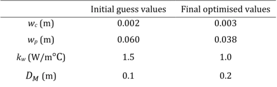
(the baseline values defined in section 3.1.1) and continues by performing iterations to find the minimum value of the hoop stress mismatch at the TC/BC interface. The convergence history of the optimised results is shown in Fig. 6. The results show that the values converge after 23 iterations. Additionally, it can be seen that the optimisation variables of $%, $&, '( 234 )* converge rapidly after 5 iterations and the hoop stress mismatch at the TC/BC interface caused by the thermal and mechanical stresses reaches a minimum (see. Fig. 7). However, at this point the thermal efficiency of the system is less than the constrained value of 51.40% which is set as a constraint in the optimisation model. In order to increase the thermal efficiency, the thickness of the primary pipe $& must be increased to recover the thermal efficiency to the constrained value, since this increase of $& can reduce the significant influence of the cooling system on the thermal efficiency. Thus, it can be observed from Fig. 6 that $& starts to increase after 13 iterations, whereas the values of $%, '( 234 )* are almost unchanged during iteration. Table 3 compares the set of optimised values with the initial guessed values.
4.1.2
Comparisons of temperature and stress distributions in the
baseline and optimised models
Fig. 8 presents the temperature and stress distributions through the wall thickness of the coated primary pipe for the baseline geometry. The use of the thermal insulation coating reduces the inner surface temperature of the substrate pipe to about 560°C. The resulting temperature gradient through the wall thickness seen in Fig. 8(a) inevitably gives rise to large thermal stresses within the system.
The stress distribution of the coated primary steam pipe system through the wall thickness is shown in Fig. 8(b). The radial stress is continuous through the wall
11
thickness, whereas the hoop stress is discontinuous across the interfaces at the TC/BC and BC/substrate. The magnitude of the radial stress is quite small compared to that of the hoop stress which therefore plays a dominant role in determining the structural integrity of the system. This hoop stress is composed of a part generated by the thermal loading and a part generated by the mechanical pressure loading. The thermal part is much larger than the mechanical part, so the regulation of thermal stresses presents the key technical challenge. As observed in Fig. 8(b), in addition to the maximum hoop stress distributed on the external surface of the primary pipe, the positive hoop stress at the TC/BC interface is about 185 MPa due to the thermal expansion mismatch at the interface. Also, the variation of von Mises stress through the wall thickness can be seen in Fig. 8(b). Note from Fig. 8(b) that a peak value of von Mises stress can be observed at the TC/BC interface, but the stress decreases significantly on both sides of the peak.
Fig. 9 shows the temperature and stress distributions in the optimised primary steam pipe system. It can be seen in Fig. 9(a) that the inner surface temperature of the primary pipe reaches 518°C under the steady-state operation, as the TC thickness increases to 3 mm. The temperature difference between the inner and outer walls of the primary pipe changes from 110°C in the baseline model to 68°C in the optimised model. This can be attributed to the increase in TC thickness ($%) and the decrease of the primary pipe thickness ($&). The value of the hoop stress mismatch at the TC/BC interface reduces from 522 MPa in the baseline model to 472 MPa in the optimised model. The maximum von Mises stress is located at the TC/BC interface during steady-state operation, and its value decreases from 326 MPa in the baseline model to 253 MPa in the optimised model. As the mechanical loadings are the same in the baseline model and the optimised model, the decrease in the stresses is mainly due to the decrease of thermal stresses in the coated dual pipe system. In the optimised system, the decrease of the primary pipe thickness as well as the temperature difference between the inner and outer walls of the primary pipe contributes to the reduction of thermal stresses.
4.2
Anisothermal FE analyses under cyclic loading
It is likely that the coated dual pipe system will experience cyclic mechanical loadings in service and this may lead to creep-fatigue. As described in section 4.1.2, there is a significant stress mismatch at the TBC interfaces, especially around the interface between the TC and BC, under steady-state operating conditions. Moreover,
12
during start-up and shut-down operations, several cycle-dependent phenomena often take place within the TBC system, which may ultimately give rise to the premature failure by interfacial delamination. Therefore, preliminary thermo-mechanical analyses have been carried out using the anisothermal viscoplastic model, as described in section 3.2.1.
The hoop stress and von Mises stress distributions through the wall thickness in the optimised model generated during the first cycle at the end of steady-state and shut down operations are shown in Fig. 11, which can be compared with distributions for the baseline model in Fig. 10. During the first cycle at the end of steady-state operation, Fig. 10 shows that the maximum von Mises stress is located on the external surface of the P91 pipe. In the optimised model, the position of the maximum von Mises stress changes from the external surface of the P91 pipe to the TC/BC interface (Fig. 11). During the first cycle at the end of shut-down, the maximum von Mises stress for both the baseline and optimised conditions is located on the internal surface of the TC, as shown in Fig. 10 and Fig. 11. Moreover, comparing Fig. 10 and Fig. 11, it is clear that the value of the maximum von Mises stress for the baseline model is much larger than for the optimised model. Since the maximum von Mises stress located on the internal surface of the TC in the coated dual pipe system during shut-down is much larger than during steady-state operation in the model, TBC failure may be caused by spallation of the TC. This result is consistent with the experiment observation reported by Padture et al. [8].
5.
Discussion
5.1 An analytical optimisation method
In this work, a procedure has been developed to optimise the design of the dual pipe system. However, since the procedure involves an interaction between Abaqus and Matlab, it is complicated and time consuming.
Alternatively, an analytical optimisation method can be developed using the same objective function, based on the analytical solution of the thermal stresses presented in previous work [12]. Using this method, the temperature profile within the dual pipe system during steady-state operation can be expressed as
0 r = − e ;fH
H 4g +
13
where Ti(r) and ki(r) are the temperature and conductivity coefficients at the i-th
layer, Ai and Bi are the integral constants.
The axial stress, H g , and hoop stress, H g , at the i-th layer caused by the thermal stress are given by
H g = − iH >=jH kHe ∆0 m g g4g + iHnH >hjH >= jH − iHoH >hjH , (16) H g = iH >=jH kHe ∆0 m g g4g + iHnH >hjH >= jH + iHoH >hjH − iHkH >=jH0 g , (17) where Eiis the modulus of elasticity, νq is Poisson’s ratio, αi is the coefficient of linear
thermal expansion, ∆Tq r is the change in the temperature at the i-th layer. Ci and Di are
the constants of integration.
In the previous work, it has been proven that the analytical model above is capable to calculate the temperature profiles and thermal stress fields of the coated steam dual pipe system during steady state operation [12]. Here, the initial hoop stresses at the TC and BC interfaces can be obtained by Eq. (17) followed by calculations of the optimised hoop stresses using updated system parameters determined from the Matlab optimisation processes. The entire optimisation process is executed continuously until convergence is reached. The optimisation algorithm is shown in Fig.12, where the thermal efficiency calculation is also included. Using this method, FE analysis can be avoided, although it would be diffiucult to extend the calculations to include non-steady state conditions.
5.2 Alternative objective functions
As described, the optimisation procedure attempts to reduce the hoop stress mismatch at the TC/BC interface. For such a complex system, other objective functions to represent typical failure mechanisms can also be used to optimise the system, such as the maximum temperature experienced by the primary P91 pipe and the thermal efficiency of the complete system. Another potential parameter that could be considered is the strain range in the TBC, since larger strain excursions associated with larger temperature excursions are more damaging.
Significant progress has been made in understanding the physical damage and failure mechanisms of the TBC system[8]. During start-up, shut-down and steady state operations, several interrelated time and cycle-dependent phenomena, such as the
14
formation of thermally grown oxides (TGO), may take place in the coated dual pipe system. In general, the large thermal-expansion mismatch among the TC, TGO and BC can create a significant stress field in the TBCs system [45-46]. With the growth of the TGO during service condition, the stress at the BC and TGO interface can ultimately result in interface cracking and system failure by spallation of the top-coat. The thickness of the TGO could be used as the objective function to optimise the dual pipe system since it is one of the most important factors controlling the integrity of the TBC system. In addition, thermal mechanical fatigue may also be a typical failure mechanism of the system. Because the fatigue failure depends more on the stress amplitudes, which may be considered as an alternative objective function to optimize the system.
Based on the analysis above, many factors can be used as the objective function to optimise the structure of the dual pipe system. For the current complex optimisation problem, different objectives under consideration may conflict with each other, and optimising a particular solution with respective to a single objective can result in unacceptable results with regard to the other objective. To solve this problem, a reasonable solution is to use multi-objective optimisation method which weights the importance of all the key factors (for example the maximum temperature experienced by the primary P91 pipe, the thermal efficiency of the system and the thickness of the TGO) in the same optimisation function [47].
5.3
Thermal efficiency
In the proposed dual pipe system, the use of a counter-cooled pipe system will inevitably result in a loss of heat from the supercritical steam and therefore contribute to the loss of thermal efficiency of the system. This will partly offset the higher efficiency achieved from the initially much higher superheated steam temperature. The calculation of thermal efficiency [11] for an ideal system with no zero heat and pressure losses gives a figure of 51.8%. This compares with 52.4% for a conventional design using materials that can withstand the temperature of the supercritical steam.
The parameters used in the optimisation procedure, $%, $&, '(, and )*, have a significant impact on the thermal efficiency of the system. To improve the efficiency, values for $%, $&, 234 )* should be as high as possible, while '( should be low. Of the 4 parameters, $&, the thickness of primary pipe was found to be the most important parameter: a lower value for $& gives a reduced stress mismatch at the TC/BC interface.
15
Fig.13 shows effect of $& on cycle thermal efficiency. The value for $&needs to be a compromise between improving efficiency and reducing the stresses in the TBC.
6.
Conclusions and future work
In this work, an optimised design methodology has been developed based on a thermo-mechanical analysis of a novel coated dual pipe system for use in advanced ultra-supercritical power plant. In addition, a FE analysis of the system under cyclic loading has been performed using the viscoplastic model to evaluate the developed optimisation model. The main conclusions are as follows:
1. A combined FE simulation and optimisation algorithm is developed which is capable of determining the optimised dimensions and material properties by calculating the hoop stress mismatch at the TC/BC interface generated by the thermal and mechanical loadings. FE analyses are carried out to calculate the temperature profiles and stress distributions of the system in the baseline and optimised models. The results show that the value of hoop stress mismatch at TC/BC interface decreases from 522 MPa in the baseline model to 472 MPa in the optimised model, and the value of the maximum von Mises stress reduces from 326 MPa to 253 MPa.
2. The current study has demonstrated the methods of performing thermo-mechanical analysis under cyclic loading for the coated dual pipe system using a unified viscoplastic model with non-linear anisothermal isotropic and kinematic hardening rules. The comparison results before and after optimisation show that the value of the maximum von Mises stress of 1360 MPa in the baseline model during shut down is much larger than that in the optimised model of 453.7 MPa.
3. An analytical optimisation method, which includes both heat transfer and thermal stress calculations, is also developed to determine the dimensions and material properties of the coated dual pipe system, although it would be difficult to extend the calculations to include non-steady conditions.
This study demonstrates the feasibility of using high temperature materials in current widespread use, for significantly higher temperature application in ultra-supercritical plant designs. This higher temperature application necessarily requires novel design options to be considered. This study has demonstrated how modelling and optimisation techniques can be used to explore the design feasibility of the proposed coated dual pipe system. The integrity of the interface between the TBC and primary
16
steam transfer pipe presents a key technical challenge. Further development of coating systems and testing is required to demonstrate the successful operation of the proposed dual pipe system. Several time- and cycle-dependent phenomena, such as the formation of a thermally-grown oxide layer, the interdiffusion of high concentration elements between different interfaces as well as premature spallation failure require further investigation.
Acknowledgements
This work is supported by Engineering and Physical Sciences Research Council (EPSRC), United Kingdom, through the project “Novel High Temperature Steam Transfer Pipes” [Grant number: EP-R000859-1] and the National Natural Science Foundation of China (51805274). The authors would also like to thank EDF UK for technical support.
References
[1] M.Q. Ou, X.C. Hao, Y.C. Ma, R.C. Liu, L. Zhang, K. Liu, Effect of carbon on the microstructure and stress rupture properties of a new Ni-Cr-W-Fe alloy for advanced ultra-supercritical power plants, J. Alloy. Compd. 732 (2018) 107-115.
[2] F. Sun, Y.F. Gu, J.B. Yan, Z.H. Zhong, M. Yuyama, Phenomenological and microstructural analysis of intermediate temperatures creep in a Ni-Fe-based alloy for advanced ultra-supercritical fossil power plants, Acta. Mater. 102 (2016) 70-78.
[3] F. Abe, Progress in creep-resistant steels for high efficiency coal-fired power plants, J. Press. Vess-t. Asme. 138 (2016) 1-21.
[4] R. Viswanathan, J.F. Henry, J. Tanzosh, G. Stanko, J. Shingledecker, B. Vitalis, R. Purgert, US program on materials technology for ultra-supercritical coal power plants, J. Mater. Eng. Perform. 22 (2013) 2904-2915.
[5] T.B. Gibbons, Recent advances in steels for coal fired power plant: a review, T. Indian I. Metals. 66 (2013) 631-640.
[6] P.D. Jablonski, J.A. Hawk, C.J. Cowen, P.J. Maziasz, Processing of advanced cast alloys for A-USC steam turbine applications, Jom-j. Min. Met. Mater. S. 2 (2012) 271-279.
[7] M. Speicher, F. Kauffmann, J.H. Shim, M. Chandran, Microstructure evolution in Alloy 617B after a long-term creep and thermal aging at 700 °C, Mater. Sci. Eng. A-struct 711 (2018) 165-174.
17
[8] N.P. Padture, M. Gell, E.H. Jordan, Thermal barrier coatings for gas-turbine engine applications, Science 296 (2002) 280-284.
[9] G. Boissonnet, C. Boulesteix, G. Bonnet, J. Balmain, F. Pedraza, Thermal transport properties of new coatings on steels for supercritical steam power plants, Oxid. Met. 88 (2017) 191–202.
[10] A.G. Evans, D.R. Mumm, J.W. Hutchinson, G.H. Meier, F.S. Pettit, Mechanisms controlling the durability of thermal barrier coatings, Prog. Mater. Sci. 46 (2001) 505-553.
[11] C. Wales, M. Tierney, M. Pavier, P. Flewitt, Reducing steam transport pipe temperatures in power plant, Energy 183 (2019) 127-141.
[12] X. Guo, W. Sun, A. Becker, A. Morris, M. Pavier, P. Flewitt, M. Tierney, C. Wales, Thermal and stress analyses of a novel coated steam dual pipe system for use in advanced ultra-supercritical power plant, Int. J. Pres. Ves. Pip. 176 (2019) 103933. [13] J. Chaboche, G. Rousselier, On the plastic and viscoplastic constitutive equations - part i: Rules developed with internal variable concept, J. Pressure Vessel Technol. 105 (1983) 153–158.
[14] J. Tong, Z.L. Zhan, B. Vermeulen, Modelling of cyclic plasticity and viscoplasticity of a nickel-based alloy using chaboche constitutive equations, Int. J. Fatigue. 26 (2004) 829–837.
[15] R. Ahmed, P.R. Barrett, T. Hassan, Unified viscoplasticity modeling for isothermal low–cycle fatigue and fatigue-creep stress-strain responses of Haynes 230, Int. J. Solids. Struct. 88-89 (2016)131–145.
[16] D.L. Wu, F.Z. Xuan, S.J. Guo, P. Zhao, Uniaxial mean stress relaxation of 9-12% Cr steel at high temperature: Experiments and viscoplastic constitutive modelling, Int. J. Plasticity. 77 (2016) 156-173.
[17] S.T. Kyaw, J.P. Rouse, J.W. Lu, W. Sun, Determination of material parameters for a unified viscoplasticity-damage model for a P91 power plant steel, Int. J. Mech. Sci. 115-116 (2016) 168–179.
[18] J.L. Chaboche, A. Gaubert, P. Kanouté, A. Longuet, F. Azzouz, M. Mazière, Viscoplastic constitutive equations of combustion chamber materials including cyclic hardening and dynamic strain aging, Int. J. Plasticity. 46 (2013) 1–22.
18
[19] R. Barrett, P. O’Donoghue, S. Leen, An improved unified viscoplastic constitutive model for strain-rate sensitivity in high temperature fatigue, Int. J. Fatigue. 48 (2013) 192–204.
[20] S.L. Zhang, F.Z. Xuan, Interaction of cyclic softening and stress relaxation of 9 - 12% Cr steel under strain-controlled fatigue-creep condition: experimental and modeling, Int. J. Plasticity. 98 (2017) 45–64.
[21] W. Wang, P. Buhl, A. Klenk, A unified viscoplastic constitutive model with damage for multi-axial creep-fatigue loading, Int. J. Damage. Mech. 24 (2014) 363–382.
[22] O. Zienkiewicz, I. Cormeau, Visco-plasticity - plasticity and creep in elastic solids - a unified numerical solution approach, Numer. Methods Eng. 8 (1974) 821–845.
[23] X.F. Xie, W.C. Jiang, J.K. Chen, X.C. Zhang, S.T. Tu, Cyclic hardening/softening behavior of 316L stainless steel at elevated temperature including strain-rate and strain-range dependence: Experimental and damage-coupled constitutive modeling, Int. J. Plasticity. 114 (2019) 196–214.
[24] G. Cailletaud, K. Sai, Study of plastic/viscoplastic models with various inelastic mechanisms, Int. J. Plasticity. 11(1995) 991–1005.
[25] V. Velay, G. Bernhart, L. Penazzi, Cyclic behavior modeling of a tempered martensitic hot work tool steel, Int. J. Plasticity. 22(2006) 459–496.
[26] W. Prager, Recent developments in the mathematical theory of plasticity, J. Appl. Phys. 20 (1949) 235-241.
[27] P.J. Armstrong, C.O. Frederick, A mathematical representation of the multiaxial bauschinger effect, Central Electricity Generating Board, Berkeley Nuclear Laboratories. Research and Development Department; 1966. CEGB Report No RD/B/N 731.
[28] N. Ohno, J.D. Wang, Kinematic hardening rules with critical state of dynamic recovery, part i: formulation and basic features for ratchetting behaviour, Int. J. Plasticity. 9 (1993) 375–390.
[29] A.D. Freed, J.L. Chaboche, K.P. Walker, A viscoplastic theory with thermodynamic considerations, Acta. Mater. 90 (1991) 155–174.
[30] J. Chaboche, A review of some plasticity and viscoplasticity constitutive theories, Int. J. Plasticity. 24 (2008) 1642–1693.
[31] Z. Zhang, D. Delagnes, G. Bernhart, Anisothermal cyclic plasticity modelling of martensitic steels, Int. J. Fatigue. 24 (2002) 635–648.
19
[32] A. Benaarbia, Y. Rae, W. Sun, Unified viscoplasticity modelling and its application to fatigue-creep behaviour of gas turbine rotor, Int. J. Mech. Sci. 136 (2018) 36-49.
[33] A. Jadhav, N.P. Padture, F. Wu, H. Jordan, M. Gell, Thick ceramic thermal barrier coatings with high durability deposited using solution-precursor plasma spray, Mater. Sci. Eng. A-struct 405 (2005) 313–320.
[34] S. Bose, High Temperature Coatings, 2st Ed., Butterworth-Heinemann, 2017.
[35] M.P. Taylor, H.E. Evans, E.P. Busso, Z.Q. Qian, Creep properties of a Pt–aluminide coating, Acta. Mater. 54 (2006) 3241–3252.
[36] D. Pan, M.W. Chen, P.K. Wright, K.J. Hemker, Evolution of a diffusion aluminide bond coat for thermal barrier coatings during thermal cycling, Acta. Mater. 51 (2003) 2205–2217.
[37] W. Sun, T.H. Hyde, A.A. Becker, J.A. Williams, Steady-state creep reference rupture stresses for internally pressurised pipes for use in life prediction, Int. J. Pres. Ves. Pip. 79 (2002) 135–143.
[38] H. Dong, G.J. Yang, H.N. Cai, H. Ding, C.X. Li, C.J. Li, The influence of temperature gradient across YSZ on thermal cyclic lifetime of plasma-sprayed thermal barrier coatings, Ceram. Int. 41 (2015) 11046–11056.
[39] S. Gadag, G. Subbarayan, W. Barker, Thermo-elastic properties of dense YSZ and porous Ni–ZrO2 monolithic and isotropic materials, J. Mater. Sci. 41 (2006) 1221–1232.
[40] A335 P91 – Special alloy steel for high temperature application in power plants. https://www.multimetalsindia.com/blog/astm-a335-p91material/#p91_material_ properties, 2019 (accessed 23 January 2003).
[41] H.A.E. Hawa, A. Bhattacharyya, D. Maurice, Modeling of thermal and lattice misfit stresses within a thermal barrier coating, Mech. Mater. 122 (2018) 159–170.
[42] A. Benaarbia, J.P. Rouse, W. Sun, A thermodynamically-based viscoelastic-viscoplastic model for the high temperature cyclic behaviour of 9–12% Cr steels, Int. J. Plasticity. 107 (2018) 100–121.
[43] A.A. Saad, T.H. Hyde, W. Sun, C.J. Hyde, D.W.J. Tanner, Characterization of viscoplasticity behaviour of P91 and P92 power plant steels, Int. J. Pres. Ves. Pip. 111-112 (2013) 246-252.
[44] C.J. Hyde, W. Sun, T.H. Hyde, A.A. Saad, Thermo-mechanical fatigue testing and simulation using a viscoplasticity model for a P91 steel, Comp. Mater. Sci. 56 (2012) 29– 33.
20
[45] B. Li, X.L. Fan, K. Zhou, T.J. Wang, A semi-analytical model for predicting stress evolution in multilayer coating systems during thermal cycling, Int. J. Mech. Sci. 135 (2018) 31–42.
[46] Z. Chen, H.M. Huang, K. Zhao, W.B. Jia, L. Fang, Influence of inhomogeneous thermally grown oxide thickness on residual stress distribution in thermal barrier coating system, Ceram. Int. 44 (2018) 16937–16946.
[47] A. Konak, D.W. Coit, A.E. Smith, Multi-objective optimization using genetic algorithms: A tutorial, Reliab. Eng. Syst. Safe. 91 (2006) 992-1007.
1
Table 1 Temperature dependent material properties of the top coat (TC), bond coat (BC) and the substrate for a range of temperatures [38-41].
Material T (°C) E (GPa) ν Yield strength (MPa) Density (kg/m3) CTE (10−6/°C) Conductivity (W/m °C) Specific heat (J/(kg °C)) P91 20 218 0.3 488 7770 26 440 (The substrate) 100 213 461 10.9 27 480 200 207 441 11.3 28 510 300 199 427 11.7 28 550 400 190 396 12.1 29 630 450 186 12.1 29 630 500 181 360 12.3 30 660 550 175 331 12.4 30 710 600 168 285 12.6 30 770 650 162 206 12.7 30 860 8YSZ 20 204 0.10 6037 9.68 1.2 500 (TC) 800 179 0.11 9.88 1.16 NiCoCrAlY 20 200 0.30 868 7711 12.5 5.8 628 (BC) 800 145 0.32 191 14.3 14.5
Table 2 Temperature dependent material properties in the extended Chaboche-Lemaitre viscoplasticity constitutive model [38-44].
TC BC P91 E (MPa) -3.22×101T + 2.05×10⁵ -7.05×101T + 2.01×10⁵ -1.88×10²T + 2.47×10⁵ k (MPa) -4.34×10⁻¹T + 4.43×10² -4.34×10⁻¹T + 4.43×10² -4.48×10⁻¹T + 4.43×10² -2.24×10⁻¹T + 6.07×10² -2.24×10⁻¹T + 6.07×10² -2.24×10⁻¹T + 6.07×10² (MPa) -4.30×10⁻¹T + 3.05×10² -4.30×10⁻¹T + 3.05×10² -4.30×10⁻¹T + 3.05×10² -7.5T + 4.964×10³ -7.5T +4.964×10³ -7.5T + 4.964×10³ (MPa) -1.82×10⁻¹T + 1.22×10² -1.82×10⁻¹T + 1.22×10² -1.82×10⁻¹T + 1.22×10² (MPa) -1.40×10⁻¹T + 2.30×101 -1.40×10⁻¹T + 2.30×101 -1.40×10⁻¹T + 2.30×101 7.08×10⁻³T - 2.23 7.08×10⁻³T - 2.23 7.08×10⁻³T - 2.23 (MPa) -5.50×10⁻³T + 4.00×10⁻¹ -5.50×10⁻³T + 4.00×10⁻¹ -5.50×10⁻³T + 4.00×10⁻¹ (MPa.s / ) 5.26 ×10⁴ exp[-1.8× 10⁴/(8.314(T+273.15))] 5.26×10⁴ exp[-1.8× 10⁴/(8.314(T+273.15))] 5.26×10⁴ exp[-1.8× 10⁴/(8.314(T+273.15))] n 1.9 1.9 1.9
2
Table 3 Optimised results with initial guess values. Initial guess values Final optimised values
wc (m) 0.002 0.003
wp (m) 0.060 0.038
kw (W/m°C) 1.5 1.0
1
Fig. 1 Schematic diagram of the coated steam dual pipe system for use in advanced ultra-supercritical power plant [11].
Fig. 2 Sectional diagram of the coating-pipe structure. Point 1 is the inner edge of the TC layer, point 2 is the TC-BC interface, point 3 is the BC-pipe interface, point 4 is the outer
2
3
Fig. 4 The geometry and boundary conditions for the axisymmetric FE model (D0=120
mm, dp =60 mm, dc=2.5 mm, db=0.5 mm, L =500 mm, Pi=35 MPa, P0=7.5 MPa).
Fig. 5 Schematic diagram for intermittent operation showing the variation of the temperature and mechanical loadings on the internal and external surfaces of the
coated dual pipe system.
Fig. 6 Optimised parameter values versus iterations using the combined FE simulation and optimisation approach.
4
Fig. 7 Optimised values of stress mismatch at TC/BC interface values versus iterations using the combined FE simulation and optimisation approach.
(a) (b)
Fig. 8 (a) Temperature field and (b) stress distribution in the baseline model calculated by FE [12].
(a) (b)
Fig. 9 (a) Temperature field and (b) stress distributions in the optimised model calculated by FE.
5
Fig. 10 Hoop stress and von Mises stress in the baseline modelgenerated during the first cycle at the end of the steady-state and shut-down operations.
Fig. 11 Hoop stress and von Mises stress in the optimised modelgenerated during the first cycle at the end of the steady-state and shut-down operations.
6
Fig. 12 Flow chart of the analytical optimisation algorithm
Fig.13 Effect of primary pipe thickness ( ) on cycle thermal efficiency in the coated dual pipe system.
Highlights:
► A combination of an optimisation algorithm and FE simulation is developed to determine the optimum dimensions and material properties of the coated dual pipe system.
► An analytical optimisation Algorithm is introduced.
► A unified viscoplastic model is used for the thermo-mechanical analysis of the system under the cyclic loading.
► The integrity of the interface between the TBC and primary steam transfer pipe presents a key technical challenge.
![Table 2 Temperature dependent material properties in the extended Chaboche- Chaboche-Lemaitre viscoplasticity constitutive model [38-44]](https://thumb-eu.123doks.com/thumbv2/123doknet/7387265.216086/23.892.54.820.726.1123/temperature-dependent-properties-chaboche-chaboche-lemaitre-viscoplasticity-constitutive.webp)
![Fig. 1 Schematic diagram of the coated steam dual pipe system for use in advanced ultra-supercritical power plant [11]](https://thumb-eu.123doks.com/thumbv2/123doknet/7387265.216086/25.892.264.631.145.376/schematic-diagram-coated-steam-advanced-ultra-supercritical-power.webp)


