Science Arts & Métiers (SAM)
is an open access repository that collects the work of Arts et Métiers Institute of
Technology researchers and makes it freely available over the web where possible.
This is an author-deposited version published in: https://sam.ensam.eu Handle ID: .http://hdl.handle.net/10985/16155
To cite this version :
Hao ZHANG, Benteng ZHAO, Jinlin GONG, Yanliang XU, Duc Tan VU, Ngac Ky NGUYEN, Eric SEMAIL, Tiago José DOS SANTOS MORAES - Torque Optimization of a Seven-Phase Bi-harmonic PMSM in Healthy and Degraded Mode - 2019
Any correspondence concerning this service should be sent to the repository Administrator : archiveouverte@ensam.eu
Torque Optimization of a Seven-Phase Bi-harmonic
PMSM in Healthy and Degraded Mode
Hao Zhang; Benteng Zhao; Jinlin Gong; Yanliang Xu
Shandong University School of Electrical Engineering
Jinan 250061, China 201734293@mail.sdu.edu.cn
Duc Tan Vu; Ngac Ky Nguyen; Eric Semail; Tiago Jose dos Santos Moraes
L2EP -Laboratoire d’Electrotechnique et d’Electronique de Puissance, Arts et Metiers ParisTech, Lille 59046, France
eric.semail@ensam.eu
Abstract—Compared to sinusoidal machines, a bi-harmonic
machine (with only two harmonics of similar value in the electromotive force spectrum) can develop torque of comparable values under three kinds of supply: with only first or both first and third sinusoidal currents. Therefore, more degrees of freedom for the control of the machine can be achieved. In this paper, the specificities of a 7-phase bi-harmonic permanent magnet synchronous machine (PMSM) are investigated under different control strategies, such as maximum torque per ampere (MTPA) at low speed and flux-weakening strategies at high speed, both in healthy and faulty operation modes. The fault with one open-circuited phase are taken into account. The current references are calculated in order to maximize the output torque under the constraint on both voltage and current. The performances of the considered machine is validated by numerical results.
Keywords—seven-phase PMSM, bi-harmonic, MTPA, flux-weakening control, fault-tolerant control
I. INTRODUCTION
Multiphase permanent magnet machines benefit from the advantages of both multiphase and permanent magnet machines. They are characterized by high torque density, high power density and fault tolerance, hence, they are becoming more popular in critical applications such as marine electric propulsion, aerospace and automotive applications [1].
One of the main advantage of multiphase machines is their multi-degree freedom control. By injecting high harmonic currents, not only the flexibility of machine control is increased, but also the torque density of machine can be improved. By designing the shape of the PM and the third harmonic injection of the current, the machine can achieve 30% more of the torque [2]. An optimization problem that aims to maximize the torque for given maximum peak voltage and root mean square (RMS) current is formulated [3]. In terms of control, multiphase machines can be split into several fictitious two-phase machines and zero-sequence machines, each of them is related to a series of harmonics [4]. The generation of current vectors, required to provide the same rotating MMF both in healthy and in degraded mode, is no longer unique. Therefore, multiphase machine can continually work with high quality of torque in faulty mode operation without the use of a supplementary neutral line as for the three-phase machines [5].
Torque optimization of a 7-phase machine under voltage and current constraint is investigated in [6]. Four different methods are compared with one and two-phase open-circuited, in which the current references under natural coordinate can develop more torque, but with more pulsations. Control strategies of a bi-harmonic 7-phase PM machine are investigated in [7], which show the advantages of this kind of machine in terms of DC-bus utilization.
An optimal fault-tolerant control technique of 5-phase PM machines is developed by applying a concept that correlates
the currents in the healthy phases based on their symmetry in space in the open-circuit fault of the machines as proposed in [8], using both the fundamental and third harmonic currents. A reference current calculation for flux-weakening control based on multi-dimensional orthogonal decomposition vector control and PWM modulation technique is proposed in [9], which can be applied with success for electric vehicles over wide speed range. A methodology is proposed to apply MTPA characteristics and calculate the corresponding current references in healthy and degraded mode in [10]. It deals with a control strategies when a seven-phase axial flux permanent magnet machine supplied by a seven-leg voltage source inverter in degraded mode which can avoid high-torque ripples[11].
In this paper, the torque optimization of a 7-phase bi-harmonic machine under normal and degraded modes are investigated. The specificities of the machine, which are able to produce torques of comparable values under two cases of supply: with only first or using both the first and third harmonic currents, are demonstrated. Therefore, the impacts of the third harmonic current on torque production, currents and voltages, are presented. Constraints on current and voltage are considered in healthy and faulty modes.
The paper is organized as follows. In section II, the structure and the characteristics of the machine are briefly presented. Section III describes the basic mathematical model, including the voltage, flux and torque characteristics. The issue of the torque optimization in healthy mode is presented in section IV. In section V, performances in degraded mode with one open-circuited phase are studied.
II. SEVEN-PHASE BI-HARMONIC MACHINE DESCRIPTION
The 1/4 structure of the 7-phase bi-harmonic machine is shown in the Fig. 1. It consists of three rotors, two axial flux rotors and one radial flux rotor [14]. The slotted stator structure is comprised of 7-phase concentrated winding which allows adding the 3rd rotor with PMs radially magnetized in order to reinforce the torque density. Thanks to the extra degrees of freedom the 7-phase bi-harmonic machines, more possibilities for the control of the torque and current supply can be applied[12].and the bi-harmonic machine has properties that are interesting for machine payload[13].
(a) (b)
(a) (b)
Fig. 2. Speed-normalized back-EMF of the 7-phase bi-harmonic PM machine.
Moreover, the winding factor for both the fundamental harmonic and the 3rd harmonic are of high values. It makes possible to increase the torque density by an injection of the 3rd harmonic current. And the electrical parameters of the machine is as Table Ⅰ shows:
TABLE I. ELECTRICALPARAMETERSOFTHEMACHINE Electrical parameter Value
phase inductance, mH 2.97
mutual inductance M1, mH 0.09
mutual inductance M2, mH -0.66
mutual inductance M3, mH -0.9
Stator resistance RS, Ω 0.2668
Number of pole pairs,p 6
Number of phases 7
Number of stator slots 28
Fig. 2 gives the back-EMF and its harmonic spectrum. It is noted that the third harmonic component of the back-EMF is even greater than the fundamental one, but both have similar magnitude, which allows developing comparable values of torque using the first and both the first and third harmonic current. The percentage of the third harmonic back-EMF amplitude E3 over the first harmonic E1 is 121.1%.
III. MATHEMATICAL MODEL DESCRIPTION
The basic mathematical model of the 7-phase machine is described in this part, both in natural frame and in d-q frames. With this machine, only the first and the third harmonics of EMFs are considered to produce torque since the other higher harmonics of back-EMF are of small values.
A. Mathmatical model in natural frame
Phase voltage and the stator flux linkage equations in stator frame are shown as follows:
= + (1)
= + (2)
where = [ ] and =
[ ] are the stator phase voltage and current vectors respectively; is the stator resistance; is the
inductance matrix of the stator; =
[ ] is the permanent
magnet flux vector; = [ ] is the
stator flux vector of the machine.
B. Mathematical model in d-q frames
By using transformation matrix which diagonalizes the inductance matrix of the machine, a seven-phase machine can be decoupled into three two-phase fictitious machines and a one-phase machine, each of them corresponds to a series of harmonics [4].
TABLE II. THE HARMONICS CORRESPONDING TO FICTITIOUS MACHINES
Fictitious machine Associated odd harmonics Primary machine 1,13,15,27 …7*k±1 Secondary machine 5,9,19,23 …7*k±2 Third machine 3,11,17,25 …7*k±3 Zero-sequence machine 7,21 …7*k
The associated harmonics corresponding to each fictitious machine are shown in the Table Ⅱ. Because the first and third harmonics of back-EMF account for the highest proportions, only the first and third machines are considered to generate torque.
The currents in d-q frames can be obtained as in (3),
= [ ] (3)
where = [ , , , , , , ]; [ ] is the
transformation matrix expressed in (8).
The output torque of 7-phase machine related to the first and the third fictitious machine can be expressed as follows,
The torque of the primary machine :
= − (4)
The torque of the third machine :
= 3 − (5)
where [ , , , ] are the estimated fluxes
expressed in d-q frames; is the number of pole pairs. Then, the total output torque of the real machine is the sum of the two fictitious machine torques as in (6).
= + (6)
IV. TORQUE OPTIMIZATION IN HEALTHY MODE
A. Formulation of optimization problem
The torque optimization problem under constraints is formulated as follows: max( ) ≤ 5 / ≤ 48 (7) with = [ , , , ] =
With 7-phase machines, two degrees for the control strategy can be added by injecting both the third and the fifth harmonics of current however, as explained in the previous section, only the third harmonic is applied to the considered
In du ced V ol ta ge ( V /( ra d/ s) )
[ ] = √ √ √ √ √ √ √ ( − ) ( − ) ( − ) ( − ) ( − ) ( − ) − − ( − ) − ( − ) − ( − ) − ( − ) − ( − ) − ( − ) 5 (5 − ) (5 − ) (5 − ) (5 − ) (5 − ) (5 − ) − 5 − (5 − ) − (5 − ) − (5 − ) − (5 − ) − (5 − ) − (5 − ) 3 (3 − ) (3 − ) (3 − ) (3 − ) (3 − ) (3 − ) − 3 − (3 − ) − (3 − ) − (3 − ) − (3 − ) − (3 − ) − (3 − ) (8)
machine, the other high harmonics are considered as negligible for the torque production. The objective is to maximize the output torque over the whole speed range, under both voltage and current constraints, where is a variable vector consisting of peak values and phase angles of the first and third harmonic currents; the RMS current density of the machine ( ) should be less than or equal to 5A/mm2; and
the is the conductor cross-sectional area; the peak value of phase voltage ( ) should be less than or equal to 48V. In order to illustrate the specificities of the 7-phase bi-harmonic machine, the torque optimization problem will be solved by finding the variable vector in two cases. If only
fundamental harmonic current is used, we can set =
[ , , = 0, = 0]. When both the fundamental and the
third harmonic currents are used let x= [ , , , ].
B. Optimization with only the1st or the 3rd current
In this case, only one harmonic of current is injected, i.e. the 1st or the 3rd harmonic.. The torque optimization problem
is solved by using function, a non-linear
programming solver to find the minimum (or maximum) of a constrained non-linear multivariable function in MATLAB. The torque-speed characteristics are obtained and shown in Fig. 3. It can be shown that the machine can develop comparable values of torque only with the fundamental harmonic (9.6Nm before flux-weakening operation) or only with the third harmonic (11.66Nm before flux-weakening operation), which proves the specificity of this machine. Moreover, the speed range is larger using the 3rd harmonic current, compared to the use of 1st harmonic current. Two operation points are selected to present the machine performance, one at low speed (120rpm) and the other at high speed (590rpm).
(a) (b) Fig. 3. Torque-speed characteristic in healthy mode supplied by, (a) only
with the fundamental harmonic current (JRMS =5A/mm2); (b) only with third
harmonic current.
(a) (b)
(c) (d)
Fig. 4. Performance at low (120rpm) and high speed (590rpm) with (a) (c) (120rpm): only with the fundamental harmonic current ; (b) (590rpm) (d) (640rpm) : only with third harmonic current.
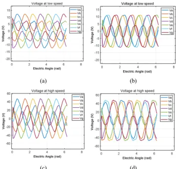
(a) (b)
(c) (d)
Fig. 5. Phase voltages in the natural frame at low speed (120rpm; Vpeak<48V) and at high speed (590rpm; Vpeak = 48V) supplied by (a)(c) only with the fundamental harmonic current (b)(d) only with third harmonic current To rq u e ( N m) To rq u e ( N m) Cu rren t(A) V o lt ag e ( V ) C urre nt (A ) V ol ta g e (V ) C u rre n t( A ) V o lt ag e ( V ) C urre nt (A ) Vol ta g e (V ) Vol ta g e (V) Vol ta g e (V)
Fig. 4 shows the optimal current characteristics compared to the back-EMF supplied by only with the fundamental
harmonic current (JRMS =5A/mm2); and only with third
harmonic current. At low speed, the optimal fundamental current has to be aligned to the fundamental back-EMF in order to have the maximal torque value. Both the 1st and the
3rd harmonic of current have the same RMS/amplitude value.
Therefore the Joule losses will be the same, but the iron losses with the 3rd harmonic will be higher. At high speed, the flux weakening operation is needed in order to extend the speed range, due to the voltage limit of the converter. In this case, the current reference is not in phase with the back-EMF, as shown in Fig. 4(c) and (d).
In Fig. 5, the phase voltages of the machine both at low and high speed are shown. The peak values of phase voltages are 48V, respecting the voltage constraint. At low speed, in order to have a maximal output torque, the current density is the main constraint. At high speed, both the current and the voltage constraints should be respected, as shown in Fig. 5(c) and (d).
C. Optimization with both the fundamental harmonic and the third harmonic of currents
One more degree of freedom of control is applied in this part, i.e. both the fundamental and the third current harmonics are optimized in order to have the maximal torque (15.13Nm before flux-weakening operation).
Fig. 6. In blue the Torque/speed characteritic in healthy mode with the respective contributions of the two ficitious machines
Fig. 6 shows the torque-speed characteristics of the machine. The total output torque is composed of the torques of the two fictitious machines (the first and third machines). Compared to the results with only fundamental current, under the same voltage and current constraints, the torque at low speed is improved by 56% and the speed range is also significantly extended from about 700 rpm to 1050 rpm.
Fig. 7 shows the optimal current and back-EMF waveforms. The same remarks can be concluded like the case with only the fundamental current, however, with the injection of the third harmonic current, the resultant current and back-EMF have similar waveforms before the flux-weakening region.
From the above analyses, it can be noted that the performance of the considered machine is improved not only at low speed (higher torque) but also at high speed (larger speed range), verifying the advantage of the more degree of
control for the 7-phase bi-harmonic machine in healthy operation.
(a) (b)
(c) (d)
Fig. 7. Performance at low (120rpm) and high speed (890rpm) with (a) (c) ia-ea; (b) (d) id-iq
V. TORQUE OPTIMIZATION IN DEGRADED MODE
A. Current reference generation in degraded mode In a drive system of a multiphase machine, the increase in the number of phases improves the fault-tolerant capability of the system. In this part, the performance of the 7-phase bi-harmonic machine with one phase open-circuited is investigated.
It is assumed that the phase A is open-circuited. In order to get a smooth torque, the method for generation of current references in [5] [6] is applied in this paper. The new current references ( , , , , , ) can be expressed as follows:
= sin( + − 21.4°) + sin(3( + − 21.4°)) = sin( + − 90°) + sin(3( + − 90°)) = sin( + − 158.6°) + sin 3( + − 158.6°) = − = − = − (9)
where and are the peak values of the first and third
harmonic currents; ′ and are adjustable phase angles
of the first and third harmonic currents; is the rotational position of the machine rotor.
The optimization problem in (7) is also used in this part in order to maximize the output torque, but with the phase A current iA equal to 0. In the following parts, the problem will be solved by using fmincon in cases with only fundamental current and both the fundamental and the third harmonic currents.
B. Optimization only with the fundamental harmonic current
The torque-speed characteristic, generated only by the primary machine (7.804Nm before flux-weakening operation),
0 200 400 600 800 1000 Speed (rpm) 2 4 6 8 10 12 14 Torque-speed Total Primary machine Third Machine X120 Y15.13 X120 Y9 X120 Y6.132 X890 Y7.652 X890 Y6.498 C u rre n t( A ) Volta g e (V ) C u rren t (A )
is shown in Fig. 8. The torque in terms of time can be seen in Fig. 13a. It can be seen that in Fig. 13(a) only the fundamental current is injected, the output torque pulsates because the primary and third machines are no longer decoupled in degraded mode.
Fig. 8. Torque curve in the full speed range control in degraded mode
(a) (b)
(c) (d)
Fig. 9. Currents at low (140rpm) and high speeds (540rpm) with (a) (c):seven phase currents; (b) (d) id-iq
(a) (b)
Fig. 10. Seven phase voltages in single-phase open-circuit fault, (a) at low speed; (b) at high speed
The maximal value of average torque at low speed is decreased by 18.8%, compared to the one in healthy mode. In order to have the same average torque, the amplitude of the
phase currents has to be increased [4]. The maximal operation speed is also slightly decreased from 700 to 650 rpm. The optimal current references at low and high speeds are presented in Fig. 9. It can be noted that the currents of the remaining healthy phases are no longer regularly distributed in terms of phase angles as shown in Fig. 9(a) and 9(c) as in healthy mode, the d-axis current is optimized and close to 0 at low speed, and the torque decreases in flux weakening region. Fig. 10 shows the voltages of the machine at low and high speeds. It is noted that the phase voltages are within their limit (48V).
C. Optimization with both the fundamental harmonic current and the third harmonic current
Fig. 11 presents the characteristics of the torque and speed using both the fundamental and the third harmonic currents (9.783Nm before flux-weakening operation). Compared to the case with only the fundamental current under the same constraints on the current and voltage, the torque at low speed is increased by 25.6%. However, it is decreased by 34.7% in comparison with healthy mode (Fig. 6).
Fig. 11. Torque-speed characteristics in the full speed range control in degraded mode
(a) (b)
(c) (d)
Fig. 12. Currents at low (140rpm) and high speed (490rpm) with (a)(c): seven phase currents; (b)(d): id-iq
100 200 300 400 500 600 700 Speed (rpm) 0 2 4 6 8 Tor que (Nm) Torque-speed Torque X140 Y7.804 X540 Y6.332 Cu rren t (A ) C u rre n t (A ) C u rren t (A ) C u rren t (A ) Vol ta g e (V) Vol tage ( V ) 100 200 300 400 500 600 Speed (rpm) 0 2 4 6 8 10 Torque-speed Total Primary machine Third Machine X140 Y9.783 X140 Y6.212 X140 Y3.57 X490 Y0.9246 X490 Y8.585
(a) (b)
Fig. 13. Torque at low speed and at high speed, (a) only with fundamental harmonic current; (b) with both fundamental and third harmonics current.
(a) (b)
Fig. 14. RMS currents density and peak phase voltages in terms of speed (a) imposing only fundamental harmonics current (b) imposing both fundamental and the third harmonic current
The optimal current references at low and high speeds are presented in Fig. 12. It can be noted that the ratio between the fundamental current and the third harmonic current changes in the flux-weakening region. In addition, the currents in d-q frames are no longer constant, which will lead to the pulsation of the output torque as shown in Fig. 13(b).
Fig. 14 shows the maximal values of the RMS current density and the peak phase voltages for the current references both at low and high speeds. It can be noted that the RMS current density with only fundamental current decreases more quickly than using both harmonics, which proves the advantage of the bi-harmonic machine, especially in flux weakening region.
VI. CONCLUSION
In this study, the specificities of a 7-phase bi-harmonic machine have been studied in both healthy and degraded modes. The characteristics of this machine are investigated through the torque optimization, and the comparisons between the case using only the fundamental current and the one with the additional third harmonic current. It is proved that not only the torque but also the speed range can be improved through the injection of the third harmonic current. It is only the first study of this special machine, the works, further studies such as the losses in the machine and the methods for reducing the pulsation of torque, should be covered in the future.
REFERENCES
[1] F. Barrero, M. J. Duran, “Recent Advances in the Design, Modeling and Control of Multiphase Machines—Part 1,” IEEE Trans. Ind. Electron., vol. 63, no. 3, pp. 449–458, Jan. 2016.
[2] K. Wang, Z. Q. Zhu, G. Ombach, “Torque Improvement of Five-Phase Surface-Mounted Permanent Magnet Machine Using Third-Order Harmonic,” IEEE Trans. Energy Convers., vol. 29, no. 3, pp.735–747, Sept. 2014.
[3] F. Scuiller, H. Zahr and E. Semail, "Maximum Reachable Torque, Power and Speed for Five-Phase SPM Machine With Low Armature
Reaction," in IEEE Transactions on Energy Conversion, vol. 31, no. 3, pp. 959-969, Sept. 2016.
[4] Fabrice Locment, Eric Semail, and Xavier Kestelyn, “Vectorial Approach-Based Control of a Seven-Phase Axial Flux Machine Designed for Fault Operation,” IEEE Transactions On Industrial Electronics, Vol. 55, No. 10, pp.3682-3691, 2008.
[5] Jen-Ren Fu, Thomas A. Lipo, “Disturbance-Free Operation of a Multiphase Current-Regulated Motor Drive with an Opened Phase,” IEEE TRANSACTIONS ON INDUSTRY APPLICATIONS, vol.30, no. 5, pp.1267–1274, Oct. 1994.
[6] Duc Tan Vu, Ngac Ky Nguyen, Eric Semail, Tiago Jose dos Santos Moraes. “Torque optimisation of seven-phase BLDC machines in normal and degraded modes with constraints on current and voltage,” The 9th International Conference on Power Electronics, Machines and Drives (PEMD 2018), July 2018
[7] Duc Tan Vu, Ngac Ky Nguyen, Eric Semail, Tiago Jose dos Santos Moraes. “Control Strategies for Non-sinusoidal Multiphase PMSM Drives in Faulty Modes under Constraints on Copper Losses and Peak Phase Voltage,” IET Electric Power Applications, 20 May 2019 [8] Dwari S, Parsa L. “Fault-tolerant control of five-phase permanent
magnet motors with trapezoidal back EMF,” IEEE Transaction on Industrial Electronics, 2011, 58(2),pp.476-485.
[9] Song Xuelei, Wen Xuhui, Cong Wei. “Research on Field-weakening Control of Multiphase Permanent Magnet Synchronous Motor,” 2011 International Conference on Electrical Machines and Systems, 2011: 1-5.
[10] Ousmane Fall; Jean Frédéric Charpentier; Ngac-Ky Nguyen; Paul Letellier, “Maximum torque per ampere control strategy of a 5-phase PM generator in healthy and faulty modes for tidal marine turbine application,” 2014 International Power Electronics and Application Conference and Exposition, Nov. 2014.
[11] X. Kestelyn and E. Semail, "A Vectorial Approach for Generation of Optimal Current References for Multiphase Permanent-Magnet Synchronous Machines in Real Time," IEEE Transactions on Industrial Electronics, vol. 58, no. 11, pp. 5057-5065, 2011.
[12] Jinlin Gong, Hussein Zahr, Eric Semail, Mohamed Trabelsi, Bassel Aslan, Franck Scuiller. “Design Considerations of Five-Phase Machine With Double p/3p Polarity,” IEEE Transactions on Energy Conversion, 2019, vol. 34, no. 1 pp.12-24.
[13] Hussein Zahr, Jinlin Gong, Eric Semail, Franck Scuiller. “Comparison of Optimized Control Strategies of a High-Speed Traction Machine with Five Phases and Bi-Harmonic Electromotive Force,” Energies, May.2016.
[14] B. Zhao, J. Gong, D. T. Vu, N. Nguyen, E. Semail, “Fault Tolerant 7-phase Hybrid Excitation Permanent Magnet Machine,” IEEE Conference on Electromagnetic Field Computation, Oct. 2018, China.
0 1 2 3 4 5 6
Electrical Angle (rad)
0 5 10 15
Torque at low and high speed At low speed At high speed To rq ue ( N m ) 100 200 300 400 500 600 700 speed (rpm) 0 1 2 3 4 5 6 0 10 20 30 40 50
RMS currents density and peak phase voltages
Jrms Vpeak C urre nt (A ) V ol ta g e (V )