Science Arts & Métiers (SAM)
is an open access repository that collects the work of Arts et Métiers Institute of
Technology researchers and makes it freely available over the web where possible.
This is an author-deposited version published in: https://sam.ensam.eu Handle ID: .http://hdl.handle.net/10985/16018
To cite this version :
Paul-Ayme TOULEMONDE, Julie DIANI, Pierre GILORMINI, Geneviève LACROIX, Nancy DESGARDIN - Roles of the Interphase Stiffness and Percolation on the Behavior of Solid Propellants Propellants, Explosives, Pyrotechnics Vol. Volume 41, Issue 6, p.Pages 978986 -2016
Any correspondence concerning this service should be sent to the repository Administrator : archiveouverte@ensam.eu
Roles of the Interphase Stiffness and Percolation on the
Behavior of Solid Propellants
Paul-Aym8 Toulemonde,*[a, b]Julie Diani,[c] Pierre Gilormini,[a]GeneviHve Lacroix,[b]and Nancy Desgardin[b]
Introduction
Composite solid propellants are elastomers highly filled with explosive particles (up to 90 wt-%) [1]. The primary function of this material is to burn and deliver a phenomen-al thrust for a very limited period. However, to ensure pre-dictable burning kinetics and proper integration into indus-trial applications, specific stress and strain at failure are tar-geted. In this respect, the use of matrix/filler bonding agents has drawn significant attention. Mixed to the matrix, the bonding agent migrates to the filler surrounding and reacts in presence of filler or matrix, the latter reaction strengthening the filler/matrix bonds. Variants of this tech-nique have been patented [2–4] for two of the main chemi-cal systems of propellants: hydroxyl-terminated polybuta-diene (HTPB) filled with ammonium perchlorate (AP) and glycidyl azide polymer (GAP) or polyethylene glycol (PEG) filled with organic particles. Looking closely at the experi-mental sections supporting these patents claims, one notes that adding some bonding agents in propellants enhances the stress at break significantly for HTPB/AP systems [2,3,5] and for systems with organic fillers [6,7]. As regards the strain at break, the presence of a bonding agent can either reduce or improve it, changes ranging from @25% to +150% for HTPB/AP propellants and from @58% to +25% for systems with organic fillers are reported by the same authors. As a result, it appears that adding a filler/matrix bonding agent in a propellant can have three distinct ben-eficial effects on the failure properties of propellants: (i) im-prove the strain at break while reducing the failure stress, (ii) improve the stress without reducing the strain at break, and (iii) improve both properties at the same time.
Varying matrix/filler interface properties has demonstrat-ed that the two first cases can be explaindemonstrat-ed by changes of
interface properties [8]. Such strengthening of the matrix/ filler interface is conventionally targeted by propellants manufacturers. However, until now, the modification of the interface properties only does not seem sufficient to ex-plain the increase of both failure stress and failure strain at the same time. That is why another phenomenon has been proposed [6] to understand the effect of bonding agents: the appearance of a matrix stiffness gradient around the particles. An increase of the initial Young modulus is ob-served for systems where bonding agents enhance both failure properties [6]. This increase could stem from a local enhancement of the matrix stiffness due to an interphase created by the bonding agent.
The presence of an interphase at the filler/matrix inter-face has been accounted for in a range of composites. AFM nano-indentation has proved to be a valuable technique to characterize both the morphology and the mechanical properties of this interphase [9,10] through the use of con-Abstract: Atomic force microscopy has provided access to
local moduli for propellants prepared with bonding agents, which create a stiffness gradient in the matrix producing a stiffer interphase surrounding the fillers. The reinforcing impact of the bonding agent appears up to some distance and interphase percolation is observed. In order to better understand the impact of bonding agents on the stress and strain at break of propellants, finite element
simula-tions are performed. Two-dimensional periodic cells con-taining randomly dispersed particles are considered, includ-ing both a cohesive zone model at the filler/matrix inter-face to account for possible debonding and an interphase that percolates or not. The influence of the interphase stiff-ness and of its percolation, on the stress and strain at break of the model propellants are evaluated through the use of a microstructure-based failure criterion.
Keywords: Propellants · Matrix/particle interface · Interphase · Mechanical behavior · Finite element analysis
[a] P.-A. Toulemonde, P. Gilormini
Laboratoire PIMM, ENSAM, CNRS, CNAM 151 Boulevard de l’Hipital
75013 Paris, France
*e-mail: paul-ayme.toulemonde@ensam.eu [b] P.-A. Toulemonde, G. Lacroix, N. Desgardin
Herakles groupe Safran Centre de Recherche du Bouchet 9 Rue Lavoisier 91710 Vert-le-Petit, France [c] J. Diani LMS, Ecole Polytechnique CNRS, Universit8 Paris-Saclay 91128 Palaiseau, France
tact mechanics [11]. It has already been used to reveal the presence of matrix/filler interphases in nanofiller [12] and microfiller [13] composites. This technique is also successful for soft materials [14]. Micro-mechanical models based on homogeneization theories [15] and FEA analysis [10,15–17] have been proposed to evaluate the influence of the char-acterized interphase on composites macroscale mechanical properties. However, these contributions focus on compo-sites with a filler volume fraction of maximum 30%, where-as propellants typically encompwhere-ass over 70% fillers volume fraction. Considering that the amount and thus the effect of an interphase are directly related to the fillers specific surface, a full new study of propellants interphase influence on the mechanical behavior is required.
In the presented contribution, original experimental evi-dence of the existence of the matrix/filler interphase is shown and key characteristics of this interphase are identi-fied. Next, 2D finite element simulations of a model materi-al represented by a periodic cell of randomly dispersed fill-ers surrounded by an interphase and embedded in a rubber matrix are presented. Finally, a qualitative study of the effects of the interphase parameters on the mechanical response and failure of the composite is conducted. It pro-vides an explanation for the possible effects of bonding agents on solid propellants.
Experimental Section
In this work, the material of interest is a ButalaneTM solid propellant such as produced by Herakles. It consists of a compound of 68 wt% of ammonium perchlorate, 20 wt% of aluminum, and 12 wt% of a modified PBHT-based matrix that were mechanically mixed and crosslinked. In order to avoid surface roughness that would hinder AFM measure-ments, smooth surfaces were ultramicrotomed at @708C with a glass/diamond knife. The AFM measurement were carried out by BiophyResearch company with a Bruker Mul-tipode 8 NanoscopeVTM machine using Peak-force QNMTM for peak-force tapping mode with scanasyst-AirTM probes with stiffness 12 Nm@1.
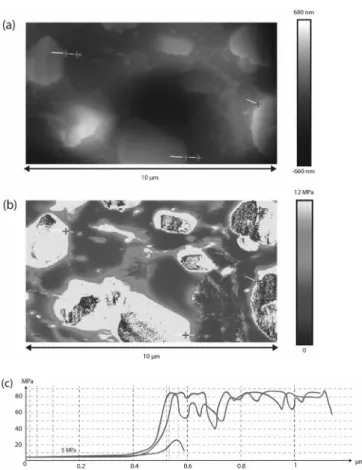
Figure 1 and Figure 2 present the local map of the re-corded Young modulus on ButalaneTMsamples. Three main phases appear on these images: (i) the matrix in dark grey, (ii) the filler particles in white, and (iii) an interphase sur-rounding the particles in light grey. In Figure 1, a particle with a radius seemingly over 30 mm and particles much smaller are observed. At this scale, it appears that the inter-phase is located around the particles and spread over the microstructure. It also appears that the interphase thickness varies from one particle to another. In some cases, the in-terphase thickness is as large as the surrounded particle radius and in other cases it is difficult to acknowledge the presence of such an interphase.
Looking closely at a couple of small particles on Fig-ure 2b, it is noted that the interphase encircles all the
parti-Figure 1. AFM observations of a portion of a large particle sur-rounded by smaller particles in ButalaneTM.
Figure 2. AFM observations of a couple of small particles: (a) topo-logical image, (b) Young modulus map, and (c) evolution of the phases stiffness along the matrix/filler interphase in three different locations.
cles to create a shell. This figure also emphasizes that con-tact points exist between these shells. Consequently, due to the high specific surface of fillers enhanced by the pres-ence of small particles into the material, the interphase may percolate through the microstructure.
Figure 2c presents the evolution of the Young modulus through matrix/filler interphases in three different locations illustrated on Figure 2a and b. The local values of the phases stiffness are thus measured and it appears that: (i) the matrix displays a Young modulus of 5 MPa, (ii) the stiff-ness of the particles is too high to be measured with the probe, and (iii) the interphase is approximately five times stiffer than the matrix.
Numerical Simulations
Experimental evidences of filler/matrix debonding have been obtained on model [5] and industrial highly filled elas-tomers [18,19]. This damaging process plays a key role in the mechanical response of these materials in unixial ten-sion [20]. Modeling efforts were conducted recently in order to understand and predict the behavior of these composites. In order to account for the filler/matrix de-bonding, a cohesive zone model was introduced to repre-sent the filler/matrix damageable interface. Micromechani-cal modeling was performed [21,22] to account for small strain behaviors with large amounts of fillers or for hypere-lastic behaviors with moderate amounts of fillers [23]. Some authors also carried out two-dimensional and three-dimensional finite element analysis. The numerical feasibili-ty of these calculations was assessed in the literature [24– 26]. Insight was gained on the effect of filler size on the mechanical behavior of composites described by a periodic lattice of particles [27] or by randomly dispersed particles [8]. The effect of the cohesive zone parameters on the me-chanical response was studied [28] and comparisons with multiscale modeling were proposed [22,29]. The presence of an interphase around the particles was also accounted for in the case of elastomers filled up to a 26% volume fraction of fillers [17].
In this work, since our interest focuses on the behavior up to failure of propellants, microstructures containing a high volume fraction of fillers are submitted to large strains. In order to detect damage localization, randomly dispersed fillers are considered. A cohesive zone model is also introduced to model the damageable filler/matrix in-terface. In order to account for the matrix stiffness gradient around particles, layers of interphase that may percolate or not are added. To reduce the complexity of the calculations, two-dimensional simulations are considered here. They will provide qualitative comparisons with experiments and will allow testing more parameters due to the reduced compu-tational cost. First, we present the microstructures, next the material and interface models, and finally the implementa-tion in the Abaqus/Standard [30] finite element code.
Microstructure
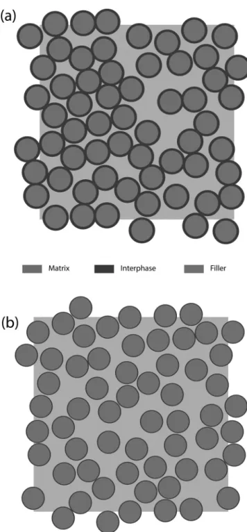
It has been demonstrated [8,27,28] that the presence of small particles mainly strengthen the matrix without notice-ably influencing the composite failure properties in the case of a propellant with a large distribution of particles size. As outlined in the Experimental Section, it also ap-pears that in the presence of an interphase, the small parti-cles promote the percolation of the interphase through the microstructure thanks to their high specific surface. For these reasons, the propellant microstructure is represented by 2D periodic cells containing distributions of 49 round particles with a single particle size representing only the large particles and a given particle surface fraction of 50%. In order to build the cell, the procedure presented in refer-ence [31] is applied. A layer of interphase of relative thick-ness e (evaluated as a fraction of the particle radius) is added around each particle. Figure 3 shows that, depend-ing on the interphase relative thickness e, overlappdepend-ing of the particle interphase may conduct to percolation of the interphase (Figure 3a) or not (Figure 3b).
Due to expected numerical behavior and failure scatter-ing, four random microstructures are created and tested for each set of parameters considered.
Material and Interface Model
The matrix is considered as quasi-incompressible and hy-perelastic and defined by its strain energy density W. In order to reduce the complexity of the numerical model a compressible neo-Hookean law is chosen (W=Em/ 6(I1@3)+Km/2(DV/V0@1)2, I1 being the first strain invariant). The matrix behavior is defined by its small strain Young modulus Em and its bulk modulus Km. It has been demon-strated that such model yields results that are consistent with propellants mechanical behaviors in term of stress-strain relation and failure properties [8].
Despite the lack of direct evidence it can be assumed safely that the interphase is also a quasi-incompressible and hyperelastic material with a gradient of stiffness through its thickness, which may be averaged to model its behavior by a compressible neo-Hookean law with a Young modulus Ei (respectively a bulk modulus Ki) larger than Em (respectively Km). The ratio H of interphase Young modulus over matrix Young modulus is therefore equal to H=Ei/Em.
The particles are regarded as rigid.
The microstructures contain two kinds of interfaces: a matrix/interphase interface and an interphase/filler inter-face. Considering the chemical similarity of the interphase/ matrix pair, this interface is regarded as perfectly bonded and thus undamageable. As explained above, debonding around filler particles is a key feature to understand the mechanical response of propellants up to failure. Therefore, a cohesive zone model is introduced at the interphase/filler interface to account for this debonding. This model repre-sents the interface through an elastic-damageable
traction-separation law. Park and Paulino [32] have reviewed multi-ple variants of the cohesive zone models that account for a range of phenomena linked to decohesion (damage be-havior, mode-mixing, in 3D especially). Among the models reviewed, a bilinear traction-separation law deriving from a potential energy independent of mode-mixing and ensur-ing the same fracture energy for any loadensur-ing path has been proposed [33]. Its simplest variant is illustrated in
Figure 4 and it is described by four parameters: K (initial “pseudo-rigidity”), G (adhesion energy), di (critical displace-ment for damage initiation), and df (critical displacement for interface failure). Only three of these parameters are in-dependent since they are related by G=Kdidf/2. Further-more, to model the fact that no debonding is allowed before the appearance of the interface damage, K is chosen as high as computation allows. Thus the chosen cohesive zone model is defined by two parameters: dfand G. Implementation
The simulations are run with Abaqus/Standard [30] using 4-node hybrid plane strain elements with reduced integra-tion. Periodic displacement boundary conditions were ap-plied to the cell. So as to ensure a ratio of 3 between the critical length df of the cohesive zone model and the ele-ment size [34], the structures were meshed with an aver-age of 300000 elements. It was verified on a periodic lattice of particles with the same microstructural and material pa-rameters that for the chosen mesh size or lower mesh sizes, the mechanical behavior is independent of the ele-ment size.
The particles radius is 0.1 mm, which is in the range of common solid propellants fillers radii for large particles [25,26,35]. The filler surface fraction is 50%, which suitably represents the volume fraction of large particles in standard solid propellants [36]. The neo-Hookean stiffness of the propellants matrix is Em=Em0=5 MPa as was evaluated in AFM measurements on Figure 2 and remains fixed, whereas the interphase behavior is given as Ei=H Emwith H=2 or 5 or 10. These values of H provide a realistic range of values according to the AFM measurements. Values of Km= 4000 MPa and Ki=H Km were chosen to obtain a quasi-in-compressible behavior. The parameters of the cohesive zone model are taken from the literature [35,37] to repre-sent a matrix/filler interface of energetic materials: K= 1000 MPa, df=0.1 mm and G=0.083 MPa mm. Relative
Figure 3. Modelled microstructures: (a) with interphase percola-tion (e=0.12), (b) without interphase percolapercola-tion (e =0.035).
Figure 4. Illustration of the chosen cohesive zone model for a posi-tive normal traction applied to the interface.
thickness e values were chosen in order to experience pos-sible percolation of the interphase through the microstruc-ture, as suggested by AFM observations. Values e=0.01 and 0.035 do not produce percolation, whereas e=0.1 and 0.12 do.
Results and Discussion
Failure Criterion
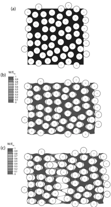
Rivlin and Thomas [38] introduced a critical elastic energy density based failure criterion for elastomers. This criterion is a mere application of fracture mechanics and is conse-quently widely used. In the presented case, the underlying principle that failure initiates in material elements with high elastic energy density is extended. Indeed, starting from a virgin microstructure (Figure 5a), early damage of the interphase/filler interface initiates homogeneously throughout the microstructure (Figure 5b). At some point, debonding localizes orthogonally to the loading direction (Figure 5c), and interphase-matrix fibrils form highlighting very high levels of elastic energy density. Therefore the strain energy based failure criterion may be equivalently defined by the appearance of the fibrillar microstructure due to debonding localization. From a practical point of view, as this localized debonding occurs, the two remaining parts of the microstructure move as rigid bodies. Experi-mental evidence attests of such a localized failure mecha-nism [39].
The elastic energy density W normalized by the small-strain Young modulus Emis a dimensionless measure of the elastic energy density and allows comparisons between simulations with different material parameters. Figure 6 il-lustrates the case, where no debonding localization occurs and the proposed failure criterion does not apply, com-pared to Figure 5c, where localization occurs. At 36% mac-roscopic strain, the no-localization microstructure does not display peaks of normalized elastic energy (Figure 6) in con-trast with the case of debonding localization (Figure 5c).
Figure 7 presents the results of four identical simulations except for the particles random layout. Very good reprodu-cibility is achieved on the behavior, while expected scatter-ing is observed on failure. Therefore, average behaviors are presented in what follows with mean values and standard deviations of the strain at break. As regards the comparison to experimental data on propellants [7,40], it appears that the shape of the stress-strain curve is well reproduced on Figure 7: first a linear portion is obtained, then the struc-ture undergoes softening and a plateau is observed. Also, the range of strain at which softening begins and the fail-ure strain are consistent. The order of magnitude of the si-mulated stress is consistent with propellants behavior at low temperature (typically @408C) and overestimates pro-pellants stress-strain response at room temperature.
Effect of the Interphase Thickness
Figure 8 shows the impact of the interphase relative thick-ness e on the mechanical behavior of the composite until failure with H=5 (when the interphase is five times stiffer than the matrix). As reference, the behavior of model mate-rials with no interphase is also represented. First, at small strain, before any interface debonding has occurred, the stiffness of the structure increases with the relative
thick-Figure 5. Evolution and ratio of the elastic energy density W nor-malized by Young modulus Emfor a microstructure without
inter-phase submitted to uniaxial tension. (a) Initial microstructure, (b) early damage (20% macroscopic strain), and (c) further damage evolution with the appearance of matrix fibrils (36% macroscopic strain) (Em=Em0).
ness e, the interphase being stiffer than the matrix. As for fracture, two cases can be distinguished. When the inter-phase is thin, the composite shows similar behavior until break as the reference presenting no interphase and a Young modulus Em=Em0. When the interphase is thick, no debonding localization occurs. In this case, the composites sustain larger strain and stress at break and display a similar evolution to the one of the reference material without in-terphase and a Young modulus Em=H.Em0. From a micro-structural point of view, it is to notice that, the interphase percolates for the second group only. Thus, a path to trans-mit the load through the microstructure exists and relieves the softer matrix. Consequently the structure is stiffer and behaves very similarly to a composite with a stiff matrix without interphase.
Hence, for H=5, the presence of a stiff interphase has a significant impact when the interphase percolates and none when it does not percolate.
According to these results, the presence of a percolating interphase enhances both stress and strain at break of the composite, which is consistent with experimental results on HTPB/AP and organic filler systems [2,6] reported in the In-troduction. Introducing an interphase in the simulated mi-crostructures also leads to an increase in the initial Young modulus as observed experimentally for organic filler sys-tems [6]. However, stress (respectively strain) at break of the numerical results for non-percolating microstructure does not show a marked increase (respectively decrease) as could be expected from experimental results. This differ-ence could stem from the fact that on the one hand, in the calculations, the presence of a bonding agent was solely accounted for through the introduction of an interphase but no modification of the filler/matrix properties was im-plemented. Whereas, on the other hand, bonding agent are designed to reinforce the matrix/filler bond [41]. Yet, it has been demonstrated [8,28] that a change of the critical strength or of the debonding energy of the cohesive zone, which both represent a modification of the interface, can produce such an increase in the stress at break.
Effect of the Interphase Stiffness
Figure 9 illustrates the influence of the H ratio on the bene-ficial effect of interphase percolation on the failure of the composite. Two interphase relative thicknesses with (e= 0.12) and without (e=0.035) percolation were tested, each with two values of the ratio H, 2 and 10, compared to the reference case H=5. For a thin interphase (Figure 9a), the
Figure 6. Microstructure and normalized elastic energy density W at 36% macroscopic strain for a microstructure without interphase when debonding localization does not appear due to a high matrix stiffness (Em=5 Em0).
Figure 7. Uniaxial tension responses of four microstructures of identical constitutive parameters and differing by the particles layout only.
Figure 8. Effect of the interphase thickness on the uniaxial behav-ior of composites with interphase stiffness characterized by H=5. The case e =0 (respectively e=1) represents a microstructure without interphase and Em=Em0(respectively Em=H Em0).
stiffer the interphase, the stiffer the composite and the larger its stress at failure. As regards the strain at failure, at low values of ratio H, it is similar to the reference case Em= Em0: the failure remains unaffected by the presence of the interphase. At a higher value of ratio H the strain at break increases significantly.
For a percolated interphase (Figure 9b), the stiffer the in-terphase, the stiffer the composite at small strain. Concern-ing the failure properties, two cases appear: (i) for stiff in-terphases (H=5 and 10) a 50% increase of the stress and strain at break is achieved, whereas (ii) for a soft interphase (H=2) no noticeable influence on the failure behavior is observed. Note that for this relative thickness e and a suffi-ciently high value of the H ratio, the mechanisms are similar to the one observed for the reference case without inter-phase and high matrix stiffness.
According to these results, the presence of a percolating interphase is not always sufficient to achieve an improve-ment of both stress and strain at break, a sufficiently stiff interphase in comparison to the matrix is also necessary. Besides, a non-percolated interphase can also yield im-provement of the failure strain but not of the failure stress. Very local measurements such as AFM peak force are re-quired to check these conditions and they cannot be easily predicted when formulating the material. For these reasons the presence of an interphase can have a range of effects on the stress and strain at break – improving both or not affecting them – that cannot be interpreted without local measurements. This could explain the discrepant experi-mental results found in the literature and the difficulties ex-perienced to consistently interpret them.
Conclusions
AFM observations with Young modulus measurements at the microscale were conducted. The presence of an inter-phase between matrix and fillers in industrial solid propel-lants was experimentally observed and its morphology and Young modulus were evaluated. An interesting feature of this interphase is to possibly percolate through the matrix. So as to understand the effect of this interphase on the mechanical behavior, a propellant-like highly filled elasto-mer was modeled by 2D periodic cells containing randomly dispersed rigid particles coated by an elastomer interphase and embedded in an elastomer matrix. Debonding of the interphase/filler interface was permitted through the use of a cohesive zone model. A failure criterion was proposed as the appearance of a fibrillar microstructure and two constit-utive parameters of the interphase were varied: the relative thickness of the interphase e and the ratio H of interphase stiffness over matrix stiffness. Changing e revealed the sig-nificant impact of the percolation of the interphase by re-ducing the localization of filler/matrix debonding and therefore increasing the stress and strain at failure.
Nonetheless, as variations of H have shown, conditions on the interphase stiffness are preponderant. At low inter-phase stiffness, there is no room for improvement of failure properties. At medium interphase stiffness, the interphase percolation is a necessary condition to obtain an increase of both strain and stress at failure. At high interphase stiff-ness, the failure strain can be improved without percolation but it is required to enhance the failure stress.
According to these mechanisms, adding bonding agents to propellants formulations can have a favorable impact on both stress and strain at failure in two cases: for a stiff per-colating interphase, and in a more limited respect, for a very stiff interphase. In the other cases, no significant impact is observed if it is assumed that the interface prop-erties are unchanged. These conditions on the interphase are very local properties that are difficult to predict precise-ly a priori. This can explain the discrepant results obtained
Figure 9. Comparison of the uniaxial behaviors of microstructures for different rigidity ratios H with fixed interphase relative thick-ness: (a) e=0.035, (b) e=0.12. In the cases Em=Em0(respectively
Em=5 Em0), there is no interphase but a matrix with stiffness Em0
by authors when evaluating the effect of a given bonding agent on the mechanical response.
Acknowledgments
The authors wish to thank DGA for its financial support.
References
[1] A. Davenas in: Technologie des Propergols Solides, Masson, Paris, 1988.
[2] H. Allen, Composite Solid Propellant with Additive to Improve the Mechanical Properties Thereof, US Patent 3745074, The United States of America as represented by the Secretary of the Army, Decatur, AL, USA, 1973.
[3] J. P. Consaga, Bonding Agent for Composite Propellants, US Patent 4944815, The United States of America as represented by the Secretary of the Navy, Washington, D.C., USA, 1980. [4] C. S. Kim, Filler Reinforcement of Polyurethane Binder Using
a Neutral Polymeric Bonding Agent, US Patent 4915755, Sacra-mento, CA, USA, 1990.
[5] A. E. Oberth, R. S. Bruenner, Tear Phenomena around Solid In-clusions in Castable Elastomers, Trans. Soc. Rheol. 1965, 9, 165–186.
[6] C. S. Kim, P. N. Noble, C. H. Zoun, D. Tarrant, A. Gao, The Mech-anism of Filler Reinforcement from Addition of Neutral Poly-meric Bonding Agents to Energetic Polar Propellants, Propel-lants Explos. Pyrotech. 1992, 17, 51–58.
[7] E. Landsem, T. L. Jensen, F. K. Hansen, E. Unneberg, T. E. Kris-tensen, Neutral Polymeric Bonding Agents (NPBA) and Their Use in Smokeless Composite Rocket Propellants Based on HMX-GAP-BuNENA, Propellants Explos. Pyrotech. 2012, 37, 581–591.
[8] P.-A. Toulemonde, J. Diani, P. Gilormini, N. Desgardin, On the Account of a Cohesive Interface for Modeling the Behavior Until Break of Highly Filled Elastomers, Mech. Mater. 2016, 93, 124–133.
[9] S.-L. Gao, E. Mader, Characterisation of Interphase Nanoscale Property Variations in Glass Fibre Reinforced Polypropylene and Epoxy Resin Composites, Composites Part A 2002, 33, 559–576.
[10] S.-H. Lee, S. Wang, G. M. Pharr, H. Xu, Evaluation of Interphase Properties in a Cellulose Fiber-Reinforced Polypropylene posite by Nanoindentation and Finite Element Analysis, Com-posites Part A 2007, 38, 1517–1524.
[11] B. V. Derjaguin, V. M. Muller, Yu. P. Toporov, Effect of Contact Deformations on the Adhesion of Particles, J. Colloid Interface Sci. 1975, 53, 314–326.
[12] A. Pakzad, J. Simonsen, R. S. Yassar, Gradient of Nanomechani-cal Properties in the Interphase of Cellulose Nanocrystal Com-posites, Compos. Sci. Technol. 2012, 72, 314–319.
[13] Y. Wang, T. H. Hahn, AFM Characterization of the Interfacial Properties of Carbon Fiber Reinforced Polymer Composites Subjected to Hygrothermal Treatments, Compos. Sci. Technol. 2007, 67, 92–101.
[14] T. J. Young, M. A. Monclus, T. L. Burnett, W. R. Broughton, S. L. Ogin, P. A. Smith, The Use of the PeakForce Quantitative Nanomechanical Mapping AFM-Based Method for High-Reso-lution Young’s Modulus Measurement of Polymers, Meas. Sci. Technol. 2011, 22, 125703.
[15] F. T. Fisher, L. C. Brinson, Viscoelastic Interphases in Polymer@ Matrix Composites: Theoretical Models and Finite-Element Analysis, Compos. Sci. Technol. 2001, 61, 731–748.
[16] W. Wang, K. Sadeghipour, G. Baran, Finite Element Analysis of the Effect of an Interphase on Toughening of a Particle Rein-forced Polymer Composite, Composites Part A 2008, 39, 956– 964.
[17] D. W. Spring, G. H. Paulino, Computational Homogenization of the Debonding of Particle Reinforced Composites: The Role of Interphases in Interfaces, Comput. Mater. Sci. 2015, 109, 209– 224.
[18] C. D. Bencher, R. H. Dauskardt, R. O. Ritchie, Microstructural Damage and Fracture Processes in a Composite Solid Rocket Propellant, J. Spacecrafts Rockets 1995, 32, 328–334.
[19] Z. J. Tao, S. D. Ping, Z. Mei, Z. P. Cheng, 12th International Sym-posium on Multiscale, Multifunctional and Functionally Graded Materials, Beijing, P. R. China, October 22–26, 2013.
[20] L. A. Vratsanos, R. J. Farris, A Predictive Model for the Mechani-cal Behavior of Particulate Composites. Part II: Comparison of Model Predictions to Literature Data, Polym. Eng. Sci. 1993, 33, 1466–1474.
[21] H. Tan, C. Liu, Y. Huang, P. H. Geubelle, The Cohesive Law for the Particle/Matrix Interfaces in High Explosives, J. Mech. Phys. Solids 2005, 53,1892–1917.
[22] H. M. Inglis, P. H. Geubelle, K. Matous, H. Tan, Y. Huang, Cohe-sive Modeling of Dewetting in Particulate Composites: Micro-mechanics vs. Multiscale Finite Element Analysis, Mech. Mater. 2007, 39, 580–595.
[23] L. Brassart, H. M. Inglis, L. Delannay, I. Doghri, P. H. Geubelle, An Extended Mori-Tanaka Homogenization Scheme for Finite Strain Modeling of Debonding in Particle-Reinforced Elasto-mers, Comput. Mater. Sci. 2009, 45, 611–616.
[24] J. Segurado, J. Llorca, A New Three-Dimensional Interface Finite Element to Simulate Fracture in Composites, Int. J. Solid Struct. 2004, 41, 2977–2993.
[25] K. Matous, P. H. Geubelle, Finite Element Formulation for Mod-eling Particle Debonding in Reinforced Elastomers Subjected to Finite Deformations, Comput. Methods Appl. Mech. Eng. 2006, 196, 620–633.
[26] K. Matous, H. M. Inglis, X. Gu, D. Rypl, T. L. Jackson, P. H. Geu-belle, Multiscale Modeling of Solid Propellants: From Particle Packing to Failure, Compos. Sci. Technol. 2007, 67, 1694–1708. [27] X. A. Zhong, W. G. Knauss, Analysis of Interfacial Failure in Par-ticle-Filled Elastomers, J. Eng. Mater. Technol. 1997, 119, 198– 204.
[28] J. Moraleda, J. Segurado, J. Llorca, Effect of Interface Fracture on Tensile Deformation of Fiber-Reinforced Elastomers, Int. J. Solid Struct. 2009, 46, 4287–4297.
[29] D. Ngo, K. Park, G. H. Paulino, Y. Huang, On the Constitutive Relation of Materials with Microstructure Using a Potential-Based Cohesive Model for Interface Interaction, Eng. Fract. Mech. 2010, 77, 1153–1174.
[30] Abaqus/Standard, Dassault SystHmes Simulia Corporation, Providence, RI, USA, 2010.
[31] S. Torquato, Random Heterogeneous Materials, Springer, Heidel-berg, 2002.
[32] S. E. Leon, G. H. Paulino, A. Pereira, I. F. M. Menezes, E. N. Lages, K. Park, A Unified Library of Nonlinear Solution Schemes, Appl. Mech. Rev. 2011, 64, 040803-1-26.
[33] V. Tvergaard, J. W. Hutchinson, The Influence of Plasticity on Mixed Mode Interface Toughness, J. Mech. Phys. Solids 1993, 41, 1119–1135.
[34] A. Turon, C. G. Davila, P. P. Camanho, J. Costa, An Engineering Solution for Mesh Size Effects in the Simulation of
Delamina-tion Using Cohesive Zone Models, Eng. Fract. Mech. 2007, 74, 1665–1682.
[35] H. Tan, Y. Huang, C. Liu, G. Ravichandran, H. M. Inglis, P. H. Geubelle, The Uniaxial Tension of Particulate Composite Mate-rials with Nonlinear Interface Debonding, Int. J. Solid Struct. 2007, 44,1809–1822.
[36] A. Azoug, Microm8canismes et Comportement Macroscopique d’un PlastomHre Fortement Charg8, PhD Thesis, Ecole Polytech-nique, Paris, France, 2010.
[37] W. Yan-Qing, H. Feng-Lei, A Micromechanical Model for Pre-dicting Combined Damage of Particles and Interface Debond-ing in PBX Explosives, Mech. Mater. 2009, 41, 27–47.
[38] R. S. Rivlin, A. G. Thomas, Rupture of Rubber. I. Characteristic Energy for Tearing, J. Polym. Sci. 1953, 10, 291–318.
[39] C. T. Liu, L. M. Klynn, J. D. Thompson, in Monitoring Microstruc-tural Evolution and Crack Formation in a Solid Propellant under
Incremental Strain Condition using Digital Radiography X-ray Techniques, Technical Report, Defense Technical Information Center, ADA423473, Fort Belvoir, VA, USA, 2004.
[40] S. Ozupek, E. B. Becker, Constitutive Modelling of High-Elonga-tion Solid Propellants, J. Eng. Mater. Technol. 1992, 114, 111– 115.
[41] K. Hori, A. Iwama, T. Fukuda, On the Adhesion Between Hy-droxyl-Terminated Polybutadiene Fuel-Binder and Ammonium Perchlorate. Performance of Bonding Agents, Propellants Explos. Pyrotech. 1985, 10, 176–180.
Received: March 17, 2016 Published online: August 25, 2016

![Band offsets of n-type electron-selective contacts on cuprous oxide (Cu[subscript 2]O) for photovoltaics](data:image/gif;base64,R0lGODlhAQABAIAAAP///wAAACH5BAEAAAAALAAAAAABAAEAAAICRAEAOw==)