Science Arts & Métiers (SAM)
is an open access repository that collects the work of Arts et Métiers Institute of
Technology researchers and makes it freely available over the web where possible.
This is an author-deposited version published in:
https://sam.ensam.eu
Handle ID: .
http://hdl.handle.net/10985/7916
To cite this version :
David LUNA, Jean-Pierre NADEAU, Yves JANNOT - Solar timber kilns: State of the art and
foreseeable developments Renewable and sustainable energy reviews Vol. 13, p.14461455
-2009
Any correspondence concerning this service should be sent to the repository
Solar timber kilns: State of the art and foreseeable developments
D. Luna
a,*
, J.-P. Nadeau
a, Y. Jannot
baTREFLE CNRS UMR 8508 Esplanade des Arts et Me´tiers 33405 Talence, France b
LEMTA UMR CNRS 7563, 2, Avenue de la Foˆret de Haye 54504 Vandoeuvre, France
Contents
1. Introduction . . . 1447
2. Analysis methodology . . . 1447
2.1. Organic approach . . . 1447
2.2. Laws of evolution for technological systems. . . 1447
3. State of the art of the ‘‘solar kiln’’ system . . . 1447
3.1. Organic approach . . . 1448
3.2. Global analysis of the state of the art . . . 1448
3.3. Solar kiln with integrated collector (arrangement 1) . . . 1448
3.4. Solar kiln with lateral semi-integrated collector (arrangement 2). . . 1449
3.5. Solar kiln with storage (arrangement 3) . . . 1449
3.6. Development trends in solar kilns for drying timber . . . 1450
4. State of evolution of the heating unit . . . 1450
4.1. Organic approach . . . 1450
4.2. Evolution of the selective unit . . . 1451
4.3. Evolution of the absorber. . . 1451
4.3.1. Energy transformation. . . 1451
4.3.2. Energy transmission . . . 1452
4.3.3. Energy transfer to the heat-transfer fluid. . . 1452
4.4. Evolution of the insulation unit. . . 1452
4.5. Evolution trends . . . 1452 5. Proposed evolution . . . 1453 6. Conclusion . . . 1454 References . . . 1454 Keywords: Drying Timber Solar kiln Collector Design A B S T R A C T
Analysis of the evolution in solar heated drying kilns in recent decades shows that there have been a series of modifications to optimize their thermal and drying efficiency.
Using an analysis method based on product design, we report on existing solar timber kilns. The different dryers and their component units are studied, developments are noted, focusing on changing trends in technological systems. As a result of this analysis we suggest some future adaptations.
* Corresponding author. Tel.: +33 5 56 84 54 16; fax: +33 5 56 84 54 01. E-mail address:[email protected](D. Luna).
1. Introduction
Since the 1960s, several types of solar kiln have been studied and improved on, and we find kilns ranging from very simple systems, with only a small capacity, to automated dryers with an integrated energy storage system.
There are many works which provide a classification of solar kilns [1], dividing them into solar kilns of the agricultural greenhouse type and solar kilns with an external collector. The aeraulics of the dryer consist of natural convection or forced convection.
We suggest a classification system for timber kilns, according to the arrangement of the main components (collector and timber stack), and we observe three typical groups.
In order to analyze the kilns, describe their respective means of functioning and draw conclusions as to foreseeable changes that might be introduced, we first define a methodology. An organic approach is used to demonstrate each of the units in the system and their relationship with the environment. The following elements can be found: drying unit, heating unit, storage unit and finally a control unit. Interaction components link these units together.
Analysis of the changes observed was according to the eight laws of technological system evolution from the TRIZ theory[2]. This analysis was carried out on the system as a whole but also on the heating unit (solar collector). Lastly, a new concept is suggested which brings together the most interesting arrangement and the most efficient and economic heating unit which incorporates the changes that will improve drying quality. This kiln has been designed, modeled, simulated and optimized in the context of studies for a doctoral thesis.
2. Analysis methodology 2.1. Organic approach
Analysis of the ‘‘solar timber kiln’’ system consists of exploring the different existing designs, both on the market and described in the literature. Our description of the system is based on an approach used in the structure analysis of a design problem, the organic approach[3].
Using the organic approach, a system can be decomposed structurally. It is represented using a tool from functional analysis, the technical organigram (TO) [4], which produces a technical description of the system to be designed, broken down into functional units. In order to take into consideration influences of the system’s environment, the TO is extended to the surroundings in the extended Technical Organigram (eTO) [5]. The units are linked together by interaction components, which transmit flows of energy, matter and information. These may be manufactured components (bolts, screws, rivets, pipes, cables, electrical wires, connectors, etc.) or linking components (weld, glue, etc.). Observation of technical systems shows that, over time, they become standardized (by moving down through the system levels of the TO), they become fewer in number then they disappear (the units combine together in a mass).
2.2. Laws of evolution for technological systems
The degree of development of any system is analyzed according to two major lines of change, first, the evolution of the environment surrounding the product (external environments) and second, the evolution of its components.
To describe the findings observed in the case of solar timber kilns, we used the eight laws or trends of evolution for
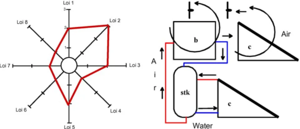
technological systems derived from the TRIZ theory[2]. Each kiln was given a score for each law on an analysis grid and this information was represented on a radar plot which determines the degree of evolution of the system. These laws are as follows:
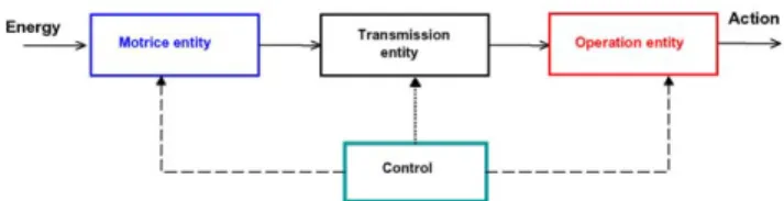
Law 1. Completeness of parts Law 2. Energy conductivity Law 3. Coordination of rhythms Law 4. Increase in level of improvement Law 5. Non-uniform development of entities Law 6. Transition towards a supersystem Law 7. Transition from macro-level to micro-level Law 8. Increase in dynamism and level of controllability In order to carry out the incriminated action, energy must be transformed, transmitted and used. Law 1 defines the existence of four entities within the system (Fig. 1), each of which must participate minimally in the carrying out of the action.
It is sometimes difficult to express this law; Nadeau and Pailhes
[5]recommend following the functional flow associated with the carrying out of the action and using a functional block diagram (FBD)[3]. With the FBD, relations between the functions and the components of a system can be demonstrated[4].
According to law 2, the system must allow the free passage of energy between all entities as the action is carried out (energy may be transmitted with or without contact). Energy transmission should be as efficient as possible and there must be maximum control of any heat loss in the system and also the correct energy use. Law 3 states that frequencies, vibrations, periodicity between all entities of the system must be coherent as the action is carried out.
We now analyze the level of improvement in the system. Law 4 states that all systems at first have a tendency to evolve, increasing in complexity in order to increase performance and improve its functioning. Next, they tend to become more simplified, while retaining their functioning level and operating safety.
Each entity evolves in its own way and an entity which reaches its point of decline blocks the evolution of the entire system. Law 5 concerns this non-uniform development between entities which causes technical and physical contradictions to be generated. For a system to be able to evolve correctly there are two solutions that we can envisage: the elimination of contradictions and the uniform development of the entities concerned.
Laws 6 and 7 define the possibilities of moving towards the lower (micro-level) or higher levels of a system, as shown in the eTO (in association with the external surroundings). The environ-ment of the product (external surroundings) influences possible changes. The evolution of these surroundings depends on functional criteria, on technological obstacles that must be overcome, on economic, sociological and even political constraints. The last law (law 8) concerns the increased dynamism and level of controllability: entities in the system evolve from static to dynamic behaviors in order to increase their controllability, thus uncontrollable entities become controllable and compatible one with another.
Fig. 1. Entities present in a system according to the law of completeness of parts (law 1).
3. State of the art of the ‘‘solar kiln’’ system 3.1. Organic approach
Simpson [6] has studied solar timber kilns and suggests a
classification according to the level of complexity of their control system. The simplest is an insulated kiln like an agricultural greenhouse, with natural air circulation. The next group consists of agricultural greenhouses used in small or medium-sized busi-nesses. Semi-automatic dryers to improve thermal efficiency make up the third group. Lastly, the fourth and most complex group consists of automated solar kilns equipped with systems such as thermostats, humidostats, dampers to control air flows, reversible ventilators and a complementary energy source. This last group requires considerable investment.
To analyze these solar drying systems, and in accordance with the method described, we identify the arrangement of the main components of a solar kiln on level 1 of the extended technical organigram inFig. 2.
We define a solar kiln as a system consisting of two main units: a drying unit (dryer chamber, b) and a heating unit (solar collector, c). There may also be an energy storage tank (stk) and a control unit. During the functioning of a system, functional flows circulate between the units; these are flows of energy, matter and information. In the case of a kiln, this is the flow of drying air (energy and matter). The information flow is linked with the kiln’s control parameters.
In order to ensure the flow of the drying air, the units must interact. We therefore identify the interaction components: air ducts (free and forced convection) and fans (forced convection). The functioning of the system is very much influenced by the surroundings, such as the position of the sun, variations in temperature and humidity relative to the air outside (meteorol-ogy) and also the availability of electrical power to operate the fans.
The respective positions of the units define the different arrangements possible and to represent the kiln we use the icons fromFig. 2.
3.2. Global analysis of the state of the art
As a result of our research, we observed various changes in the units of the ‘‘solar kiln’’ system.
Concerning the heating unit, the most remarkable improvement was the efficiency of the collectors. Later, we present a specific analysis of changes observed in solar collectors in Section4.
Concerning the drying unit, the main points to note are: - reduction in heat loss (insulated walls). The use of primitive
building materials with no insulation (plastic sheet, wood) has
evolved towards brick and well-insulated concrete [7,8]. In particular, the Australian company Solar Dryers Australia, produces kilns with aluminum alloy-clad walls with internal insulation,
- optimization of the aeraulics (reduced losses of charge and speeds have become uniform) thanks to the position of the fan interaction component during aspiration,
- use of automatic control devices inside the chamber for humidity, air change and the solar collector by-pass when there is insufficient sunshine[7].
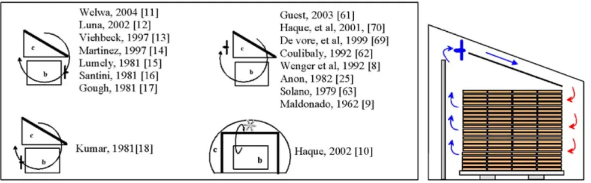
Three typical arrangements can be seen, and these have been classified according to the arrangement of the main components of the kiln, i.e. the drying unit (pile of timber), the heating unit and the storage unit, when this is present.Fig. 3summarizes the main arrangements that are found.
The three groups in the solar kiln classification demonstrate the lengths to which researchers and designers of solar timber kilns have gone to try and find a self-sufficient solar kiln system which can function both day and night.
Arrangement 1 is the one which first inspired the development of the solar kiln[9]. This arrangement was later taken up by many constructors but overall it has never evolved much. However, as we shall see, the development suggested by the Australians who have integrated the collector into the drying chamber represents a very interesting solution[10].
We observe that the group of kilns that has been studied most is the one that corresponds to arrangement 2, as separating the units makes the solar kilns more flexible.
The third group consists of kilns that include an energy-storage unit. There are two kilns in this group: the first one that we found used water as the heat-transfer fluid for storage, and the second incorporated a bed of stones placed below the kiln, heated directly by the air in the chamber.
From the positions of the interaction components it is possible to differentiate the kilns and demonstrate changes that have occurred.
Fig. 2. Technical organigram (eTO) of the kiln.
Fig. 3. Classification of solar kilns according to arrangement of main units. 1448
3.3. Solar kiln with integrated collector (arrangement 1)
The solar kiln with the integrated collector is a system in which the units are all part of one and the same construction (Fig. 4), where the solar collector is always placed above the stack to be dried or directly on the chamber roof. This is the oldest[9], but also the one that has been used most often over the years as it is
compact and easy to build [8–18,25,61–63,69,70]. Apart from
improvements in the collector, the main development concerns the positioning of the fans and the direction of aspiration, thus we have two typical sub-groups:
- one where air is drawn in from the collector and discharged towards the stack (good air distribution in the collector)[11–18], - one where air is drawn in from the stack and discharged towards
the collector (good air distribution in the stack)[18].
In order to recover as much solar energy as possible by tracking
the sun throughout the day (favorable latitude), Haque [10]
suggests a solar collector that surrounds the drying chamber. The drying chamber has two roles, first, it functions as the transparent cover of the absorber and second, a layer of air between the inside and outside walls reduces heat loss from the dryer.
3.4. Solar kiln with lateral semi-integrated collector (arrangement 2) In the semi-integrated kiln the units are separate, linked only by the interaction components, the air ducts and the fan (Fig. 5). Several authors have suggested this arrangement. At first, of course, kilns used natural air circulation [19], but subsequent changes have introduced a fan to increase drying efficiency.
The positioning of the fan, the interaction component, differs in
each model. For example, some authors [20,21,64]put the fan
between the chamber and the collector (lower part), others put it above the timber stack[65–68]. To improve evacuation, one idea is to place the fan between two timber stacks[22]. The aim of the different innovations observed is:
- to improve outflow[7,64],
- to make it possible to by-pass the collector at night[7,19,22,64]. Placing the fan before or after circulation through the timber stack, depending on the construction of the kiln, ensures that there is good air circulation in the stack. Traditionally, it is more efficient to place it in the after position, drawing air from the system we want to control, and moreover, spending on electricity is reduced. Building independent drying and heating units represents an advantage for the evolution of each as any changes made to one do not affect the development of the other.
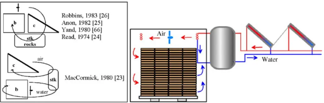
3.5. Solar kiln with storage (arrangement 3)
This arrangement represents a modification to arrangement 2 by incorporating energy storage. We find two variations for this type of arrangement.
The first kiln has a battery of liquid-based collectors (Fig. 6)
[23]. These collectors use the ‘‘pipe’’ interaction component to link them to a water storage unit; this water then warms the air by means of an exchanger in the drying unit.
The other solution involves a solar kiln with a bed of stones under the timber stack. Air flows from the collector across the stones and then passes into the timber stack. Obviously, the energy supplied to the wood during the daytime will be determined by the accumulation capacity of the bed of stones. This solution has not been used much due to the somewhat cumbersome nature of the bed of stones[24–26,65,66].
Fig. 4. Solar kilns with integrated collector (arrangement 1).
By storing energy it is possible to maintain a temperature that is virtually uniform or to control the temperature in the chamber. This will have direct consequences on the quality of the product as once the heating can be made constant then the system can be controlled.
Using liquid-based collectors to store the energy and to heat the chamber affects the efficiency of the system as two water–air transfers are required (both during the daytime and at night), between the collector and the storage tank and between the storage tank and the chamber.
Initial investment is considerable (cost of producing the storage tank and cost of the land). This system should therefore be judged according to different criteria, in particular the cost of ownership and of improving the quality of the products.
3.6. Development trends in solar kilns for drying timber
We use the development trends described to produce an analysis of the existing situation and to imagine future developments.
To carry out the action ‘‘drying the timber’’, solar energy is transformed, transmitted and used in the system. To this end, according to the law of completeness of parts (law 1) we identify a motor entity (the collector in the heating unit transforms energy from solar radiation into heat energy in the form of hot air), a transmission entity (ducts transmit the hot air), an operator (the drying chamber where the hot air dries the timber) and a control entity (Fig. 7).
Quality control of the product is now carried out by monitoring humidity and controlling the flow of drying air via control variables (VP). The different entities then improve their efficiency.
In accordance with the next two laws (law 2: energy conductivity and law 3: coordination of rhythms), we note that insulation in the kilns has got better and better. The insulating materials derive from resources available in the local environment. The notion of rhythm can be found in arrangement 3 where the alternating day/night rhythm is taken into account. The use of strategically placed fans which in most cases draw in air in front of the timber stacks serves a similar purpose.
Next, the degree of improvement as defined by law 4. The appearance of controls produces aeraulics that are more complex to manage and the integration of storage. The quality of the product in the chamber is monitored by the humidity control and the aeraulics control.
Concerning law 5, with arrangement 1 the drying chamber dictates the dimensions of the solar collector, while switching to arrangement 2 allows for dimensions that are adapted to energy needs and the volume of wood to be dried.
Laws 6 and 7 define the possibilities of shifting to a micro-level and associating the system with the surroundings. We observe that with a detailed knowledge of the materials and the associated transfer phenomena the kilns can be better run, automatic controls are possible and thus control of the drying process and the quality of the dried product are improved. Developments in arrangement 1
[10]mean that the kiln is integrated into its environment and thus reduces the surface area required; this integration solution follows along the lines of law 7.
The last law (law 8) concerns the increase in dynamism and in the level of controllability: the flexibility of arrangement 2, making nocturnal energy available by integrating separate heat storage, gives possibilities of dynamic adaptation, and the presence of the storage unit, vents and adjustable fans means that the drying ducts can be monitored and controlled.
4. State of evolution of the heating unit 4.1. Organic approach
According to the global system (eTO N1,Fig. 1), the heating unit at level 2 is a flat-plate solar collector in the kilns. This is a specific type of heat exchanger which transforms solar radiation energy into heat [27]. The design of the collector will depend on the amount of energy required by the system to be heated and on the heat-transfer fluid available, thus we move from simple flat collectors to evacuated collectors and solar concentrators. Solar collectors generally consist of: a transparent cover, a blackened metal absorber, one or several pipes and insulation. To describe this system, we use the extended technical organigram showing level 2 (eTO N2) inFig. 8 [3].
In the case of collectors, we found no interaction components between the system units. At the interface with the absorber, the fluid recovers energy by convection. This energy is transmitted directly to the operator or stored.
The heat-transfer fluid is an environment that is external to the system, it may be chosen according to how much heat is needed. Several fluids are used, such as air, water and thermal fluids (sensible heat) or substances which change phase (latent heat). The heat recovered from the absorber will depend on the physical properties of the fluid. By using phase change fluids it is possible to improve transfers at the absorber/fluid interface, and thus have better energy recovery.
The collectors of sensible heat that are normally used can be classified into two groups: air-type collectors and liquid-type collectors[28].
According to several authors, the design of solar collectors enables us to classify them into different groups, according to the
Fig. 6. Solar kiln with storage (arrangement 3).
Fig. 7. All the parts applied to the solar kiln. 1450
arrangement of the components [29,30] or to the presence or absence of the transparent cover[31,32].
The first collectors studied consisted of a metal absorber, insulating material[34]and an optional transparent cover. The development that followed made it essential that a single or double transparent cover be used above the absorber in order to reduce heat loss at the front[33].
In our analysis, we study three groups of solar collectors: air-based collectors, liquid-air-based collectors and evacuated tube collectors. We define developments they have undergone accord-ing to the laws of evolution for technological systems.
Air-based solar collectors are usually built to be used directly for drying. The air is heated directly as it passes through the collector.
The group of liquid-based solar collectors, intended mainly for heating domestic water, has rapidly improved in efficiency. This is because special materials are used thus improving the optical properties of the components (transparent cover and absorber).
Lastly, the third group concerns a special type of collector, the evacuated tube solar collector. This generally consists of a transparent glass tube, a selective absorber and one or several pipes. The absorber is placed inside the tube then the air is removed from the tube or it is filled with an inert gas; in this way, losses by convection between the absorber and the glass wall are minimized[35].
The law of completeness of parts was used to structure our analysis of the action ‘‘heat a fluid by solar energy’’, the main function of a solar collector. The entities that make up this system can be seen inFig. 9. A motor entity represented by the selective unit (the transparent cover, the confined air or the vacuum between the cover and the absorber, the surface of the absorber); a transmission entity (the absorber) and an operator entity (the absorber/heat-transfer fluid interface). The control unit, if it exists, enables the collector to be turned in order to track the sun.
The three groups differ in their motor entity (selective unit) and operation entity (absorber/heat-transfer fluid interface) (Fig. 10). 4.2. Evolution of the selective unit
An efficient cover should minimize absorption and reflection from solar radiation so that as much energy as possible reaches the absorber.
Various materials (glass, plastic) have been used to produce transparent covers. The first covers made out of plastic brought costs down, but also reduced the lifetime of the product. Next, plastic covers reinforced with fiber glass lengthened the lifetime
but without improving the performance of the collector. Lastly, glass was used which combined efficiency and a longer life for the cover. Heat losses were reduced still further by using a double layer of glass, but this proved to be no longer necessary after the appearance of special types of glass (white low-iron anti-reflection glass) which reduce glare and increase solar energy transmission
[35,36].
The second element in the selective unit is the air confined between the cover and the absorber. The effects of convection should be limited to minimize losses from the front. Innovations have emerged, replacing air by an inert gas or a vacuum (only for liquid-based collectors due to the mechanical properties of the tubes).
4.3. Evolution of the absorber
The absorber participates in energy transformation via its surface, transmitting thermal energy by conduction and ensuring that the heat-transfer fluid is heated by convective heat transfer at its interface with the fluid.
4.3.1. Energy transformation
The transformation of radiant energy necessitates various modifications to the optical properties of the absorber. Selective coatings are used to reduce emission from heat radiation wavelengths. The performance of the present absorbers has been improved by the use of these selective coatings, e.g. chromium alloys, black chromium, plasma coatings, Physical Vapor Deposi-tion (PVD) coatings, ceramics with a metal oxide base (CERMET), etc.[35].
The landscape has changed considerably over time, and now we mainly see collectors which consist of a blackened metal or plastic plate (EPDM) in which the fluid to be heated is circulating, and which then break up into tube-shaped segments as shown in
Fig. 11 [31,33,37,38].
Among solar air collectors, we also see different arrangements of the absorber such as: glued to the insulating material
[29,30,39,40], placed between two air passage-ways [39] or between the glass and the air passage[30,41,42]. The different arrangements of the absorber component thus demonstrate the evolution of the air-based collector. This gradual evolution towards better efficiency is shown inFig. 12.
Fig. 8. Extended technical organigram of flat-plate solar collector (eTO).
Fig. 10. Classification of existing solar collectors.
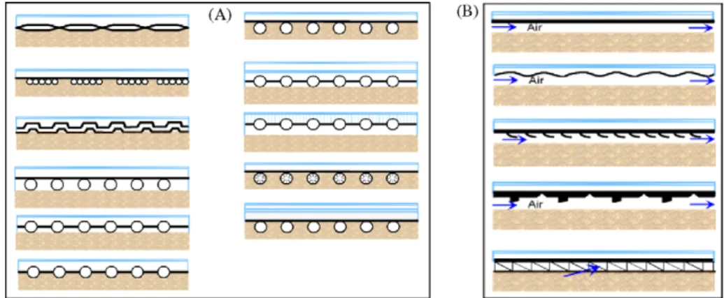
In the same way, we find various forms of absorber in liquid solar collectors (Fig. 13-A).
4.3.2. Energy transmission
Several types of material were used during the 1980s, such as: steel, stainless steel, aluminum and copper. Nowadays, conductive metals are used for the absorber, mainly aluminum and copper. 4.3.3. Energy transfer to the heat-transfer fluid
Increasing the exchange surface and its efficiency, depending on the heat-transfer fluid, was one of the first changes to occur. We
find ‘‘louvered’’ metal sheets [43–48], finned metal sheets
[32,47,49,50,56–58]until the arrival of the porous absorber. These modifications are shown inFig. 13-B.
The design of collectors, and also exchangers, was optimized and the result was to break up the passage of the fluid (air-based collectors) in order to increase the exchange surface, decrease the size of the passage, and thus maximize energy recovery by the fluid
[29,30,32,51,52]. Next, the multiple segmentation of the air passage represented an even greater increase in surface area and led ultimately to a porous absorber[42,45,51,53–55](Fig. 14) for a 10 to 18% increase in thermal efficiency[51]. On the other hand, the problem of considerable losses of charge made it necessary to use forced convection and a fan.
4.4. Evolution of the insulation unit
The insulation unit plays a very important part in solar collector design. Its function is to minimize heat loss at the front and back of the collector.
In the case of flat-plate collectors, heat loss at the back has been reduced by using various insulating materials, from glass wool, through polymeric foams and currently mineral wool[28,35]. To reduce the costs of materials in the system and with a view to sustainable development, new insulation materials have been suggested, based on organic compounds: sheep’s wool, wood fiber and plant fibers in general.
The problem of losses from the front has been minimized by a layer of confined air between the transparent cover and the absorber then by inert gases and lastly by a vacuum.
With regards to the general insulation of the collector, Frei, s/ d, proposes a flat-plate liquid-based collector, which should be available in 2010. This consists of a caisson filled with an inert gas (krypton) to reduce losses via convection. Similarly, the vacuum tubes represent a very significant development in the area of insulation, as heat losses by convection have been
successfully eliminated [35], this has removed the need for
insulation at the front, which means that the heating unit is beginning to evolve in the direction of its environment (law 7).
Unlike flat-plate solar collectors, evacuated collectors have the advantage of being able to track the sun’s trajectory during the daytime thanks to their cylindrical shape, which gives them better efficiency in recovering solar energy and hence a higher level of performance.
Using a vacuum has enabled us to envisage an independent collector recovering energy by latent heat and hence avoid the passage of the heat-transfer fluid in the tube; the tube has become a heat pipe, the tubular absorber traps a small amount of water (or a different fluid, depending on the required temperature) (Fig. 15). This water vaporizes in the absorber tube, the vapor rises in the tube, it condenses in the upper part placed in the water tank to be heated (condenser) and finally it returns to the absorber by gravity in liquid form. The condenser transfers heat to the heat-transfer fluid in the tank[35].
Evacuated tube collectors are still evolving through:
- the arrival of glass absorbers, thus the problems of metal/glass tightness are resolved,
- the incorporation of a heat exchanger in the tube in the case of direct flow collectors,
- the integration of a mirror, parabolic or not, to increase the capture surface,
- the use of phase change fluids.
Fig. 12. Order of evolution of group I.
Fig. 13. Evolution of the transfer unit (liquid-based collector, A and air-based collector, B).
Fig. 14. Increase in the exchange surface area (absorber/fluid). 1452
4.5. Evolution trends
The control/command part of the system (fourth entity) must evolve still further, with improvements in tracking the sun and in the control of transfers. The evacuated tube collector responds to this without a monitoring system, however it is not yet adapted to air-based collectors. We can imagine designing heat pipes with condensers with external fins to heat the air.
Heat losses (law 2) have been reduced thanks to insulation in the front part (layer of confined air or inert gas), at the back of the collector (mineral wool), and by using a vacuum.
The law of coordination of rhythms (law 3) involves adapting the collector to the movement of the sun. The angle of the collector in relation to the sun’s rays ensures that it receives as much energy as possible during the year. Several authors have researched this subject. Shariah et al.[59]suggest a mathematical model which optimizes the angle of the collector. Pucar and Despic[60]have proved that using an adjustable solar collector is much more efficient than a fixed collector, particularly at sunrise and sunset and when the sky is cloudy.
In accordance with law 8 (increase in dynamism of the system), using a system that follows the movement of the sun makes the collector dynamic.
From the point of view of law 4, the collector’s performance has improved as a result of modifications which led to an increase in the surface area of the absorber, making it more efficient; the problem of considerable losses of charge experienced by the heat-transfer fluid still remains to be resolved. The reduction in the size of the collectors by aiming to improve manipulation when it is installed will lead to the construction of smaller and smaller components, the system is thus tending to become more complex. The transition from a 2D collector to a 3D collector (parabolic collector and vacuum collector) means that solar energy collection is optimized. On the other hand, the construction of evacuated tube
collectors has become much more complex because of the integration of new components into the system.
No non-uniform development of entities (law 5) of the system is observed since each of the collector’s components can evolve without affecting the development of the others.
In accordance with law 6, the integration of the collectors into their environment, the drying kiln and the storage system is ongoing. The air-based collector is integrated into the drying kiln
[10]and the evacuated system is integrated into the storage (heat pipes); nevertheless, this last solution has not yet found its place in storage for industrial use.
The application of selective coatings on the absorber imposes a development on this component at micro-level (law 7). Analysis of selective coatings represents years of research in order to find one or several materials that have the qualities of high absorptance and low reflectance to solar radiation.
5. Proposed evolution
In order to situate the degree of evolution that has taken place in existing solar kiln systems, see Fig. 16which represents the points of view in accordance with the eight laws of evolution. For each law, the score applied to the degree of evolution throughout its existence is based on concepts which have not evolved (0) to
very evolved systems (3). The suggestion in Fig. 7 takes up
interesting known concepts and adds foreseeable evolutions taken from the radar plot, i.e.:
- arrangement 2,
- use of storage with independent heating,
- integration of an air heater in the storage and not in the drying chamber,
- management of different drying cycles according to quality control of the product.
Fig. 15. Insulation in a vacuum (tube with direct flow, A; heat pipe, B).
Optimization of the parameters relevant to the drying process, design of the units, the series of cycles and reducing ownership and land costs have yet to be carried out.
Concerning the heating units, we have seen that liquid-based collectors are now extremely efficient (glass tube ensuring static tracking of the sun), designed in such as way as to ensure that maintenance is straightforward (collectors with heat pipes). Air-based collectors, however, have not evolved in the same way and one suggestion is to use heat pipe collectors by placing finned surfaces on the condenser and air side. In this case the air no longer sees the sun and passes into a pipe with internal fins into which the heat pipes are incorporated. In this way we have the same flexibility for maintenance. This flexibility should be used for cleaning the absorber surfaces.
6. Conclusion
We have proposed a method for analyzing currently available solar kilns and associated patents. This method is based on an organic and functional approach to analyze the arrangements and the different units of a kiln.
The laws of evolution for technological systems were used to describe the solutions found and to situate them in terms of development. Thus, it was possible to suggest integrating a storage system and a new adapted arrangement. Similarly, a new air-based collector is a possibility, based on the combined analysis of development trends of air-based collectors and vacuum collectors.
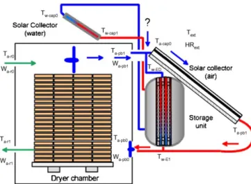
Fig. 17shows the kiln that we are currently designing (based on the proposal shown inFig. 16) in the context of a doctoral thesis study in our Laboratory, supported by CONACyT (Mexico). The heating unit consists of insulated air-based collectors and confined air. The liquid-based collectors linked to the storage unit are more rugged for reasons of sturdiness and cost, but they could easily be replaced with evacuated tube collectors.
References
[1] Plumptre RA, Jayanetti DL. Solar heated timber drying kilns: a manual on their design and operation. Bucks: TRADA Technology Ltd.; 1996.
[2] Savransky SD. Engineering of creativity. Introduction to TRIZ methodology of inventive problem solving. Boca Raton, Florida: CRC Press; 2000.
[3] Scaravetti D, Nadeau JP, Pailhes J, Se´bastian P. Structuring of embodiment design problem based on the product lifecycle. Int J Prod Dev 2005;2(1–2):47–70. [4] Scaravetti D, Pailhes J, Nadeau JP, Se´bastian P. Aided decision-making for an
embodiment design problem. In: Bramley A, Brissaud D, Coutellier D, McMa-hon C, editors. Advances in integrated design and manufacturing in mechan-ical engineering. Dordrecht: Springer; 2005. p. 159–72.
[5] Nadeau JP, Pailhes J. Inte´gration de l’innovation et des sensations utilisateur en conception pre´liminaire par le biais de l’analyse fonctionnelle. In: Roucoules L, Yannou B, Benoıˆt E, editors. Inge´nierie de la conception et cycle de vie du produit. Paris: Herme`s; 2006. p. 43–62.
[6] Simpson WT. Drying technology issues in tropical countries. In: International Union of Forestry Research Organizations. Conference (IUFRO); August 23–28, 1992.p. 497–507.
[7] Simpson WT, Tschernitz JL. Solar Dry Kiln for tropical latitudes. Forest Prod J 1984;34(5):25–34.
[8] Wengert ME, Meyer DA. Processing trees to lumber for the hobbyist and small business. USA: University of Wisconsin-Madison; 1992 August.
[9] Maldonado ED, Peck EC. Drying by solar radiation in Puerto Rico. Forest Prod J 1962;12(10):487–8.
[10] Haque MN. Modelling of Solar Kilns and the Development of an Optimised Schedule for Drying Hardwood Timber. PhD Thesis, University of Sydney. Sydney, Australia; 2002.
[11] Welwa HN, Khater HA, Enayet MM, Hashish MI. Experimental evaluation of solar kiln for drying wood. Drying Technol 2004;22(4):703–17.
[12] Luna D. Construccio´n y validacion de un Secador Solar para madera aserrada. Te´sis Maestrı´a. Chapingo, Me´xico: Universidad Autonoma Chapingo; 2002. [13] Viehbeck P, Viehbeck G. Solar Drying of sawn timber in Kingston, Jamaica.
German Appropriate Technology Exchange; 1997.www.2.gtz.de/Basin/gate/ cs10/timber1.pdf.
[14] Martı´nez-Pinillos CE. Disen˜o y ensayo de un secador solar para Madera. Madera y Bosques 1997;3(2):13–28.
[15] Lumley GT, Choong ET. Technical and economic characteristics of two solar kiln designs. Forest Prod J 1979;29(7):49–56.
[16] Santini EJ. Secagem de Madeira serrada em estufa solar e sua comparacao com os metodos convencionais. Rev Floresta 1981;5–13.
[17] Gough DK. Timber seasoning in a solar kiln. Sunworld 1980;4(6):204–7. [18] Kumar S. Utilisation of solar energy in India. Forest Prod J 1981;31(9):10–2. [19] Reuss M, Benkert ST, Aeberhard A, Martina P, Raush G, Rentzell BV, et al. Modelling and experimental investigation of a pilot plant for solar wood drying. Sol Energy 1997;59(4–6):259–70.
[20] Fuwape IA, Fuwape JA. Construction and evaluation of a timber drying solar kiln. Bioresour Technol 1995;52(1995):283–5.
[21] Plumtre RA.In: Some thoughts on design and control of solar timber kilns. IUFRO Division V Conference; 1983.
[22] Bois PJ. Constructing and Operating a Small Solar-Heated Lumber Dryer. Forest Products Utilization: Technical Report No. 7. USDA Forest Service, Madison, Wisconsin; 1977.
[23] McCormic PO. Solar heating system for kiln drying lumber. Sunworld 1980;4(6):204–7.
[24] Read WR, Choda A, Copper PI. A solar timber kiln. Sol Energy 1974;(15):309–16. [25] Anon. Solar kiln can dry 3000 bd ft of lumber. Timber/West, March, 1982:26–
27.
[26] Robbins AM. Solar lumber kilns: design ideas. New Mexico Energy Research and Development Institute, University of New Mexico; 1983.
[27] Duffie JA, Bechman WA. Solar engineering of thermal processes, 3rd ed., New Jersey: John Wiley and Sons Inc.; 2006.
[28] Bernard J. Ge´nie Energe´tique. Energie Solaire: Calculs et optimisation. Ed. Ellipses; 2004.
[29] Hegazy AA. Optimum channel geometry for solar air heaters of conventional design and constant flow operation. Energy Convers Manage 1999;40:757–74. [30] Hegazy AA. Comparative study of the performances of four photovoltaic/
thermal solar air collectors. Energy Convers Manage 2000;41:861–81. [31] Ong KS. Thermal performance of solar air heaters experimental correlation. Sol
Energy 1995;55(3):209–20.
[32] Ekechukwua OV, Norton B. Review of solar-energy drying systems III: low temperature air-heating solar collectors for crop drying applications. Energy Convers Manage 1999;40:657–67.
[33] Choudhury C, Chauhan PM, Garg HP. Design curves for conventional solar air heaters. Renewable Energy 1995;6(7):73–749.
[34] Njomo D. Unglazed selective absorber solar air collector: heat exchange analysis. Heat Mass Transfer 2000;36:313–7.
[35] Peuser FA, Remmers KH, Schnauss M. Installations solaires thermiques: con-ception et mise en œuvre. Le Moniteur; 2005.
[36] Frei U. Solar thermal Collectors, state of the art and further development. SPF. s/d. [37] Naphon P, Kongtregool B. Theoretical study on heat transfer characteristics and performance of the flat-plate solar air heaters. Heat Mass Transfer 2003;30(8):1125–36.
[38] Tsilingiris PT. Heat transfer analysis of low thermal conductivity solar energy absorbers. Appl Eng 2000;20:1292–314.
[39] Karim MA, Hawlader MNA. Development of solar air collectors for drying applications. Energy Convers Manage 2004;45:329–44.
[40] Njomo D, Daguenet M. Sensitivity analysis of thermal performance of flat plate solar air heaters. Heat Mass Transfer 2006;42:1065–81.
[41] Gao W, Lin W, Liu T, Xia C. Analytical and experimental studies on thermal performance of cross-corrugated and flat-plate solar air heaters. Appl Energy 2007;84:425–41.
[42] Mittal MK, Varshney L. Optimal thermohydraulic performance of a wire mesh packed solar air heater. Sol Energy 2006;80:1112–20.
[43] Ahmed-Zaı¨d A, Moulla A, Hantala1 MS, Desmons JY. Ame´lioration des per-formances des capteurs solaires plans a` air: application au se´chage de l’oignon jaune et du hareng. Rev Energie Renouvelable 2001;4:69–78.
Fig. 17. Solar dryer with energy storage.
D. Luna et al. / Renewable and Sustainable Energy Reviews 13 (2009) 1446–1455 1454
[44] Ammari HD. A mathematical model of thermal performance of a solar air heater with slats. Renewable Energy 2003;28:1597–615.
[45] Naphon P. Effect of porous media on the performance of the double-pass flat plate solar air heater. Int Commun Heat Mass Transfer 2005;32:140–50. [46] Ho-Ming Y, Chii-Dong H, Chi-Yen L. Effect of collector aspect ratio on the
collector efficiency of upward type baffled solar air heaters. Energy Convers Manage 2000;41:971–81.
[47] Pottler K, Dippel CM, Beck A, Fricke J. Optimized finned absorber geometries for solar air heating collectors. Sol Energy 2000;67(1–3):35–52.
[48] Al-Nimr MA, Damseh RA. Dynamic behaviour of baffled solar air heaters. Renewable Energy 1998;13(2):153–63.
[49] Apurba L, Sainib JS, Solankib SC. Second law optimization of a solar air heater having chamfered rib–groove roughness on absorber plate. Renewable Energy 2007;32:1967–80.
[50] Karwa R, Solanki SC, Saini JS. Thermo-hydraulic performance of solar air heaters having integral chamfered rib roughness on absorber plates. Energy 2001;26(2):161–76.
[51] Mohamad AA. High efficiency solar heater. Sol Energy 1997;60(2):71–6. [52] Ramadan MRI, El-Sebaii AA, Aboul-Enein S, El-Bialy E. Thermal performance of
a packed bed double-pass solar air heater. Energy 2007;32:1524–35. [53] Fournier M, Maurissen Y. Simulation du fonctionnement de capteurs solaires a`
air de type toˆle et de type absorbeur poreux. J Phys 1993;3:2249–60. [54] Varshney L, Saini JS. Heat transfer and friction factor correlations for
rectan-gular solar air heater duct packed with wire mesh screen matrices. Sol Energy 1998;62(4):255–62.
[55] Ahmad A, Saini JS, Varma HK. Effect of geometrical and thermophysical characteristics of bed materials on the enhancement of thermal performance of packed bed solar air heaters. Energy Convers Manage 1995;36(12):1185– 95.
[56] Mittal MK, Varun, Saini RP, Singal SK. Effective efficiency of solar air heaters having different types of roughness elements on the absorber plate. Energy 2007;32:739–45.
[57] Aharwal KR, Gandhi BK, Saini JS. Experimental investigation on heat-transfer enhancement due to a gap in an inclined continuous rib arrangement in a rectangular duct of solar air heater. Renewable Energy 2008;33(4):585–96. [58] Esen H. Experimental energy and energy analysis of a double-flow solar air
heater having different obstacles on absorber plates. Building Environ 2008;43(6):1046–54.
[59] Shariah A, Al-Akhras MA, Al-Omari IA. Optimizing the tilt angle of solar collectors. Renewable Energy 2002;26:587–98.
[60] Pucar M, Despic A. The effect of diffuse/indirect light on the energy gain of solar thermal collectors. Renewable Energy 2005;1–10.
[61]http://www.jonathan-guest.co.uk/.
[62] Coulibaly FBM, Amouroux M. Optimisation de la commande d’un se´choir solaire a` bois. J Phys 1992;2:701–14.
[63] Solano R. Construccio´nde una secadora solar para maderas. Primer Simposio: energı´a solar, fundamentos y aplicaciones. Costa Rica: Editorial Tecnolo´gica de San Jose´; 1979. p. 313.
[64] Rosen HN, Chen PYS. Drying lumber in a kiln with external solar collectors. New process alternatives in the forest products industries. Am Inst Chem Eng Symp Ser 1980;76(200):82–9.
[65] Chen PYS, Helmer WA, Roen HN, Barton DJ. Experimental solar-dehumidifier kiln for lumber drying. Forest Prod J 1982;32(9):35–41.
[66] Yand KC. Solar kiln performance at a high latitude, 48 N. Forest Prod J 1980;30(3):37–40.
[67] Steinmann DE, Vermaas HF, Forrer JB. Solar timber drying kilns: Part I: Review of previous system and control measures and description of an automated solar kiln. J Inst Wood Sci 1980;48:254–7.
[68] Steinmann DE, Vermaas HF, Forrer JB. Solar timber drying kilns: Part II: Microprocessor control of a solar kiln. J Inst Wood Sci 1980;49:27–31. [69] De Vore JB, Denny GS, Harper TS. A commercially viable solar wood drying kiln
system. Drying Technol 1999;17(1–2):271–83.
[70] Haque MN, Langrish TAG. Stack-wide in the modelling of solar kilns for drying timber. Drying Technol 2001;19(1):99–114.