Science Arts & Métiers (SAM)
is an open access repository that collects the work of Arts et Métiers Institute of
Technology researchers and makes it freely available over the web where possible.
This is an author-deposited version published in:
https://sam.ensam.eu
Handle ID: .
http://hdl.handle.net/10985/7626
To cite this version :
Corinne NOUVEAU, Chafik LABIDI, Robert COLLET, Yacine BENLATRECHE, Mohamed Abdou
DJOUADI - Effect of surface finishing such as sand-blasting and CrAlN hard coatings on the
cutting edge’s peeling tools’ wear resistance - Wear - Vol. 267, n°5-8, p.1062-1067 - 2009
Any correspondence concerning this service should be sent to the repository
Administrator :
archiveouverte@ensam.eu
Short communication
Effect of surface finishing such as sand-blasting and CrAlN hard coatings on the
cutting edge’s peeling tools’ wear resistance
C. Nouveau
a,∗, C. Labidi
a, R. Collet
a, Y. Benlatreche
a, M.-A. Djouadi
baLaBoMaP, Arts et Métiers ParisTech, Rue Porte de Paris, F-71250, Cluny, France
bInstitut des Matériaux Jean Rouxel (IMN) UMR 6502, 2 rue de la Houssinière, B.P. 32229, F-4322 Nantes cedex 3, France
Keywords: Sand-blasting CrAlN Wood machining Wear resistance
a b s t r a c t
The aim of this study is first to define the effect of a surface finishing such as sand-blasting on the geometry of a wood cutting tool and its wear resistance. In addition, the effectiveness of surface coatings like CrAlN deposited by physical vapor deposition (PVD) technique on conventional and sand-blasted cutting edges was studied. A reference tool and different sand-blasted ones were tested by micro-peeling of beech in a laboratory. Microscopic observations, cutting forces measurement and cutting wear tests were carried out to quantify the behaviour of these tools. The results obtained showed that the artificial wear by sand-blasting leads to an increase in the wear resistance and coating effectiveness, and completely changes the type of damage done to the tools. The sand-blasting application combined or not with CrAlN coating showed an improvement in the wear resistance of the tools and a modification of the forces during the peeling process. The effectiveness of the CrAlN layers was improved thanks to the sand-blasting treatment and then the duplex ones performed better.
1. Introduction
One of the major problems concerning wood industry tools is the occurrence of nicks on the cutting edge mainly due to the impact of knots, or foreign bodies that green wood frequently contains. This phenomenon is accentuated by the small tool angle of the wood machining tools. In the peeling process, two situations may occur: first, when the dimensions of the nicks are no more than 200m in depth, the operator must intervene with pumice in order to sharpen the damaged area. In this case, production is not affected. Second, if the edge is totally broken (size of nicks exceeds 1 mm of depth), a change of tools is necessary. These repeated stops induce economic losses and harder working conditions for the operators. Previous studies showed the effectiveness of surface coatings such as hard layers obtained by PVD methods (TiN, CrN, etc.) or surface treat-ments such as nitriding and duplex treattreat-ments against wear in wood machining and especially in peeling[1–4].
The low cutting angle (19–22◦) is the main problem and is responsible for significant abrasive wear of the tool during its run-ning time. Nevertheless, the limitation to commercialization of modified tools in the wood industry is the low effectiveness of the protective coatings on the cutting edge. In previous studies, Sheikh-Ahmad et al.[5]showed that the modification of the
cut-∗ Corresponding author. Tel.: +33 3 85595335; fax: +33 3 85595370. E-mail address:nouveau@cluny.ensam.fr(C. Nouveau).
ting angle of carbide tools with a stone increased the adhesion of diamond-like-carbon (DLC) layers and then decreased tool wear. Morita et al.[6]wanted to observe the influence of surface treat-ments such as chemical (Murakami/H2O2–H2SO4) and mechanical (sand-blasting/HCl–HNO3) solutions on DLC (5–20m thick) layer behaviour during routing of Medium Density Fibreboard (MDF) and bulk wood. The Murakami-based treatment was not effective but the sand-blasted one led to an improvement in the wear resistance of the tool whatever the type of wood machined. This was explained by the high surface roughness and edge radius obtained after this treatment which allowed better adhesion of the DLC layers. Based on these earlier works, we combined the preparation of the cutting edge by sand-blasting and a surface treatment such as a PVD CrAlN hard coating and compared their wear resistance with unmodified tools.
2. Materials and methods 2.1. Cutting tools
The cutting tools were made of 90CrMoV8 (“La Forézienne-MFLS”, France trademark) steel (Table 1) currently used in the peeling process. The geometry of the tools is represented inFig. 1. The cutting edge was polished to obtain a Ra= 0.2–0.5m and a
Rt= 1m with SiC disks (no. 180).
Before deposition, the cutting tools were ultrasonically cleaned with alcohol and in situ etching under an argon ion bombardment for 5 min.
Table 1
Composition, thermal treatment and hardness of 90CrMoV8 steel tools.
90 CrMoV8 Composition (%) Fe 88 C 0.5 Si 1 Mn 0.5 P – S – Cr 8 Mo 1.5 W – V 0.5
Thermal treatment Hardening 1020–1050◦C—1 h Quenching 520–580◦C Hardness (HRC) 54–56
2.2. Sand-blasting process
Wet sand-blasting is employed in operations such as aspect improvement, cleaning, etching, substrates preparation before deposition, removal of wire edge, stress preview or decontam-ination [7,8]. The treated surfaces present an almost perfect physico-chemical property state. This process is especially adapted to brittle mechanical parts as our micro-peeling knives. It presents many advantages such as no dust, the possibility to employ fine and very fine abrasives such as quartz or silica which are not employed in dried sand-blasting and finally, it reduced fragmentation thanks to the water film; the inclusion risks are limited because water plays the role of a shock absorber.
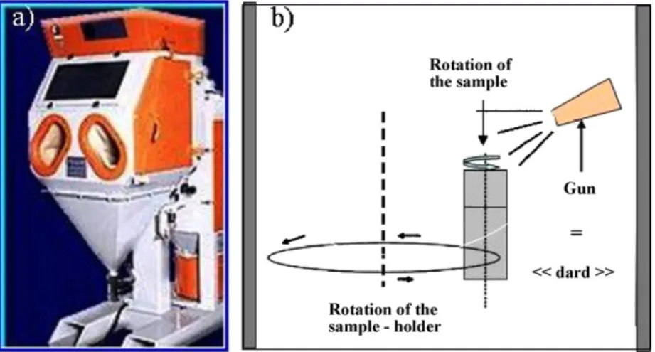
The sand-blasting operations were conducted on a commercial sand-blasting machine VAPOR BLAST-ELVE HEC 221 from IonBond (Fig. 2A). We sand-blasted the tools automatically according to the method represented inFig. 2B. The tool is in rotation and simul-taneously sputtered with a mixture composed of sand grains and water under high pressure thanks to a gun called ‘dard’. The mixture employed was composed of corundum grains (15m of diameter) and water under 4.5 bar. In our case, the gun was placed perpen-dicularly (parallel to the rake face: seeFig. 4) and at a distance of 100 mm from the cutting edge. The process was composed of cycles which consist in going from point A to point B and coming back to point A (=1 cycle, 20 s) (Fig. 2B).
For this study, two micro-peeling knives were sand-blasted for 1 cycle (20 s of treatment) and two others were treated the same way but for two cycles (40 s of treatment) to check the influence of the
Fig. 1. Geometry of a micro-peeling tool (in mm) and 1 sand-blasting cycle
(A→ B → A).
sand-blasting duration on the cutting performance of the treated cutting tools.
2.3. CrAlN coatings
The CrAlN coatings were synthesized by a dual RF magnetron sputtering with a pure CrAl target (75 at.% of Cr and 25 at.% of Al) at a working pressure of 4bar, a target bias voltage of −900 V, a Ar + N2gas mixture (75%/25%) for 90 min (∼2 m thick). The layers were deposited on both faces of the tools. Thus, one of the tools sand-blasted during 20 s (1 cycle) and one during 40 s (2 cycles) were CrAlN coated.Table 2summarizes the tested knives in micro-peeling.
Fig. 3. Micro-peeling system (A) and peeling process with the forces applied during the tests (B).
Table 2
Micro-knives tested in micro-peeling.
Knives Number of cycle/sand-blasting duration CrAlN film
Untreated 0 No Sand-blasted-1 1/20 s No Sand-blasted-2 2/40 s No Duplex-1 1/20 s Yes Duplex-2 2/40 s Yes 2.4. Micro-peeling process
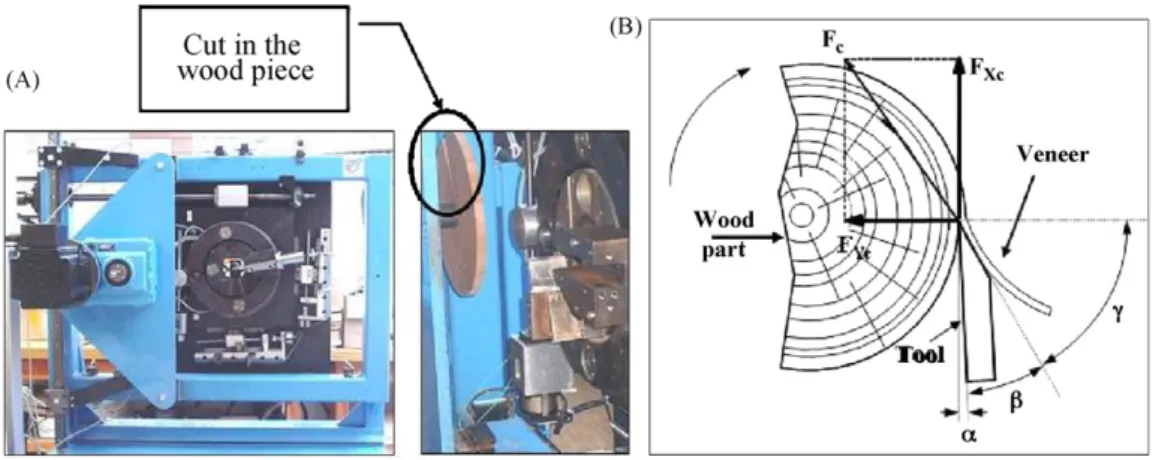
The micro-peeling was conducted on an instrumented machine. The tests were made with bulk beech wood cut into disks as shown inFig. 3A. The micro-peeling process and the applied forces that occur during the machining are represented inFig. 3B (especially
FXcand FYcforces).
The disks were kept in water at an ambient temperature until the machining tests. Beech was chosen because it is the most employed bulk wood specie in industrial peeling. It is worthy to note that beech wood pieces were cut to simulate shocks during the machin-ing process. The cuttmachin-ing conditions are summarized inTable 3.
2.5. Characterization and wear measurement
An optical microscope (OM-Olympus Vanox-T AH-2) was used to measure the reduction of the cutting edge and a scanning electron microscope (SEM-JEOL JSM-5900LV) to observe the morphology of the cutting edge after sand-blasting, after deposition, after machin-ing, and also the retreat of the layer due to wear. Energy dispersive spectroscopy (EDS) microanalyses were also performed to check the composition of the CrAlN coatings. The forces (FXc and FYc) were determined during the micro-peeling process with a multi-analyser system (PULSE of Bruël & Kjaer). It allows registering the temporal signals and numerical processing at the same time. The sampling frequency was set up to 65,536 Hz which allows saving reliable signals at frequencies up to 25.6 kHz, considering the Shan-non criteria and the real filter capabilities. The scatter of the forces measurement was±5 N. Table 3 Cutting conditions. Veneer thickness (mm) 1 Linear speed (m/s) 1 Cutting path (m) 3000 Clearance angle (◦) 1
Fig. 4. Measurement of the reduction of the micro-peeling knives cutting edge.
In peeling, the reduction of the cutting edge is representative of the tool wear. This method of wear quantification is commonly employed in wood machining[9–11]. The optical method that we used is represented inFig. 4. An average value is calculated from 50 measurement points taken each 350m, the baseline is the part of the knife which is never in contact with the wood piece during the peeling process. The optical observation of the cutting edge was done and a numerical sensor allows the observation of the cutting edge on a computer. The measurement of the wear is made thanks to the “ANALYSIS” software (±0.5 mm for a magnification of 590 which equals to an error of 1m).
3. Results and discussion 3.1. SEM and EDS
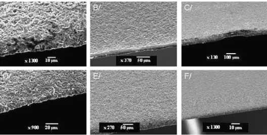
The SEM images from sand-blasted and duplex-treated cutting edges are presented inFig. 5. It is obvious that the CrAlN coating protects the cutting edge well according to these SEM observations (Fig. 5A and D). It presents an inhomogeneous surface state with a certain roughness. Concerning the radius of the cutting edge, we can check inFig. 5B (around 5m) and E that it is bigger in the case of two cycles (40 s) of sand-blasting which is logical. Finally, some imperfections on the cutting edge before machining (Fig. 5C) can be seen which is probably caused by the grinding during the knife preparation. Nevertheless, inFig. 5F a perfect cutting edge radius state is observed.
The composition of the CrAlN coatings was verified by EDS (Table 4). They present the same content of Al and Cr and a maxi-mum of nitrogen. Nevertheless, they also contain 6 at.% of oxygen but we can consider that it is negligible and will not interfere in the mechanical properties of the coatings.
Fig. 5. SEM observations of the cutting edge after sand-blasting for 1 (A–C) or 2 cycles (D–F) and CrAlN deposition.
Table 4
EDS quantification results of a CrAlN coating. Element At.% O 6 N 35 Al 30 Cr 29 3.2. Micro-peeling of beech
The wear of the cutting edges versus the cutting path is repre-sented inFig. 6. After 2000 m of cutting, the sand-blasted knives are more wear resistant than the unmodified ones but at the end of the test (3000 m) they behave in the same way. Besides, the duplex-treated ones (1 or 2 cycles) are effective until 3000 m. The duplex-treated knife with two cycles is the most wear resistant. Indeed, it permits to machine almost four times more than an unmodified tool while the duplex-treated knife with 1 cycle permits to machine only two times more but this result is more promising than the sand-blasting only treatment.
The worst cutting knives presented a wear of 100m which is high and probably caused the beginning of scratches on the veneer produced and, as said in Section1, the objective of the lathe indus-tries is to decrease the loss of productivity caused by the machine stopping. So, if we consider that a wear of 100m requires the machine being stopped to sharpen the knife, for a wear of only 50m, we first machined more (better wear resistance, seeFig. 6) and second one can suppose that we are far from this limit that
Fig. 6. Wear of the edges versus the cutting path in micro-peeling of beech.
imposes to stop the machine to sharpen the knife. To summarize, a wear of 50m instead of 100 m, or worse 200 m as mentioned in Section1, permits us to conclude that the knife is more wear resistant and probably does not present nicks yet but there is still a good quality of the produced veneer.
3.3. Surface state of the cutting edges
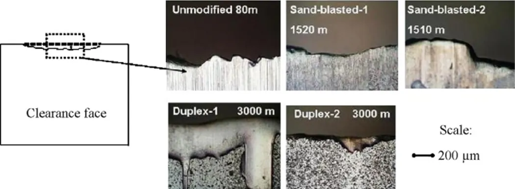
The surface state of the cutting edges was observed by OM dur-ing the micro-peeldur-ing process (Fig. 7). The unmodified knife shows a brittle damage only after 80 m of cutting, which could explain its bad wear resistance. This result confirms the above-mentioned ones because a brittle damage obtained only after 80 m of cutting will be responsible for a bad veneer quality (scratches) after 3000 m of cutting. On the contrary, both of the sand-blasted knives present a ductile damage after 1500 m of cutting. As a matter of fact, one can suppose that: the sand-blasting treatment modified the cutting edge radius and consequently its geometry. Besides, this process which consists in a bombardment of the cutting edge under high pressure could be responsible for a stress release of the steel and finally for the change of damage type from brittle to ductile. That is the reason why they performed better than the unmodified knife. At the end of the test (3000 m) they still have the same ductile dam-age but with a significant cutting edge radius which means that above 2000 m of cutting, the steel material cannot cut any longer and that the forces during the cutting process should be responsi-ble for the increase of its abrasive wear (especially in the case of the rake face which is the most stressed because it is in direct con-tact with the veneer). To conclude, even if the sand-blasted knives have a ductile damage which allows no veneer quality change, they are not wear resistant enough above 2000 m of cutting. It is not the case of both duplex-treated knives which showed the best perfor-mance. Indeed, after 3000 m of cutting, the duplex-1 treated knife presented a ductile damage and a small retreat of the coating while the duplex-2 treated one, which performed the best, still has a cut-ting edge with a very good surface aspect and is still protected by the coating. The difference in behaviour between these two knives could be explained by the duration of the sand-blasting treatment: only 1 cycle does not seem to be enough with or without coat-ing: to summarize, the sand-blasted-2 and the duplex-2 treated knives performed better than the others. With only 1 cycle of sand-blasting, one can suppose that the radius of the cutting edge is still too small and similar to the unmodified one. A combination of sand-blasting with a CrAlN coating protects the edge radius and leads to better performance. In order to understand the behaviour of the coated tools, we used SEM observations. On the clearance face of
Fig. 7. Surface state of the cutting edges during micro-peeling of beech.
Fig. 8. Cutting edge of the duplex-2 cutting tool after 3000 m of peeling.
the tool, CrAlN coating showed a little retreat from the edge (15m, not visible in OM seeFig. 7) and this along its total length (Fig. 8). This same small coating retreat was also noted on the rake face.
It is known that in the case of peeling tools, the low cutting edge angle of 20◦ is responsible for its high wear during the run-ning in time of the tool (i.e. during the first meters of cutting). But a surface finishing such as sand-blasting changed the geom-etry of the cutting edge and increased its radius before machining resulting in lower damage during the first meters of cutting because wear has already occurred. As a consequence, the wear resistance is improved because of the decrease of the cutting forces (see Section
3.4). The adhesion of the coating is better on a sand-blasted tool for 2 cycles because the duration of the treatment is probably enough to create numerous nucleation sites for the following layer near the cutting edge. However, in peeling, the face in contact with the veneer produced during the process should be protected enough. As the CrAlN coatings tested only retreated by a few microns on
this face, they protect it enough against the veneer friction and improve the tool wear resistance. In conclusion, the combination of sand-blasting with a CrAlN hard layer probably permits to keep the veneer quality unchanged and to protect the steel cutting tool from wear until the end of the test (the good adhesion of the layer due to the creation of nucleation sites during sand-blasting resulted in lower friction of the veneer against the two faces of the tool, thus leading to a better wear resistance).
3.4. Forces measurement
In order to understand the wear behaviour of the cutting tools in micro-peeling, the average forces FXc and FYc (Fig. 3B) were measured (Fig. 9). The FXcforce represents the effort of the wood piece applied on the cutting tool, therefore the energy consump-tion during the micro-peeling process. It is noteworthy that at 2000–2500 m of cutting all the knives present the same FXcvalue (except the sand-blasted-1 knife at 2500 m); consequently we must comment the different knives’ behaviour before and after these 2000–2500 m of cutting. But it also seems that the relation between the energy consumption (i.e. the FXcvalues) and the tool behaviour as shown inFig. 6is not significant for all knives. First, it is obvious that the unmodified tool shows the highest FXcvalues, as expected, from the beginning to 1500 m of cutting, which is probably respon-sible for its bad wear resistance as shown inFig. 6. Besides, the sand-blasted-1 tool also has high FXcvalues from 250 to 500 m of cutting which is confirmed by a similar behaviour to the unmodi-fied tool inFig. 6. Nevertheless, from 1000 to 2000 m of cutting, this tool presents lower FXcvalues and as a consequence performed bet-ter than the untreated one as seen inFig. 6. From 250 to 500 m of cutting, the sand-blasted-2 knife shows low FXcvalues (as a conse-quence a good wear resistance, seeFig. 6) but these values increase with the cutting path until 1500 m where it performed as the sand-blasted-1 tool. As mentioned before, no relation between the energy
consumption and the wear behaviour was obvious in the case of the duplex-1 tool. As a matter of fact, this tool has a good wear resis-tance from 250 to 1000 m of cutting while its FXcvalues are very high. Moreover, as expected, the duplex-2 knife behaved the best (Fig. 9A) with the FXclowest values during the entire cutting test. That could explain its improved performance in comparison to the other knives (Fig. 6). If we consider what happened at the end of the cutting process (at 3000 m), the sand-blasted-1 and unmodified tools present similar FXcvalues but higher than the ones observed for the three other knives (which also have similar FXcvalues). To conclude, it seems that the energy consumption can be a significant parameter but not sufficient to determine the wear behaviour of a cutting tool. Nevertheless, the influence of the number of cycles of sand-blasting and the CrAlN layers presence were obvious; the knife sand-blasted with 2 cycles (significant change of the cutting edge geometry) and the coated ones (decrease of the friction between the wood piece and the steel tool) showed the lowest energy con-sumption at the end of the test. To try to better understand how the knives behaved we also studied the FYcvalues as shown inFig. 9B. The FYcforce represents the step when the knife refuses to cut (the force becomes negative). It is obvious inFig. 9B that the unmod-ified and sand-blasted-1 knives present the worst behaviour at the end of the cutting test because their FYc values are close to zero (at 2500 and 3000 m for the sand-blasted-1 and the unmodified knife, respectively) so most likely negative had we continued the test (rejection of cutting). This result confirms the ones obtained in
Fig. 6where these two knives showed the worst wear behaviour at the end of the cutting test. The three other knives never refuse to cut even after 3000 m but it is worthy to note that from 0 to 1000 m, the sand-blasted treated knives have a higher FYcvalue than the duplex-treated ones and above, it is the contrary.
Concerning the sand-blasted-2 treated knife, it presents lower values than the duplex-treated ones from 1500 m of cutting which can explain its lower wear resistance (Fig. 6) in comparison to the duplex-treated knives even if its FXcforce, so its energy consump-tion, is almost the same. In conclusion, it seems that the FYcforce is a better criterion compared with FXcone to get an idea about the wear behaviour of a cutting tool.
4. Conclusions
The influence of sand-blasting and duplex treatments (sand-blasting + CrAlN deposition) on the wear resistance of micro-peeling tools was studied. The knives which were only sand-blasted performed better than the unmodified one and that sand-blasted for 2 cycles is better than only for 1 cycle. The duplex-treated knives performed better than the sand-blasted only ones. The best performances were shown by the duplex-2 (sand-blasting for 2 cycles + CrAlN deposition) knife which allows four times more
machining than the unmodified knife. Furthermore, the coating made on the sand-blasted knife for 1 cycle (with the smallest edge radius) leads to poor adhesion on the cutting edge. However, the adhesion was improved when sand-blasted for 2 cycles (retreat of a few microns). It was also obvious that the FXcforce was not the main criterion in comparison to the FYcforce which gave more informa-tion about the behaviour of the tool during the machining process. The influence of the sand-blasting number of cycles and the CrAlN layers presence were effective to obtain tools which present a good wear resistance, low energy consumption and no rejection to cut after 3000 m of peeling process. Finally, according to this study we would advise tool suppliers to treat their knives to modify the cut-ting edge geometry (by sand-blascut-ting or another treatment) and to the end users, it is obvious that a tool treated before its first use would be more effective than one in the market today.
Acknowledgements
The authors would like to thank IonBond (Chassieu-France) who made the sand-blasting treatments and the Regional Council of Bur-gundy and CTBA (Wood and Furniture Technical Centre) for their financial support.
References
[1] C. Nouveau, J. Jorand, C. Decès-Petit, C. Labidi, M.A. Djouadi, Influence of car-bide substrates on tribological properties of chromium and chromium nitride coatings: application to wood machining, Wear 258 (1–4) (2005) 157–216. [2] C. Labidi, R. Collet, C. Nouveau, P. Beer, S. Nicosia, M.A. Djouadi, Surface
treat-ments of tools used in industrial wood machining, Surf. Coat. Technol. 200 (1–4) (2005) 118–122.
[3] A. Chala, L. Chekour, C. Nouveau, C. Saied, M.S. Aïda, M.-A. Djouadi, Study of the duplex treatment on 32CrMoV13 low alloy steel: application in wood machin-ing, Surf. Coat. Technol. 200 (1–4) (2005) 512–516.
[4] P. Beer, J. Rudnicki, C. Nouveau, M.-A. Djouadi, S. Bugliosi, R. Collet, Study of some parameters of selected steels in reference to the wood cutting performance of knives, in: Proceedings of the 11th Int. Wood Machining Seminar IWMS, Matsue, Japan, 2003, pp. 480–486.
[5] J.Y. Sheikh-Ahmad, J.S. Stewart, H. Feld, Failure characteristics of diamond-coated carbides in machining wood-based composite, Wear 255 (7–12) (2003) 1433–1437.
[6] T. Morita, J.Y. Sheikh-Ahmad, K. Banshoya, T. Tsutsumoto, Y. Murase, On the cut-ting performance of diamond-coated cemented carbide tools pretreated with Murakami/H2O2–H2SO4solution, Forest Products Journal 50 (1) (2000) 67–73.
[7] F. Klocke, T. Krieg, Coated tools for metal cutting—features and applications, Annals of the CIRP 48 (2) (1999) 1–11.
[8] H.K. Tonshoff, A. Mohlfeld, C. Spengler, C. Podolsky, PVD coated tools for metal cutting application, in: ‘THE Coatings’ Proceedings (14th–15th October 1999), Thessaloniki (Greece), 1999, pp. 1–20.
[9] S. Aratake, Effects of edge wear on machinability in wood cutting by a small diameter bit with numerically controlled router, Mokuzai Gakkaishi 39 (4) (1993) 389–395.
[10] T. Morita, K. Banshoya, T. Tsutsumoto, Y. Murase, Effects of work materials on cutting performance of diamond-coated cemented carbide tools, Forest Prod-ucts Journal 48 (5) (1998) 43–50.
[11] S. Warren, Method for measuring wear in veneer chipper and waferizing knives, Forest Products Journal 39 (5) (1989) 37–38.