HAL Id: hal-02405165
https://hal.archives-ouvertes.fr/hal-02405165
Submitted on 11 Dec 2019HAL is a multi-disciplinary open access archive for the deposit and dissemination of sci-entific research documents, whether they are pub-lished or not. The documents may come from teaching and research institutions in France or abroad, or from public or private research centers.
L’archive ouverte pluridisciplinaire HAL, est destinée au dépôt et à la diffusion de documents scientifiques de niveau recherche, publiés ou non, émanant des établissements d’enseignement et de recherche français ou étrangers, des laboratoires publics ou privés.
Manuel Paredes, Thomas Stephan, Hervé Orcière
To cite this version:
Manuel Paredes, Thomas Stephan, Hervé Orcière. Enhanced formulae for determining the axial behavior of cylindrical extension springs. Mechanics & Industry, EDP Sciences, 2019, 20 (6), pp.625. �10.1051/meca/2019067�. �hal-02405165�
1
Enhanced Formulae for Determining the Axial Behavior of
Cylindrical Extension Springs
Paredes, Manuel
ICA, Université de Toulouse, UPS, INSA, ISAE-SUPAERO, MINES-ALBI, CNRS, 3 rue Caroline Aigle, 31400 Toulouse, France
manuel.paredes@insa-toulouse.fr
Stephan, Thomas
CGR International
1 rue Frederic Joliot Curie 93274 SEVRAN thomas.stephan@cgr-international.com
Orcière, Hervé
CGR International
Avenue jean moulin, Zone activité du plat, 05400 VEYNES herve.orciere@cgr-international.com
2 Cylindrical extension springs have been commonly exploited in mechanical systems for
years and their behavior could be considered as well identified. Nevertheless, it appears
that the influence of the loops on the global stiffness is not yet taken into account
properly. Moreover, it would be of key interest to analyze how initial tension in extension
springs influences the beginning of the load-length curve. The paper investigates these
topics using analytical, simulation and experimental approaches in order to help
engineers design extension springs with greater accuracy. As a result, the stiffness of the
loops has been analytically defined. It enables to calculate the global stiffness of
extension springs with more accuracy and it is now possible to determine the effective
beginning of the linear load-length relation of extension springs and thus to enlarge the
operating range commonly defined by standards. Moreover, until now manufacturers had
to define by a try and error process the axial pitch of the body of extension springs in
order to obtain the required initial tension. Our study enables for the first time to calculate
quickly this key parameter saving time on the manufacturing process of extension
springs.
Keywords
Extension springs/spring design/springs/initial tension. 1. INTRODUCTION
Mechanical cylindrical springs are often used in mechanical devices for their ability to
store and return energy. The range of applications is very wide. Cylindrical compression
springs can be found in connectors [1], pump turbines [2] and extension springs can be
3 [8-10] among others. Most of the industrial software available to help designers, such as
Advanced Spring Design from SMI [11] and Spring Calculator Professional from IST
[12] or websites dedicated to spring design [13-14] exploit common analytical formulae
from the reference book on spring design written several years ago by Wahl [15]. Since
that time, knowledge of extension springs has been improved by a few works on fatigue
resistance [16-17], optimal design [18] and simulation using FEA [19]. Hopefully, recent
works related to compression springs may also be of key interest for our study. Rodriguez
[20], Paredes [21] and Dym [22] have performed experimental and analytical studies that
may be successfully extended to cylindrical extension springs.
The present study focuses on the most common extension spring: the cold formed
cylindrical extension spring with cylindrical wire. To increase readability, this will be
referred to simply as an extension spring throughout this paper. The spring is composed
of a cylindrical helix of ncoils in contact (the body) : Lk= d(n+1), plus a loop at each end
(L0 = Lk + 2 LH), as illustrated in Fig. 1a.
Fig. 1 Load-length relation for extension springs, a: from European standards [23], b: from IST [24]
A designer expects an extension spring to have linear load-length behavior, which is
mainly defined by the free length L0, the initial tension P0 and the spring rate k. This
initial tension is obtained on the coiling machine by setting an axial pitch for the body
4 given length, L1, of the system where the spring is inserted, the associated load, P1, given
by the spring can be calculated easily:
P1 = k (L0 – L1) + P0 (1)
The accuracy of the calculated load depends directly on the accuracy of L0, P0 and k.
Usually, the spring rate is calculated using the common formula:
k =
8 nG d4a D3 (2)
where na = n [13, 14, 23] or na = n + 1 to consider the stiffness of the loops [15, 24].
Thus, depending on the standard used, the stiffness of the loops can be neglected or
approximated by adding one coil. As far as we are aware, no accurate formula exists to
describe the stiffness of the loops and its effect on the global stiffness of the spring.
In addition, as shown by the dotted lines in Figure 1 (a) and b)), when the load is less
than the initial tension, a small deflection exists. In fact, in this case, the initial tension
maintains the coils of the body in contact but logically the loops, having no pretension,
deflect. The spring exhibits a linear load-length relation only when all the initial tension
inside the coils of the body is overcome. To be sure of having a linear load-length
relation, the common rule for designers is to use an extension spring only between 20%
and 80% of its theoretical range (i.e. from L0 to Ln, where Ln is defined by the Ultimate
Tensile Strength of the material) [24]. This is a huge limitation and it would be of key
interest to be able to estimate the beginning of the linear behavior in order to extend the
5 As far as we are aware, no study has been performed to analyze the load-length relation
for extension springs with loads around the initial tension. Therefore, we propose a mixed
study exploiting experimental, FEA and analytical aspects. This approach is illustrated
throughout the paper on one extension spring with crossover loops. In section 2, we
propose an experimental study of an extension spring to highlight its load-deflection
relation at the beginning of deflection. Then, a simulation process using FEA is
developed in section 3. The simulation takes the initial tension into account and
highlights the relative contributions of the body and the loops to the global stiffness of
the spring. Based on the remarks on observation of the simulation results, section 4
proposes an analytical approach, which is applied to the same spring, and conclusions are
drawn in section 5.
2. EXPERIMENTAL OF EXTENSION SPRINGS
2.1 EXPERIMENTAL TEST BENCH
The experimental study was intended to highlight the deflection of the loops and its effect
on the global stiffness. Thus a spring from a manufacturer’s catalogue, with few active
coils, was selected.
Details of the 1.4310 stainless steel spring [25] with crossover loops are given in table 1.
Table 1: details of the 1.4310 stainless steel spring
d (mm) Do (mm) Lo (mm) n P0 (N) k (N/mm) Pmax (N)
6 Thus the common operating range (20%-80% [24]) for this spring is between 51.2 N and
126 N.
To estimate the accuracy of experiments and manufacturing tolerances, four specimens of
this extension spring were tested on a Spring Test 1 test bench from Andilog [26] (see
Fig. 2). The force gauge had a capacity of 500 N with 0.1% accuracy and 0.04 N
resolution. The handle enabled a stroke of 2 mm per revolution. The displacement
transducer with digital display had a resolution of 0.01 mm.
In order to test the springs in tension, a specific apparatus was employed with 3.4 mm
diameter rods inside the loops (see Fig. 2). Because of this additional apparatus and
because the displacement traducer is not directly close to the spring, it is necessary to
correct the measure of deflection S given by the transducer by taking into account the
axial stiffness of the test bench. The corrected deflection SC for a given axial load F is
thus: SC = S – F/K. To evaluate the stiffness of the test bench K, the extension spring was
replaced by a plain cylinder with 2 holes (see Fig.2).
Fig 2. Test bench
2.2 RESULTS
The results of the tests are presented in Fig. 3.
Fig 3. Experimental load-deflection curves for the four tested springs
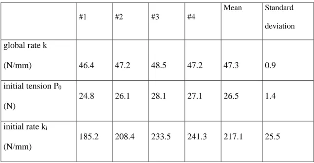
7 - the global rate k when the spring deflects fully (here from about 0.2 mm deflection)
- the initial tension P0, which is calculated as the ordinate at x=0 of the line fitting the
overall behavior
- the initial rate ki at the beginning of deflection when the coils are still in contact
The values obtained are detailed in Table 2.
Table 2: exploitation of the experimental results
#1 #2 #3 #4 Mean Standard deviation global rate k (N/mm) 46.4 47.2 48.5 47.2 47.3 0.9 initial tension P0 (N) 24.8 26.1 28.1 27.1 26.5 1.4 initial rate ki (N/mm) 185.2 208.4 233.5 241.3 217.1 25.5
The four springs showed similar values of their global rate, with an average value of 47.3
N/mm, which is close to but lower than the value given in the catalogue (50.4 N/mm).
The values of the initial tension were very close to that of the catalogue (26.2 N) and the
average experimental value of P0 was 26.5 N. We can also note that the transition load,
PT, between the initial behavior and the global behavior is greater than P0 (PT = 33.9 N
8 the initial tension. Nevertheless, the common rule for designers [24] induces a minimum
operating load of 51.2 N. This value appears to be very conservative as the spring shows
a linear load-deflection curve from PT = 33.9 N. The linear operating range of this spring
could reasonably be extended. We thus propose both FEA and analytical approaches to
better estimate the transition load, PT , of an extension spring.
3. SIMULATION OF THE AXIAL BEHAVIOR OF EXTENSION SPRINGS
3.1 SIMULATION PROCESS
3D Finite Element Analysis is commonly exploited to simulate the behavior of various
springs [1, 27-32]. This kind of simulation could not be directly used in our study
because, in the initial geometry of extension springs, the coils are in contact and that
could cause some nodes to be merged. Moreover, the initial tension could not be taken
into account easily. Alternatively, a simulation that integrates the shaping process of such
a spring would make it possible to integrate the problem of contact and preload.
Unfortunately, this would require a significant calculation time and would also require
exploiting elastic-plastic deformation laws for the material that are not given neither by
standards or wire manufacturers.
Known material properties are those of a 1.4310 stainless steel (EN 10270-3) and detailed
in table 3.
Table 3: elastic parameters used on the finite element simulation
Young Modulus (MPa) Poisson ratio Density (T/mm3)
9 To be able to simulate the initial tension, we adapted the simulation process suggested by
Shimoseki [19], which uses three-dimensional, two-nodal beam elements. In this work,
an extension spring is modeled by beam elements that fit the initial geometry of the
spring and the initial tension is not considered. Later in the book, gap conditions are
exploited to manage contact between coils in conical springs. We propose to combine the
two approaches so as to be able to simulate the initial tension.
Hence, the extension spring is first modeled with a body having an axial pitch smaller
than the wire diameter. The pitch value is determined depending on the required
transition load PT (remember that PT is greater than the initial tension P0) and the
deflection of one coil using the following formula:
p = d − 8 PG dT D43
(3) We can note that this pitch value is not only required to model the initial tension on the
FE model but is also the pitch that is defined on the coiling machine so as to manufacture
an extension spring with the appropriate initial tension. Until now, manufacturers had to
define the axial pitch of the body of extension springs with a trial and error process. As
far as we are aware, Eq. [3] is defined for the very first time and is thus of key interest for
saving time in the manufacturing process of extension springs.
Then gaps are defined by using connectors in Abaqus with a stop function when the
distance between nodes is equal to the wire diameter. One node of the upper loop is
pinned and radial displacements of a node of the opposite loop are set equal to 0. Details
10 simulation process (Fig. 4: initial), the spring exhibits a free length slightly lower than L0
and there is no pretension. The spring is then extended at step 1 so that the distance
between coils exceeds the wire diameter. Thus at the end of step 1, the length of the
spring is greater than L0. Then at step 2 the axial displacement previously set is
desactivated so that the length decreases, the connectors are activated and the preload is
set. At the end of step 2, the extension springs is preloaded (see Von Mises stress) and
has the required free length L0. On the next steps, an increasing axial load is applied in
order to obtain a realistic load/deflection curve even for load values lower than the initial
tension.
Fig 4. FEA of an extension spring with initial tension
The calculation time is less than 2 minutes on a using a laptop.
3.2 FEA RESULTS
The results of the simulation are presented in Fig. 5 and compared with the average
experimental results for better readability.
Fig 5. Load-deflection curve of an extension spring with initial tension, FEA
The finite-element simulation shows very good correlation with the average experimental
11 The FEA simulation also enables the behavior of the loops and the behavior of the body
to be analyzed separately. To analyze the behavior of the coils, the stiffness of the body is
artificially increased by taking the wire diameter to be 20 mm (instead of 1.4 mm) and, to
analyze the behavior of the body, the stiffness of the loops is artificially increased by
considering the wire diameter to be 20 mm. The results are presented in Fig. 5. We can
see the expected full linear load-deflection curve for the loops but we can also see that the
load-deflection curve of the body exhibits a bilinear curve with an initial rate inducing a
deflection of approximately 0.5 coils. This initial deflection of the body has to be
considered in an analytical approach to estimate the initial rate of extension springs.
4. ANALYTICAL STUDY
It is often of key interest for designers to be able to exploit analytical formulae instead of
having to perform FEA. Analytical formulae are also useful for researchers to obtain kick
evaluation processes for example in order to study dynamical issues in helical springs
[33, 34]. To determine the global stiffness of an extension spring, the loops and the body
can be studied separately.
4.1 STIFFNESS OF A CROSSOVER LOOP
In order to define the stiffness of a loop, it is first necessary to describe its geometry
precisely. Fig. 6 details the geometry of a crossover loop.
Fig 6. Detailed geometry of a crossover loop
12 1) a circular part linking the loop with the body and having a radius RL1,
2) a circular part of radius RL2 (commonly RL2 = D/2) at the end,
3) a linear part of length LL that links the two circular parts
For such geometry, Castigliano’s second theorem [35] can be employed, as done by Dym
for compression springs [22], to find the flexibility of a loop. It is obtained by adding the
flexibilities of the three parts:
( )
(
) (
)
2 2 2 1 1 1 1 1 1 1 1 1 0 1cos sin sin cos
1 L L L L L L L R R L R P R d GS GJ EI u P π θ θ θ θ θ + − + = + +
∫
( )
2 2 2 2(
2 2)
2 2 2 0 2 sin cos sin L L R P R d GS ES I u E P π θ θ θ θ = + + ∫
( )
2 3 2 0 1 2 L L L L u L x xL dx G P P S EI + − = + ∫
This induces: 3 2 2 1 2 1 1 3 2 2 4 4 2 L L L L L L L R L R R GJ EI R F = π + π − + L +π (4) with 4 64 d J =π ; 4 32 d I =π ; 1 2 L L D L = −R 4.2 GLOBAL STIFFNESSIt can be seen in Fig. 6 that the circular part with radius RL1 decreases the number of coils
of the body (that has the common helix shape). This decrease can be estimated by the
13 1 L r n D π ≈ (5)
Thus the common formula for an extension spring (Eq. 2) can be adapted to define the
flexibility of the remaining body:
( L) 3 4 8 n - 2n D F G d b = (6)
Eq. 4 and Eq. 6 can be combined to calculate the global rate of the spring, k:
1 2 b L k F F = + (7) 4.3 INITIAL STIFFNESS
At the beginning of deflection, the FEA analysis highlighted that the stiffness was due to
the deflection of the loops and the deflection of half a coil of the body. Thus, Eq. 2 and
Eq. 4 are combined to define the initial rate of the spring ki:
3 4 4 D G 1 2 d i L k F = + (8)
4.4 COMPARISON WITH EXPERIMENTAL DATA
Several analytical approaches can be presented to estimate the behavior of an extension
spring. For both models, P0 equals 26.5 N and the material properties lead to G =70000
14 The experimental mean values are compared with the results of three analytical
approaches: the common linear behavior with n active coils (k = 50.4 N/mm), the
common linear behavior with n +1 active coils (k = 42.0 N/mm) and the proposed
bi-linear behavior.
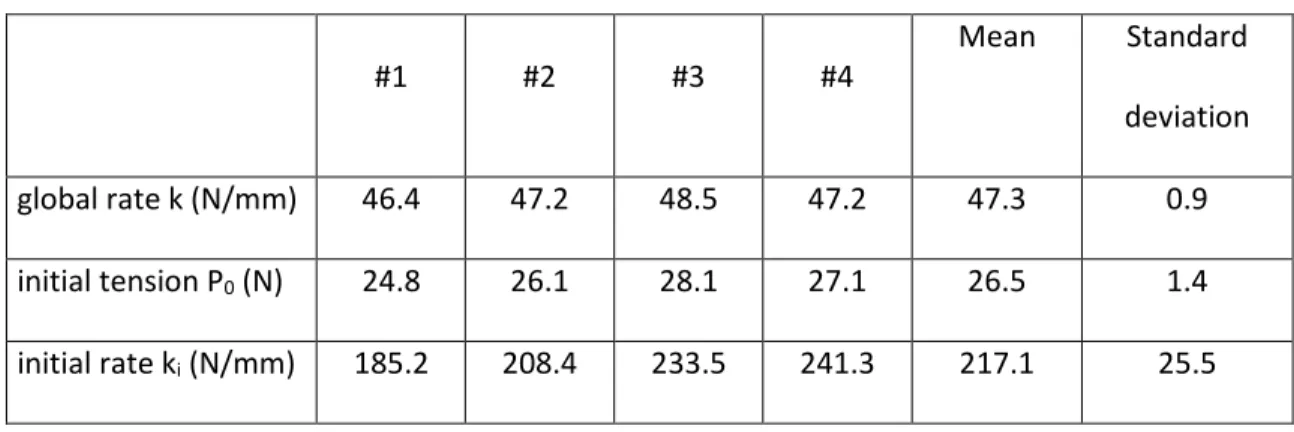
Table 4: experimental data
#1 #2 #3 #4 Mean Standard
deviation global rate k (N/mm) 46.4 47.2 48.5 47.2 47.3 0.9 initial tension P0 (N) 24.8 26.1 28.1 27.1 26.5 1.4
initial rate ki (N/mm) 185.2 208.4 233.5 241.3 217.1 25.5
For the bilinear approach, the flexibility of the loops requires RL1 to be defined. In the
example presented here, RL1 = 1.5 mm. This induces, k = 46.2 N/mm; ki = 231 N/mm.
The three analytical approaches are compared with the experimental results in Fig 7.
Fig 7. Load-deflection curve of an extension spring with initial tension, analytical
We can see that the proposed bilinear approach gives results that are very close to the
experimental ones. Thanks to the evaluation of the behavior of the loops, the global
stiffness of the bilinear model is more accurate than that found with the linear approaches
15 Moreover, the common operating range (20%-80% [24]) for this spring is between 51.2
N and 126 N. The proposed bilinear approach enables the transition to be estimated using
Eq. 9. 0 33.1i T i k P P N k k = = − (9)
Thus the lower bound of the operating range can be reduced (from 51.2 N to 33.1 N),
significantly increasing the potential operating range of the spring [6%-80%].
In addition, with this calculated value of PT it is possible for manufacturer to determine
the needed pitch on the coiling machine and to reduce set up time.
5. CONCLUSIONS
The global stiffness of extension springs is commonly calculated using the formula
dedicated to compression springs and two options are proposed for defining the active
coils na. The first one defines na as the number of coils of the body: na = n, and the second
one considers the influence of the loops by adding one coil: na = n +1. The aim of the
study was, first, to evaluate the accuracy of these formulae and propose new approaches
by performing experimental, finite-element and analytical analyses.
The experimental study clearly showed what is only suggested by standards: the initial
tension induces the extension spring to exhibit a bilinear load-deflection curve with high
stiffness at the beginning of deflection.
To analyze the behavior of extension springs in greater depth, a finite-element study was
then developed. As far as we are aware, this modeled the initial load of extension springs
16 the pretension. Simulations highlighted that the initial rate of the spring was due to the
deflection of the loops and about half a coil of the body. Thanks to these results, an
analytical approach was developed using Castigliano’s second theorem and a bilinear
behavior was thus modeled. This new model gives a more accurate evaluation of the
global stiffness of the extension spring. Moreover, it enables the transition load to be
evaluated (from the initial stiffness to the global stiffness). This transition load can
opportunely be exploited to enlarge the common operating range of extension springs,
which currently appears to be very conservative.
Finally, this study can also be directly exploited by manufacturers to quickly calculate the
pitch to be set on the coiling machine in order to obtain the expected initial tension on the
load-deflection curve, saving time on the manufacturing process.
Of course, it is important to bear in mind that this study was illustrated using a single
spring geometry. It can thus be considered as a first, but important, step in assessing the
quality of the analytical formulae concerning extension springs. Several studies (using
experimental/FEA/analytical approaches) were performed on springs having other
geometries and indicated the same conclusions but further investigations will be
necessary to fully cover the design space. It could also be interesting to analyze the stress
in the body and the stresses in the coils using 3D FEA in order to give a more accurate
estimate of the upper bound of the operating range of extension springs.
17 c spring index = D/d
d wire diameter
D mean diameter of the spring Do external diameter of the spring
E Young’s modulus G torsional modulus k global spring rate Ki initial spring rate
L0 free external length
LL length of the linear part of the loop
L1 length related to P1 L2 length related to P2
n number of coils of the body na number of active coils
P axial load
P0 initial tension load related to L0 P1 axial load related to L1
18 P2 axial load related to L2
PT axial transition load between the initial behavior and the global behavior
RL1 radius RL2 θ1 θ2 radius angle angle REFERENCES
[1] Bogard, F., Murer, S., Debray, K., Ning, Y., Bartkowiak, B., 2016, “FE optimization of the ejection force of a spring-maintained connector”, Mechanics & Industry, 17 - 605, 5p. Available online at: https://doi.org/10.1051/meca/2016002
[2] Dabrowski, L., Wasilczuk, M., 2004, “Influence of hydrostatic pump operation period on performance of a thrust bearing of a 125 MW pump-turbine”, Mechanics & Industry, 5 - 1, 3-9. Available online at:
https://doi.org/10.1051/meca:2004002
[2] Gosselin, C., 2006, “Adaptive Robotic Mechanical Systems: A Design Paradigm”, ASME J. Mech. Des., 128, 192-198. Available online at:
19 [3] Rone, W.S., Saab, W., Ben-Tzvi, P., 2018, “Design, Modeling, and Integration of a Flexible Universal Spatial Robotic Tail”, ASME J. Mechanisms Robotics 10(4),
041001. Available online at: http://dx.doi.org/10.1115/1.4039500.
[4] Yang, Z.W., Lan, C-C., 2015, “An adjustable gravity-balancing mechanism using planar extension and compression springs”, Mechanism and Machine Theory 92,
314–329. Available online at:
http://dx.doi.org/10.1016/j.mechmachtheory.2015.05.006.
[5] Lopez-Martinez, J., Garcia-Vallejo, D., Arrabal-Campos, F-M., Garcia-Manrique, J-M. , 2018, “Design of Three New Cam-Based Constant-Force Mechanisms”, ASME J. Mech. Des 140(8), 082302. Available online at:
http://dx.doi.org/10.1115/1.4040174.
[6] Martini, A., Troncossi, M., Carricato, M., and Rivola, A., 2014, “Static Balancing of a Parallel Kinematics Machine With Linear-Delta Architecture”, ASME 12th Biennial Conference on Engineering Systems Design and Analysis, Paper No. ESDA2014-20449, pp. V003T17A010 Available online at:
http://dx.doi.org/10.1115/ESDA2014-20449.
[7] Barents, R., Schenk, M., van Dorsser, W.D., Wisse, B. M. and Herder, J.L., 2011, “Spring-to-Spring Balancing as Energy-Free Adjustment Method in Gravity Equilibrators”, ASME J. Mech. Des., 133(6), 061010. Available online at:
20 [8] Piovesan, D. and Alladi, P., 2016, “Analysis of an Energy Saving Ratchet-Based
Ankle Exoskeleton”, ASME 2016 International Design Engineering Technical Conferences and Computers and Information in Engineering Conference, Paper No. DETC2016-60137, pp. V003T11A012. Available online at:
http://dx.doi.org/10.1115/DETC2016-60137.
[9] Yeow, C.-H., Baisch, A.T., Talbot, S.G., Walsh, C.J., 2014, “Cable-Driven Finger Exercise Device With Extension Return Springs for Recreating Standard Therapy Exercises”, ASME J. Med. Dev., 8, 014502. Available online at:
http://dx.doi.org/10.1115/1.4025449.
[10] Olesnavage, K. and Winter, A., 2016, “Design and Preliminary Testing of a
Prototype for Evaluating Lower Leg Trajectory Error as an Optimization Metric for Prosthetic Feet”, ASME 2016 International Design Engineering Technical
Conferences and Computers and Information in Engineering Conference, Paper No. DETC2016-60565, pp. V05AT07A038. Available online at:
http://dx.doi.org/10.1115/DETC2016-60565.
[11] Spring Manufacturers Institute, Inc., 2001 Midwest Road, Suite 106, Oak Brook, Illinois 60523-1335 USA, www.smihq.org
[12] The Institute of Spring Technology, Henry Street, Sheffield. S3 7EQ, United Kingdom, www.ist.org.uk/index.html
[13] http://www.planetspring.com
21 [15] Wahl, A. M., 1963, Mechanical Springs, McGraw-Hill Book Company, New York. [16] Shirurkar, A., Patil, Y. and Jebaseelan, D.D., 2018, “Reliability improvement of fork
biasing spring in MCCB mechanism“, Elsevier Int J Syst Assur Eng Manag (2018). https://doi.org/10.1007/s13198-018-0732-y
[17] Gluck, J.V., 1982, “Fatigue of Small Helical Extension Springs Subjected to Static Torsion and Alternating Lateral Deflection”, J. Eng. Mater. Technol 104(3),
180-185. Available online at: http://dx.doi.org/10.1115/1.3225062.
[18] Rodriguez, E., Paredes, M, Sartor, M., 2004, “Optimisation Methods for Compression, Extension and torsion spring Design”, International conference IDMME, Bath.
[19] Shimoseki, M., Hamano, T., Imaizumi, T., 2003, “FEM for springs”, Springer, ISBN 978-3-540-00046-4
[20] Rodriguez, E., Paredes, M., Sartor, M., 2006, “Analytical Behavior Law for a Constant Pitch Conical Compression Spring”, ASME J. Mech. Des., 129, pp
1352-1356.
[21] Paredes, M., 2013, “Analytical and Experimental Study of Conical Telescoping Springs With Nonconstant Pitch”, ASME J. Mech. Des., 135, 094502. Available
online at: http://dx.doi.org/10.1115/1.4024721
[22] Dym, C., 2009, “Consistent Derivations of Spring Rates for Helical Springs”, ASME J. Mech. Des., 131. Available online at: http://dx.doi.org/10.1115/1.3125888.
22 [24] IST, 1980–2005, “Essential Spring Design Training Course,” Handbook, The Institute
of Spring Technology, Sheffield, United Kingdom.
[25] Stainless steel for mechanical springs, 2001, NF EN 10270-3, ISSN 0335-3931. [26] http://www.andilog.com/springtest-manual-spring-tester.html?category_id=14 [27] Verotti, M., Crescenzi, R., Balucani, M., Belfiore, N., 2015, “MEMS-Based Conjugate
Surfaces Flexure Hinge”, ASME J. Mech. Des., 137, 012301. Available online at:
http://dx.doi.org/10.1115/1.4028791.
[28] Thiebaud, F. Ben Zineb, T., 2014, “Experimental and finite element analysis of superelastic behaviour of shape memory alloy for damping applications”, Mechanics & Industry, 15, 371-376. Available online at:
https://doi.org/10.1051/meca:2014040.
[29] Carpino, G., Accoto, D., Sergi, F., Tagliamonte, N. L., Guglielmelli, E., 2012, “A Novel Compact Torsional Spring for Series Elastic Actuators for Assistive Wearable
Robots”, ASME J. Mech. Des., 134, 121002. Available online at:
http://dx.doi.org/10.1115/1.4007695.
[30] Koay, L. K., Gitani-Briggs, H., 2011, “Design and Optimization of Mechanically Resonant Torsional Spring Mechanism for Laser Light Dispersion Applications”, ASME J. Mech. Des., 133, 014504. Available online at:
23 [31] Vehar Jutte, C., Kota, S., 2010, “Design of Single, Multiple, and Scaled Nonlinear
Springs for Prescribed Nonlinear Responses”, ASME J. Mech. Des., 132, 011003.
Available online at: http://dx.doi.org/10.1115/1.4000595.
[32] Vehar Jutte, C., Kota, S., 2008, “Design of Nonlinear Springs for Prescribed Load-Displacement Functions”, ASME J. Mech. Des., 130, 081403. Available online at:
http://dx.doi.org/10.1115/1.2936928.
[33] Hamza, A., Ayadi, S., Hadj-Taieb, E., 2013, “Resonance phenomenon of strain waves in helical compression springs”, Mechanics & Industry, 14, 253-265.
Available online at: https://doi.org/10.1051/meca:2013069
[34] Ayadi, S., Hadj-Taieb, E., 2006, “Influence des caractéristiques mécaniques sur la propagation des ondes de déformations linéaires dans les ressorts hélicoidaux”, Mechanics & Industry, 7, 551-563. Available online at:
https://doi.org/10.1051/meca:2007012
[35] Dym, C. L., and Shames, I. H., 1973, Solid Mechanics: A Variational Approach, McGraw-Hill, New York.