UNIVERSITÉ DE MONTRÉAL
THREE-DIMENSIONAL MICROSTRUCTURES OF EPOXY-CARBON
NANOTUBE NANOCOMPOSITES
ROUHOLLAH DERMANAKI FARAHANI
DÉPARTEMENT DE GÉNIE MÉCANIQUE
ÉCOLE POLYTECHNIQUE DE MONTRÉAL
THÈSE PRÉSENTÉE EN VUE DE L’OBTENTION
DU DIPLÔME DE PHILOSOPHIAE DOCTOR
(GÉNIE MÉCANIQUE)
NOVEMBRE 2011
UNIVERSITÉ DE MONTRÉAL
ÉCOLE POLYTECHNIQUE DE MONTRÉAL
Cette thèse intitulée:
THREE-DIMENSIONAL MICROSTRUCTURES OF EPOXY-CARBON
NANOTUBE NANOCOMPOSITES
présentée par: DERMANAKI FARAHANI Rouhollah
en vue de l’obtention de diplôme de : Philosophiae Doctor
a été dûment acceptée par le jury d’examen constitué de :
Mme. ROSS Annie, Ph. D., présidente
M. THERRIAULT Daniel, Ph. D., membre et directeur de recherche
M. LÉVESQUE Martin, Ph. D., membre et codirecteur de recherche
M. BOUKHILI Rachid, Ph. D., membre
DEDICATIONS
To my mother; for her emotional supports!
ACKNOWLEDGEMENTS
I wish to thank all those who supported me in the completion of this study and made the way of research smooth for me.
First of all, I would like to convey my gratitude to my advisors, Professor Daniel Therriault and Professor Martin Lévesque, who provided me with fundamental advises. They always supported me very well in my research with availability, patience and encouragement. I am very grateful for the things that I learnt from them; not only the scientific matters, but also lots of knowledge which are very helpful in all aspects of my life. It had been a true privilege to learn from such competent and sincere supervisors.
I also gratefully thank our collaborators at Institut National de la Recherche Scientifique, INRS-Énergie, Matériaux et Télécommunications, especially Professor My Ali El Khakani and Dr. Barhim Aissa for their valuable advises and for providing single-walled carbon nanotubes and their characterizations.
I owe special gratitude to the members of Laboratory for Multiscale Mechanics (LM2) research group who made the working place a fascinating area. My especial thanks are due to Dr. Hamid Dalir for his sympathy, support and many things that I have learnt from him. I would like to thank Dr. Louis Laberge Lebel for his great kindness to help me in the first year of my study.
I like to extent my thanks to the entire technical and administrative staff of the Mechanical Engineering Department at École Polytechnique de Montréal.
I would like to acknowledge financial support from FQRNT (Le Fonds Québécois de la Recherche sur la Nature et les Technologies).
I would also like to send a heartfelt acknowledgment to my friends who made all these years vey joyful with interesting, intellectual and creative ideas. Habib, Maryam, Farhad, Hadi, Hamid, Navid, Ebrahim, Hassan, Behzad …
Finally I could not have accomplished this without all the supports of my family, especially my lovely wife. They are the driving force behind all of my successes. To them I tribute a fervent thanks.
RÉSUMÉ
Dans les dernières décennies, la communauté scientifique a réalisé des efforts considérables dans le but d’avancer dans les domaines de la micro- et nanotechnologies. Cela est dû au grand potentiel de ces technologies dans une large variété d'applications, allant des composites structuraux jusqu’aux systèmes microélectromécaniques (MEMS) et à l'électronique organique. Pour de telles applications, les nanocomposites à base de polymères renforcés par des nanotubes de carbone (CNTs), plus spécifiquement les nanotubes de carbone à paroi simple, représentent un matériau prometteur grâce à ses propriétés mécaniques et électriques lorsque comparé aux résines conventionnelles. Toutefois, plusieurs défis quant au traitement et à la fabrication du nanomcomposite doivent être adressés dans l'objectif d'augmenter l'efficacité de ces nanocomposites. La production de nanotubes de carbone de haute qualité ayant un grand rapport de forme, leur dispersion dans la matrice polymère ainsi que l'amélioration de l'adhésion à l’interface sont tous des paramètres importants dans le comportement mécanique et électrique des nanocomposites. Ces paramètres pourraient être ingénieusement établis afin d'obtenir des propriétés optimales pour les micro- et macro- applications du nanocomposite. Cependant, la miniaturisation et l'optimisation des formes tridimensionnelles des systèmes en nanocomposite sont loin de leur plein potentiel, partiellement à cause du manque des techniques de fabrication adéquates.
Cette thèse présente le développement des matériaux nanocomposites pour la fabrication de microstructures tridimensionnelles (3D) en utilisant les techniques de l'écriture-directe (DW), la micro-infiltration et l'écriture directe assistée par rayonnement UV (UV-DW). La thèse adresse deux parties principales: la préparation du nanocomposite et la fabrication des structures 3D de nanocomposites. Des nanotubes de carbone à paroi simple de haute qualité ont été produits par la
méthode d'ablation lazer UV pour ensuite subir une purification chimique. En utilisant un surfactant, une fonctionnalisation non-covalente a été réalisée sur la surface des nanotubes afin d'avoir une interaction additionnelle avec la matrice polymère. Différentes stratégies de mélange ont été utilisées pour aboutir à une meilleure dispersion des nanotubes de carbone dans la matrice d'époxy tel que le brassage, l'ultrasonication et le mélange par cisaillement élevé. Une autre étape de fonctionnalisation, cette fois avec des bio-molécules, a été aussi réalisée sur la surface des nanotubes pour améliorer encore plus les propriétés des nanocomposites. Des observations par microscopie optique et microscopie électronique à balayage ont révélé que ces bio-molécules ont amélioré la dispersion des nanotubes de carbone dans la matrice. La caractérisation mécanique a démontré une amélioration considérable dans la résistance (76%) et le module de rigidité (93%) du nanocomposite par rapport à l'époxy dans son état pur, et ce en ajoutant seulement 1% massique de nanotubes de carbone bio-fonctionnalisés.
Dans la deuxième partie de la thèse, des techniques de fabrication ont été utilisées afin de façonner sur mesures les propriétés effectives des microstructures 3D du nanocomposite. Premièrement, la méthode d'écriture directe et celle de la micro-infiltration ont été utilisées pour fabriquer des microstructures 3D de poutrelles en nanocomposites. Les propriétés statiques et dynamiques des poutrelles ont été obtenues en prenant avantage du positionnement et de l'orientation 3D des nanotubes de carbone. Les poutrelles à matrice époxy avec un squelette 3D de microfibres en nanocomposite ont été fabriquées en infiltrant le nanocomposite renforcé par les nanotubes dans un réseau microfluidique tridimensionnel de canaux poreux. L'efficacité de cette approche a été étudiée systématiquement en utilisant différentes résines d'époxy. Les propriétés dépendant de la température de ces poutrelles sont différentes des propriétés individuelles de leurs constituants. La squelette des microfibres a été conçu pour offrir une
meilleure performance face à une sollicitation de flexion en positionnant les microfibres dans les régions subissant les plus hauts niveaux de contraintes.
Par la suite, le mélange de nanocomposite a été injecté dans le réseau de canaux poreux sous deux différents niveaux de pression, obtenant ainsi deux niveaux de cisaillement différents lors de l'injection. Ceci a été réalisé dans l'objectif d’aligner les nanotubes dans les microfibres des poutrelles. Des études morphologiques et des observations de microsocopie électronique à transmission ont révélé que les nanotubes sont partiellement alignées dans les canaux microfluidiques selon la direction du flux et ce pour le cas où la plus grande valeur de pression est appliquée. Les mesures de rigidité ont été comparées avec les prédictions théoriques d'un modèle micromécanique. Considérant la faible fraction massique des nanotubes (~0.2 %), les nanotubes de carbone et leur alignement partiel ont causé une amélioration considérable de la rigidité lorsque comparé avec l'époxy pur. Basé sur les résultats expérimentaux et théoriques, la méthode de fabrication présentée aide à aligner les nanotubes de carbone dans le nanocomposite grâce du flux de cisaillement et du confinement dimensionnel dans les canaux microfluidiques.
Le dernier point étudié dans la présente recherche est l'utilisation de la méthode d'écriture directe assistée par UV pour la fabrication de formes auto-portantes de nanocomposites destinées à des capteurs de déformation. La complexité des capteurs produits démontre les larges possibilités de la méthode de fabrication lorsque comparé à la méthode conventionnelle de la photolithographie. La sensibilité électromécanique du capteur a été évaluée en corrélant la résistivité mesurée aux déplacement/déformations appliqués. Des mesures de conductivité électrique révèlent que les capteurs produits sont très sensibles aux petites perturbations mécaniques, surtout lorsqu'on compare la sensibilité avec des faibles fractions de nanotubes aux capteurs traditionnels en métaux ou aux capteurs à base de films de nanocomposite.
Les procédures de préparation des nanocomposites présentées ici : la purificication des nanotubes, la fonctionnalisation non covalente, la bio-fonctionnalisation et la stratégie de mélange des nanocomposites aident à développer des nanocomposites de haute performance et étendre leurs applications et leurs fonctionnalités. Les dispositifs conûs dans le présent travail offrent une nouvelle perspective quant à la fabrication des microstructures 3D de nanocomposites et ce pour une large gamme d'applications tel que l'électronique organique, les capteurs de déformations à très haute sensibilité ainsi que d'autres applications dans le domaine aérospatial.
ABSTRACT
Over the last few decades, worldwide increasing effort has been directed towards achieving advances in micro- and nanotechnologies. This is motivated by their high potential for a wide variety of technological applications, ranging from structural composites to micro electromechanical systems (MEMS) and organic electronics. For such applications, polymer nanocomposites reinforced with carbon nanotubes (CNTs), and more specifically single-walled carbon nanotubes (SWCNTs), are promising materials compared to conventional resins due to their interesting mechanical and electrical properties. However, several fundamental processing and fabrication challenges have to be addressed in order to effectively use these nanocomposites. Production of high quality carbon nanotubes (CNTs) having large aspect ratio, their proper dispersion in polymer matrices as well as the improvement of interfacial bonding are the main parameters affecting their mechanical and electrical performance. Moreover, these materials can be engineered to deliver optimal properties for micro- and macro-devices. However, device miniaturization and three-dimensional shape optimization have not reached their full potential, partly because of the lack of suitable manufacturing techniques.
This thesis reports the development of nanocomposite materials for the fabrication of three-dimensional (3D) microstructures with direct-write (DW), micro-infiltration and UV-assisted direct-write (UV-DW) techniques. The thesis focuses on two main parts; nanocomposite preparation and nanocomposite-based 3D microstructures fabrication. High-quality SWCNTs were produced by the UV-laser ablation method and then subjected to a chemical purification. A non-covalent functionalization with a surfactant was performed for additional interaction with the matrix. Different mixing strategies including stirring, ultrasonication and high shear mixing were used to properly disperse SWCNTs within an epoxy matrix. Subsequent functionalization
with biomolecules was also applied on the nanotubes surface for improving further the nanocomposites properties. Optical and scanning electron microscope observations revealed that the biomolecules improved the nanotube dispersion into the epoxy matrix. Mechanical characterization showed that nanocomposites demonstrated considerable enhancement in both strength (by 76%) and modulus (by 93%), with respect to the bulk epoxy, with the addition of only 1 wt% of biofunctionalized-SWCNTs.
In the second part of this thesis, a few fabrication techniques have been used to tailor the overall properties of 3D microstructures. First, the DW and micro-infiltration techniques were employed to manufacture a 3D-reinforced nanocomposite. The dynamic and static mechanical properties of the beams were successfully tailored by taking advantage of nanotubes 3D positioning and orienting. To this end, epoxy composite beams reinforced with a complex nanocomposite microfibers 3D skeleton were fabricated via the micro-infiltration of carbon nanotube nanocomposites into a 3D porous microfluidic network. The effectiveness of this manufacturing approach was systematically studied by using different epoxy resins. The temperature-dependent mechanical properties of these multifunctional beams showed different features than their individual constituents. The microfibers 3D pattern was adapted to offer better performance under flexural solicitation by positioning most of the reinforcing microfibers in higher stress regions.
Subsequently, the nanocomposite suspensions were injected into the empty networks under two different controlled and constant pressures for subjecting the suspensions to different shear conditions. This procedure was performed in an attempt to control the nanotubes orientations into the 3D-reinforced beams. Morphological studies and transmission electron microscopy (TEM) observation revealed that the SWCNTs were preferentially aligned in the microchannels
along the flow direction at the higher injection pressure. The 3D-reinforced beams stiffness was compared with the theoretically predicted values obtained from a micromechanical model. Given the very low amount of nanotube added (~0.2 wt.%), the nanotubes orientation led to a considerable increase (~14%) of the nanocomposite’s stiffness when compared to the neat epoxy. Based on the experimental and theoretical results, the present manufacturing technique enables the spatial orientation of nanotubes in the final product by taking advantage of shear flow combined with dimensional constraining inside the microfluidic channels.
The final point studied in this research was to use the UV-DW technique for the fabrication of 3D freestanding patterned nanocomposite strain sensors. The complexity of the manufactured sensors demonstrated the high capability of the technique when compared to conventional photolithographic technologies. The sensors electromechanical sensitivities were evaluated by correlating their measured resistivities to the applied displacements/strains. Electrical conductivity measurements revealed that the manufactured sensors are highly sensitive to small mechanical disturbances, especially for lower nanotube loadings when compared to traditional metallic or nanocomposite films.
The nanocomposite preparation procedures presented here, i.e., the nanotube purification, non-covalent functionalization, biofunctionalization and nanocomposite mixing strategies, helps toward the development of high-performance nanocomposite materials and extends their application to functional devices. The devices manufactured in this work provided a new perspective for manufacturing 3D-reinforced nanocomposite microstructures for a broad range of application such as organic electronics, highly sensitive 3D freestanding microstructured sensors and aerospace.
TABLE OF CONTENTS
DEDICATIONS ... iii
ACKNOWLEDGEMENTS ... iv
RÉSUMÉ ... vi
ABSTRACT ... x
TABLE OF CONTENTS ... xiii
LIST OF TABLES ... xx
LIST OF FIGURES ... xxii
LIST OF ABBREVIATIONS ... xxx
LIST OF APPENDICES ... xxxii
INTRODUCTION AND THESIS OBJECTIVE ... 1
CHAPTER 1: Literature review... 5
1.1. Carbon nanotubes ... 5
1.1.1. Carbon nanotube structural characteristics ... 5
1.1.2. Carbon nanotube properties ... 7
1.1.3. Carbon nanotubes production methods ... 9
1.2. Carbon nanotubes-polymer nanocomposites ... 10
1.2.1. Mechanical reinforcement ... 11
1.2.1.1.Aspect ratio ... 11
1.2.1.3.Alignment ... 12
1.2.1.4.Interfacial interaction ... 13
1.2.2. Electrical conductivity ... 14
1.2.3. Nanocomposite preparation methods using thermosetting matrices ... 16
1.2.3.1.Nanotube purification ... 17
1.2.3.2.Nanotube surface treatment ... 18
1.2.3.3.Mixing in solution method ... 21
1.2.3.4.High shear mixing methods ... 22
1.2.4. Nanocomposite bulk properties ... 24
1.2.4.1.Mechanical properties ... 24
1.2.4.2.Electrical conductivity ... 27
1.2.5. Orientation of CNTs ... 28
1.2.6. Rheological behavior of nanocomposites with thermosetting matrices ... 30
1.3. Fabrication of 3D nanocomposite microstructures ... 31
1.3.1. Microfabrication techniques ... 32
1.3.2. Direct-write (DW) techniques ... 33
1.3.3. Photopolymers in microfabrication... 35
1.3.4. UV-assisted direct-write technique ... 37
1.4. CNT-based nanocomposites for sensing applications ... 39
2.1. Scientific approach and organization of research work ... 42
2.2. Article presentation and coherence with research objectives ... 43
2.2.1. Manufacturing 3D-reinforced beams with the micro-infiltration technique: Chapter 3-4 (Articles 1-2)... 3-43-4
2.2.2. Manufacturing 3D freestanding nanocomposite microstructures with the UV-DW technique: Chapter 5-6 and appendix A and B (Articles 3-4 and proceeding papers, Appendices) ... 45
CHAPTER 3: Article 1: Micro-infiltration of three-dimensional porous networks with carbon nanotube-based nanocomposite for material design ... 48
Abstract ... 48
3.1. Introduction ... 49
3.2. Experimental ... 51
3.2.1. Nanocomposite preparation ... 51
3.2.2. Fabrication of 3D microfluidic networks ... 52
3.2.3. Preparation of the 3D-reinforced beams via micro-infiltration technique ... 55
3.2.4. Morphological and mechanical characterization ... 58
3.3. Results and discussion ... 59
3.3.1. Carbon nanotube structural characterization ... 59
3.3.2. Morphological characterization ... 60
3.3.3. Mechanical characterizations ... 63
3.3.3.2.Quasi-static three-point bending ... 66
3.3.3.3.Tensile testing ... 69
3.4. Conclusion ... 70
3. Acknowledgments... 71
3. References ... 72
CHAPTER 4: Article 2: Flow-induced orientation of functionalized single-walled carbon nanotubes embedded in epoxy using three-dimensional microfluidic networks ... 76
Abstract ... 76
4.1. Introduction ... 77
4.2. Experimental ... 79
4.2.1. Materials ... 79
4.2.2. Preparation of nanocomposites ... 80
4.2.3. Micro-injection of 3D microfluidic networks ... 80
4.2.4. Nanotube and nanocomposites morphological characterizations ... 82
4.2.5. Viscosity characterization ... 83
4.2.6. Mechanical properties ... 85
4.3. Mechanical modeling ... 85
4.4. Results and discussion ... 90
4.4.1. Nanotube and nanocomposite morphological characterizations ... 90
4.4.3. Morphological characterization of the 3D-reinforced beams ... 96
4.4.4. Mechanical properties ... 98
4.4.5. Stiffness prediction with homogenization model ... 102
4.5. Conclusion ... 104
4. Acknowledgments... 105
4. Appendix 4.A ... 106
4. References ... 107
CHAPTER 5: Article 3: Biotin-streptavidin interactions in functionalized carbon nanotube-epoxy composites ... 110
Abstract ... 110
5.1. Introduction ... 111
5.2. Experimental details ... 114
5.2.1. SWCNTs synthesis, purification and biofunctionalization ... 114
5.2.2. SWCNTs characterization ... 116
5.2.3. Nanocomposite preparation ... 116
5.2.4. Nanocomposite morphological characterization... 117
5.2.5. Nanocomposite electrical and mechanical characterizations ... 118
5.3. Results and Discussion ... 119
5.3.1. Nanotube structural characterization ... 119
5.3.3. Mechanical properties ... 123
5.3.4. Governing interaction mechanisms... 126
5.3.5. Electrical conductivity ... 128
5.4. Conclusions ... 129
5. Acknowledgements ... 130
5. References ... 130
5. Table of contents entry: ... 133
CHAPTER 6: Article 4: Direct-write fabrication of freestanding nanocomposite strain sensors ... 134
Abstract ... 134
6.1. Introduction ... 135
6.2. Experimental Details ... 137
6.2.1. Nanocomposite preparation and characterization ... 137
6.2.2. Fabrication of the sensors and their characterizations ... 139
6.3. Results and discussions ... 141
6.3.1. Carbon nanotube characterization... 141
6.3.2. Nanocomposite viscosity characterizations ... 143
6.3.3. Sensors electromechanical sensitivity ... 144
6.3.3.1. Microfibers coupon ... 144
6.4. Conclusions ... 150
6. Acknowledgements ... 150
6. References ... 151
CHAPTER 7: General Discussion ... 153
7.1. Incorporation of CNT into the epoxy matrix ... 153
7.2. 3D-reinforced composites fabricated by micro-infiltration technique ... 155
7.3. 3D nanocomposite microstructures fabricated by UV-DW ... 157
CHAPTER 8 - Conclusion and recommendations... 159
REFERENCES ... 163
LIST OF TABLES
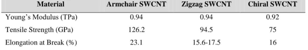
Table 1.1 Mechanical properties comparison of three different structures of single-walled carbon
nanotubes (Sinnott and Andrews 2001; Chae and Kumar 2006). ... 7
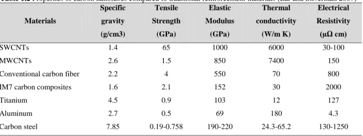
Table 1.2 Properties of carbon nanotubes compared to traditional reinforcement materials (Ear
and Silverman 2007) ... 8
Table 1.3 Mechanical properties enhancement of the nanocomposites reinforced with
functionalized SWCNTs ... 25
Table 1.4 Dynamic mechanical properties of epoxy-based nanocomposites reinforced with
SWCNTs ... 26
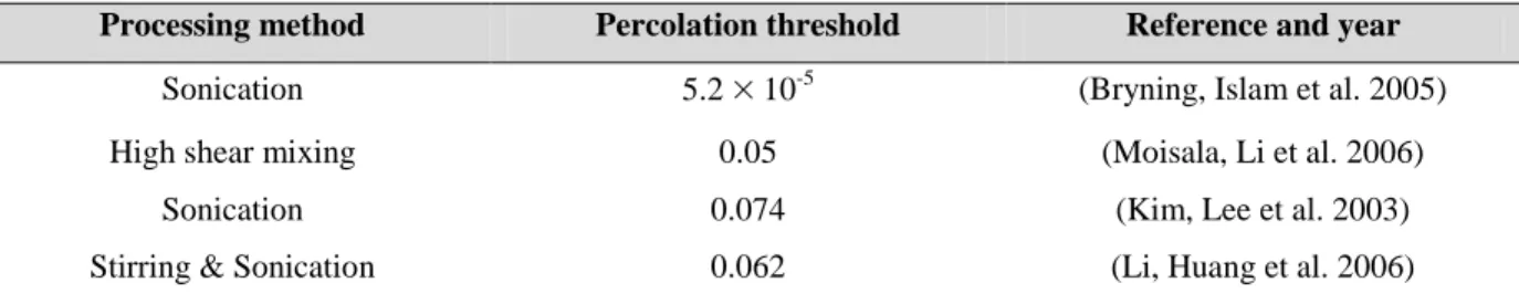
Table 1.5 Percolation concentration threshold achieved for some SWCNT-polymer composites
... 27
Table 3.1 Different types of 3D-reinforced beams, prepared in this study, and their components.
... 57
Table 3.2 Glass transition temperature (Tg) and storage modulus at 25°C for the 3D-reinforced
beams and the bulk epoxies. The E variation for the three different types of nanocomposite-infiltrated beams compared to their corresponding neat epoxy-infiltrated beams is presented in the last column. ... 66
Table 3.3 Comparison of increase of storage modulus at 25°C by adding SWCNTs to epoxy
matrices achieved in our work with those reported in literature. ... 66
Table 3.4 Flexural properties in three-point bending test for the 3D-reinforced beams and the
bulk epoxies. The variation of the properties for the two different types of nanocomposite-infiltrated beams from their corresponding neat epoxy-infiltrated beams is also presented. ... 69
Table 3.5 Tensile properties of the 3D-reinforced beams and the bulk epoxies. The second and
forth columns present the variation of the tensile properties of the two different nanocomposite-infiltrated beams from their corresponding neat epoxy-infiltrated beams. The last column lists the results obtained from rules of mixtures for each type of the infiltrated beams. ... 70
Table 4.1 Values of P and Q and the corresponding orientations. ... 88 Table 4.2 Estimation of the process-related apparent viscosity and the process-related apparent
shear rate in microfluidic network. ... 95
Table 4.3 Mechanical properties of the resin-injected and the nanocomposite-injected beams
prepared by micro-injection of the materials at two different shear rates and bulk epoxies. ... 101
Table 4.4 Comparison of increase of storage modulus at 25°C by adding SWCNTs to epoxy
matrices achieved in our work with those reported in literature. ... 103
Table 4.5 Analytical Young’s modulus of the resin- and NC-based microfibers with aligned,
partially aligned and randomly oriented CNTs. ... 104
Table 4.6 Analytical and experimental Young’s modulus of the resin- and NC-injected beams
with aligned, partially aligned and randomly oriented CNTs. ... 104
Table 5.1 Comparison of the mechanical properties improvements in our work with those
reported in literature. ... 126
Table 6.1 Electrical conductivity changes for the microfibers under applied strains. ... 147 Table 6.2 Electrical conductivity changes for the microsprings network under applied
LIST OF FIGURES
Figure 1.1 Three different structures of single-walled carbon nanotubes, a) armchair, b) zigzag
and c) chiral that represents different mechanical properties and electrical conductivity (Hui, Chipara et al. 2004). ... 6
Figure 1.2 Schematic of the laser ablation method for the fabrication of SWCNTs using a laser
beam which is pointed at a target of a graphite-Co-Ni mixture in a furnace at 1100˚C in an Argon atmosphere (Braidy, El Khakani et al. 2002) ... 10
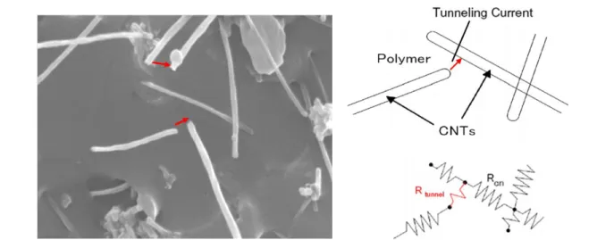
Figure 1.3 SEM image and schematic of possible tunnelling effect among CNTs in the
nanocomposite (Hu, Karube et al. 2008) ... 15
Figure 1.4 SEM image and schematic of CNTs percolation pathways in the nanocomposite (Li,
Chen et al. 2008) ... 15
Figure 1.5 Topographic AFM images of SWCNT networks (a) before and (b) after 14 h of 3 M
HNO3 reflux treatment. The breakage of SWCNTs after HNO3 reflux treatment is
observed (Dumitrescu, Wilson et al. 2007). ... 19
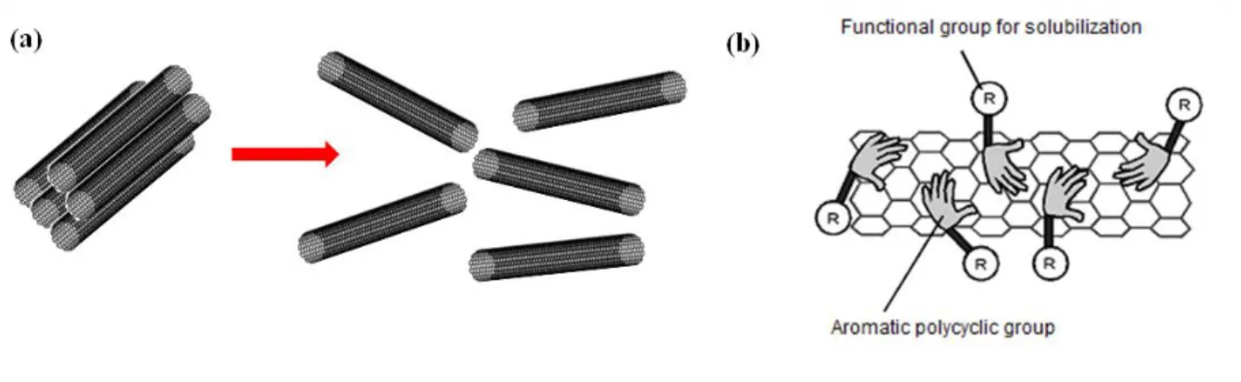
Figure 1.6 Schematic illustration of the procedure for solubilizing SWCNTs using porphyrins.
The use of porphyrins as surfactants leads to (a) deagglomeration of nanotube bundles and (b) surface functionalization of CNTs due to carboxyl functional groups (R) (Nakashima and Fujigaya 2007). ... 20
Figure 1.7 Schematic representation of (a) high shear mixing in three-roll mixer and (b) region
of high shear mixing between the feed and center rolls. The materials must pass through the small gap between the cylinders closely located to each other. The rolls with different speeds and different rotating directions provide high shear forces which is able to disperse nanotubes into the matrix (Thostenson and Chou 2006). ... 23
Figure 1.8 TEM micrographs of thin sections of PC/5 wt% MWCNT nanocomposites prepared
along the flow direction (a) at low shear rate and (b) at high shear rate (Abbasi, Carreau et al. 2010) ... 29
Figure 1.9 Microscopic images of CNTs nanocomposites (0.035 wt% MWNCT suspensions): a)
random orientation of CNTs and b) shear alignment of at shear rate of 10 s−1 (CNTs at very low fraction, 0.035 wt%, were aligned even after a small amount of shear was applied) (Rahatekar, Koziol et al. 2006) ... 30
Figure 1.10 Variation of apparent viscosity as a function of shear rate for a pure epoxy matrix
and epoxy suspensions containing different wt% of CNT (Rahatekar, Koziol et al. 2006) ... 31
Figure 1.11 Schematic illustration of the fabrication of 3D scaffold by direct-write method: a)
deposition of fugitive ink; b) ink layers after deposition; c) encapsulation with epoxy; d) resin solidification; and e) 3D microchannels after the ink removal (Therriault, Shepherd et al. 2005). ... 34
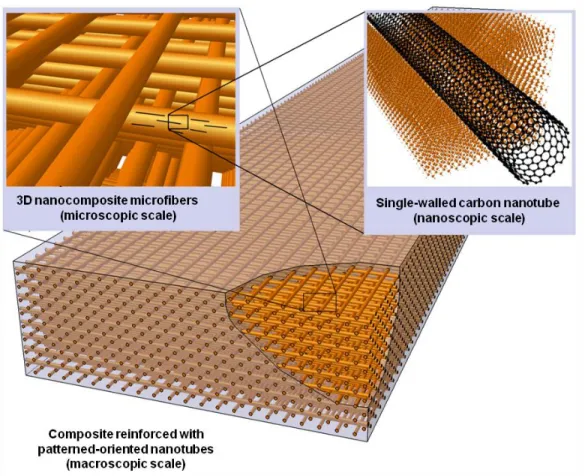
Figure 1.12 Schematic of a 3D-reinforced beam. An epoxy matrix is reinforced with nanotube
nanocomposite microfibers located three-dimensionally using an infiltration technique (reproduced from (Laberge Lebel 2009). ... 35
Figure 1.13 3D Microstructures made of photopolymers manufactured with (a) and (b)
stereolithography photopolymerization) (Liska, Schuster et al. 2007) and (c) and (d) two-photon absorption and two-photon absorption (Kawata, Sun et al. 2001). ... 37
Figure 1.14 Schematic illustration of UV-assisted direct-write method for the fabrication of the
nanocomposite micro-coils. The UV-curable nanocomposite was extruded using a controlled-robot through a needle (Lebel, Aissa et al. 2010) ... 38
Figure 1.15 Schematic and real image of a nanocomposite strain sensor under tensile strain (Hu,
Yin et al. 2011) ... 40
Figure 2.1 Schematic of two microfabrication approaches used to manufacture 3D
nanocomposite microstructures ... 42
Figure 3.1 Schematic representation of the manufacturing process of a 3D-reinforced
nanocomposite beam through micro-infiltration of 3D microfluidic network: (a) deposition of fugitive ink scaffold on an epoxy substrate, (b) encapsulation of the 3D ink-based scaffold using epoxy resin followed by resin solidification, (c) ink removal at 100 °C under vacuum, (d) micro-infiltration of the empty network by the nanocomposite followed by its curing. ... 54
Figure 3.2 (a) Isometric image of a EP2-beam/NC-UVE-infiltrated containing 0.5 wt%
SWCNT/UV-epoxy nanocomposite, (b) typical cross-section of a nanocomposite-infiltrated beam, (c)-(e) schematic illustration of the fabricated beams: porous (empty microfluidic network), resin-infiltrated and nanocomposite-infiltrated beams, respectively. ... 57
Figure 3.3 (a) TEM image of the purified SWCNTs soot material which are either in bundles or
as individual entities. (b) typical Raman spectrum of the nanotubes featuring three peaks: the radial breathing modes (RBM) at around 185 cm-1, the G-band around 1600 cm-1 and the D-band around 1350 cm-1. ... 60
Figure 3.4 Optical microscopic image of a 20-μm thick film of SWCNT/UV-epoxy
nanocomposites where both submicron- and micron-size aggregates are observed. .. 61
Figure 3.5 SEM images of the fracture surface of the 3D-reinforced beams in three-point
EP2-beam/UVE-infiltrated and (b) enlarged region on the fiber surface, (c) typical fracture surface of a representative EP2-beam/NC-UVE-infiltrated and (d) enlarged region on the fiber surface. The dashed lines show the microfibers. ... 62
Figure 3.6 Dynamic mechanical properties of : (a) and (b) EP1-beam/UVE-infiltrated and
NC-UVE-infiltrated, bulk-UVE and bulk-EP1, (c) and (d) EP2-beam/UVE-infiltrated and NC-UVE-infiltrated, bulk-UVE and bulk-EP2, and (e) and (f) EP1-beam/EP2-infiltrated and NC-EP2-EP1-beam/EP2-infiltrated, bulk-EP2 and bulk-EP1. ... 65
Figure 3.7 The averaged curves of the flexural stress with respect to the flexural strain for
3D-reinforced beams and bulk-epoxies: (a) bulk-UVE, bulk-EP2 and EP2-beam/UVE-infiltrated and EP2-beam/NC-UVE-EP2-beam/UVE-infiltrated with the nanocomposite fibers containing two different loading of SWCNT (0.5 wt% and 1wt%) and (b) bulk-EP1, bulk-EP2 and EP1-beam/EP2-infiltrated and EP1-beam/NC-EP2-infiltrated with the nanocomposite fibers containing two different loading of SWCNT (0.5 wt% and 1wt%). ... 67
Figure 4.1 Illustration of the manufacturing process of a 3D beam reinforced with aligned and
localized SWCNTs through micro-injection of 3D microfluidic network: (a) overall dimensions of the microfluidic network beams, fabricated by the direct-writing of the fugitive ink upon epoxy encapsulation and ink removal, (b) micro-injection of the empty network with nanocomposite suspension which led to the fabrication of 3D-reinforced beams (the arrow shows the direction of micro-injection flow), (c) isometric image of a 3D-reinforced beam, (d) typical cross-section of a nanocomposite-injected beam, showing the configuration of microchannels filled with nanocomposites. ... 82
Figure 4.2 Schematic of homogenization steps ... 86 Figure 4.3 (a) Euler angles, (b) Orientation Probability Density Function (OPDF) and (c)
probability of finding a CNT oriented at 10 from X2. ... 87
Figure 4.4 Typical TEM images of (a) the as-produced and (b) purified SWCNTs soot material.
... 91
Figure 4.5 (a) Raman spectra and (b) photoelectron spectra of the nanotubes before and after
their chemical purification (acidic treatment) ... 92
Figure 4.6 SEM images of the fracture surface of the bulk (a) UV-epoxy and (b) its
nanocomposite containing 0.5wt% purified-SWCNTs after ultrasonication and three-roll mill mixing. (c) and (d) higher magnification images of (a) and (b), respectively. ... 94
Figure 4.7 Viscosity-shear rate estimation of the pure UV-epoxy and its nanocomposites in
microchannels using a method based on capillary viscometry. ... 94
Figure 4.8 SEM images of typical fracture surface of (a) a representative injected beam filled at
0.7 MPa and (b) a close-up view of an embedded microfiber. The red-pointed circles highlight the microfibers; and TEM images of SWCNT orientation state inside the microfiber along the longitudinal direction for the nanocomposite (0.5wt%)-injected beams filled at (c) low injection pressure and (d) high injection pressure and for the nanocomposite (1wt%)-injected filled at (e) low injection pressure and (f) high injection pressure (The arrows show the direction of flow in longitudinal direction of the beam). ... 98
Figure 4.9 Tensile properties of the 3D-reinforced beams: Averaged stress-strain curves of the
resin- and NC-injected beams filled (a) at 0.7 MPa and (b) 4.2 MPa micro-injection pressure. ... 100
Figure 4.10 Schematic of proposed interaction mechanisms between SWCNTs and epoxy matrix
through both carboxylic group grafting [31] and non-covalent functionalization of SWCNTs [9]. ... 100
Figure 5.1 Schematic representation of the UV-assisted direct-writing of nanocomposite
microfibers: (a) nanocomposite extrusion through a capillary micronozzle by an applied pressure; fibers are partially cured shortly after extrusion under UV illumination, (b) close-up view of the microfibers, and (c) interfacial bonding between SWCNTs and epoxy matrix through biotin-streptavidin interactions. ... 114
Figure 5.2 (a) Raman spectra, (b) X-ray photoelectron spectra of as-produced (bottom) and
purified (top) SWCNTs, (c) typical TEM image of as-produced SWCNTs, and (b) TEM image of P-SWCNTs. ... 120
Figure 5.3 (a) FT-IR spectra of (i) P-SWCNTs (bottom), (ii) aminated SWCNTs (middle), and
(iii) biotinylated SWCNTs (BF-SWCNTs) (top), (b) high-resolution TEM image of a P-SWCNTs, and (c) high-resolution TEM image of a BF-SWCNTs. ... 121
Figure 5.4 Optical microscope images of a 20-μm thick film of the nanocomposite containing (a)
1 wt% P-SWCNTs and (b) 1 wt% BF-SWCNTs, (c) and (d) typical SEM images of the cross-section surface of the bulk nanocomposites containing 1 wt% P-SWCNTs and 1 wt% BF-SWCNTs, respectively. ... 123
Figure 5.5 Mechanical characterization of the nanocomposite materials: (a) optical image of a
rectangular pads, (b) SEM image of fracture surface of a nanocomposite fiber, (c) typical stress–strain curves and (d) histograms of modulus, strength and failure strain of the pure UV-epoxy and its associated nanocomposites... 125
Figure 5.6 Schematics of (a) synthesis procedure of the BF-SWCNTs and (b) proposed
interaction mechanisms governing the interaction of the BF-SWCNTs and the epoxy matrix by bridge formation through biotin-streptavidin interactions. ... 127
Figure 5.7 Measured current upon voltage application for the nanocomposite microfibers. .... 129 Figure 6.1 (a) Schematic representation of the UV-assisted direct-writing of nanocomposite
microstructures, (b) a deposited line network similar to traditional strain gauges and (c) a microfibers coupon. To fabricate these microstructures using the UV-DW technique, the nanocomposite is extruded through a capillary micronozzle by an applied pressure and is partially cured shortly after extrusion under UV illumination. ... 140
Figure 6.2 (a) Typical TEM images of purified SWCNTs and (b) Raman spectra as-produced
(bottom) and purified (top) SWCNTs. ... 142
Figure 6.3 Process Process-related apparent viscosity of the neat UV-epoxy and its
nanocomposites with respect to apparent shear rate using a method based on capillary viscometry ... 144
Figure 6.4 Electromechanical characterization of the nanocomposite microfibers under tensile
strains: (a) optical image of a typical fabricated specimen consisting of three suspended fibers between two rectangular pads, (b) SEM image of fracture surface of a nanocomposite fiber, (c) typical force–displacement curves, (d) and (e) measured current upon voltage application between two pads for the nanocomposite microfibers
respectively at 1wt% and 2wt% SWCNTs loadings, (f) strain-resistivity correlated curves based on electrical resistivity changes and (g) an optical image of a microfibers coupon adhered to a structure from the pads. ... 146
Figure 6.5 Nanocomposite microsprings electromechanical characterization: (a) SEM image of a
typical fabricated specimen consisting of four freestanding microsprings, (b) SEM image of the final configuration of the sensor (a circular pad on the top), (c) filament surface SEM image, (d) typical force–displacement curves, and (e) and (f) measured current upon voltage application between two aluminum pads for the nanocomposite microfibers respectively at 1wt% and 2wt% SWCNTs loadings and (g) displacement-resistivity correlated curves based on electrical displacement-resistivity changes for the microsprings network... 149
LIST OF ABBREVIATIONS
Greek Symbols
Stress
Strain
app
Apparent shear rateW
Wall shear stressapp
Apparent viscosity Frequency f
Flexural strength Nt
Newtonian shear rateRoman Symbols
d Diameter
RBM Radial breathing mode
ID Internal diameter L Length L/D Aspect ratio T Temperature f E Flexural modulus * E Complex modulus E Storage modulus
E Loss modulus
Tg Glass temperature transition
mi
P
Applied pressure aP
Absolute pressure Q Flow rate b Rabinowitch coefficientC Effective stiffness tensor
i
c
Volume fractionS
Fourth-order Eshelby tensor
,,
g Orientation Probability Density Function
R Rotation matrix
T
R Rotation matrix transpose
V. F. Volume fraction
wt.% Weight percent
l Longitudinal direction
t Transverse direction
LIST OF APPENDICES
Appendix A: Carbon nanotubes/epoxy nanocomposites for UV-assisted direct-write fabrication
of microstructures: mechanical and rheological studies. ... 180
Appendix B: Ultraviolet direct-write fabrication of chemically treated single-walled carbon
INTRODUCTION AND THESIS OBJECTIVE
Background and problems
Carbon nanotubes, especially single-walled carbon nanotubes (SWCNTs) have generated considerable interest during the past few decades in both science and engineering fields due to their exceptional mechanical (Qian et al. 2002) and electrical properties (Tans et al. 1997). Due to the size order of an individual nanotube or their bulk physical state (i.e., powder of entangled structures), manufacturing and manipulation of these materials is quite challenging. The incorporation of nanotubes into polymer matrices expands their utilization in a broad range of applications such as organic electronics, sensors and actuators (Chou et al. 2008; Culpepper et al. 2010). On the other hand, CNTs confer multifunctional properties (e.g., reinforcing effect, electrical and thermal conductivities, etc) to polymers, which make their nanocomposites suitable for use in other potential applications such as electrostatic charge protection for aircraft and structural composite materials (Baughman et al. 2002). Therefore, CNT-polymer nanocomposites, and specifically nanotube-reinforced epoxy systems could exhibit high-performance properties such as high strength, lightweight and multifunctional features. However, nanotube reinforcement is still far from achieving its theoretical potential and new advances are needed to take advantage of excellent properties of carbon nanotubes. The performance of the nanocomposite materials is highly dependent on such features as the nanotubes dispersion, distribution and their orientation as well as the properties of polymer matrix used and etc. Understanding the relationships among these features and the macroscopic properties can therefore aid in the design of nanocomposite materials.
For some technological applications, manufacturing a 3D structure may be a key parameter to enhance its efficiency. For example, 3D fabrication may be useful for miniaturization of the
product in microelectronics. Several microfabrication techniques have been developed during the past decade to fabricate nanocomposite structures mostly in one- and two dimensions (1D/2D). Moreover, a few techniques with ability to fabricate a real three-dimensional nanocomposite have emerged. In particular, stereolithography and two-photon absorption techniques (resolution down to 120 nm) have been used to fabricate 3D products using photopolymers (Kawata et al. 2001; Meeusen et al. 2003). Material constraints such as low viscosity and transparency have limited the application of these techniques for the fabrication of devices based on nanotube-based nanocomposites. In addition, these techniques are far from being cost-effective. Thus, new fabrication methods would foster the utilization of the nanocomposites in their potential applications.
Objectives
The main objective of this research is to develop nanocomposite materials for the fabrication of nanocomposite-based 3D micro- and macrostructures for targeted technological applications in stronger materials and organic electronics. This dual objective implies the investigation of different nanocomposite mixing strategies to homogeneously disperse intrinsically entangled SWCNTs into a matrix and the use of suitable nanocomposite manufacturing techniques to produce 3D nanocomposite devices. This objective is coupled with understanding the structure-property relationship from nano- to macroscale which enables to design the nanocomposite preparation and fabrication process for optimal properties in the final product. The first objective of this thesis (objective 1) is to demonstrate the fabrication of a 3D-reinforced nanocomposite beam with tailored mechanical properties by infiltrating a nanocomposite suspension into a complex 3D microfluidic network. The effect of nanotubes
orientation induced by high shear flow and dimensional constraining inside the microfluidic networks on the mechanical properties of the 3D-reinforced beams is experimentally and theoretically studied (objective 2). The third objective (objective 3) is to study the effect of nanotubes functionalization with biomolecules on nanotube dispersion and also on nanocomposite mechanical and electrical properties. Benefiting from the versatility and flexibility of the UV-assisted direct-write technique, objective 4 addresses the feasibility of nanocomposite strain sensors with new 3D freestanding geometries.
Organization of the thesis
The thesis organization is the following:
A comprehensive review of the main findings about the nanotube-reinforced epoxy nanocomposites, specifically their mechanical, electrical and rheological properties in the literature is presented in Chapter 1. This section is followed by a literature survey of various microfabrication techniques, specifically those deal with using photopolymers and/or nanocomposites to manufacture 3D microdevices. The scientific approach and the coherence between the research objectives and the four scientific articles resulting from this work are summarized in Chapter 2. Chapters 3 to 6 present the four articles which have either been published or been submitted for publication in peer reviewed scientific journals. Chapter 3 (Article 1) reports on the use of a composite manufacturing approach which is based on the micro-infiltration of a 3D microfluidic network with SWCNTs-based nanocomposite suspension for the fabrication of 3D-reinforced multiscale composites. This article mainly focuses on the material design by co-patterning different epoxy matrices in a single material and also positioning nanotubes at higher stress region for optimal conditions. Chapter 4 (Article 2) deals
with an experimental and theoretical analysis for better understanding the effect of nanotube spatial orientation on the mechanical properties of the epoxy microstructured beams reinforced with SWCNT/epoxy nanocomposite. In Chapter 5 (Article 3), biotin-streptavidin interactions were used for further development of a multifunctional nanotube/epoxy composite system. This nanocomposite material was used for the fabrication of nanocomposite microfibers as an example of patterned microstructures for potential micro electromechanical systems (MEMS). Chapter 6 (Article 4) reports on the use of a SWCNTs-epoxy nanocomposite for the fabrication of two freestanding 3D patterned strain sensors with the ultraviolet-assisted direct-write technique. Finally, a general discussion is presented in Chapter 7, while conclusions and recommendations are stated in Chapter 8.
CHAPTER 1: Literature review
It is of interest to expand the utilization of carbon nanotubes for the development of multifunctional nanocomposite materials, since they can serve as reinforcements as well as sensing elements for potential applications of sensors and microelectronics. Before using these nanocomposites in their potential applications, it is important to have a basic understanding of nanotube structures, their microstructural arrangements in the polymer matrix and the polymer properties itself. For this reason, first carbon nanotubes are classified according to their structural, mechanical and electrical properties. Then different mixing procedures that may include nanotube functionalization and their mixing processes with thermosetting polymers are discussed.
This background information on carbon nanotube nanocomposites is followed by a review of the manufacturing techniques, specifically the micro-infiltration approach and the direct-write techniques for the fabrication of 3D nanocomposite micro- and macro-devices for different applications. This is coupled with a study on nanocomposite materials rheology which enables to optimize processing conditions for both microfabrication techniques as well as overall properties of the final product. Finally a literature survey concerning the utilization of nanotubes and nanotube-based nanocomposites for sensor applications is discussed.
1.1. Carbon nanotubes
1.1.1. Carbon nanotube structural characteristics
Carbon-carbon covalent bond is among the strongest bonds in nature. Consequently, a material based on a suitable arrangement of these bonds can produce a strong structure (Nakashima and Fujigaya 2007). Carbon nanotubes (CNTs) were first highlighted in 1991 by
Ijima (Ijima 1991). A carbon nanotube is a hexagonal network of carbon atoms in a form of seamless cylinder like rolled graphene layers with each end capped with a half sphere. CNTs are similar to graphite in chemical composition but they have a special tubular geometry giving them different properties with respect to the other carbon structures such as graphene.
There are two kinds of carbon nanotubes, single-walled (SW) and multi-walled (MW) carbon nanotubes. SWCNTs are individual cylinders of 1-2 nm in diameter and MWCNTs are a collection of concentric cylinders with weak van der Waals bonds between each cylinder (Breuer and Sundararaj 2004; Nakashima and Fujigaya 2007). Depending on the type of rolling up, three different structures (i.e., armchair, zigzag and chiral) are obtained for SWCNTs as shown in Figure 1.1 (Hui, Chipara et al. 2004). Their mechanical properties as well as electrical properties depend on their geometries (i.e., chirality). In particular, armchair structure shows highest electrical conductivity so called metallic nanotubes while other geometries are semiconductive. Mechanical properties of different types of SWCNTs and also MWCNTs are compared in Table 1.1. Excellent properties of nanotubes like high Young’s modulus and good tensile strength and their low weight, high stability and processability have motivated the researchers to further investigate these materials over the past two decades.
Figure 1.1 Three different structures of single-walled carbon nanotubes, a) armchair, b) zigzag and c) chiral that
Table 1.1 Mechanical properties comparison of three different structures of single-walled carbon
nanotubes (Sinnott and Andrews 2001; Chae and Kumar 2006).
Material Armchair SWCNT Zigzag SWCNT Chiral SWCNT
Young’s Modulus (TPa) 0.94 0.94 0.92
Tensile Strength (GPa) 126.2 94.5 75
Elongation at Break (%) 23.1 15.6-17.5 16
1.1.2. Carbon nanotube properties
The main mechanical, electrical and thermal properties of SWCNTs and some popular engineering materials are listed in Table 1.2. Due to their tubular structures, CNTs are expected to show excellent mechanical properties and to the highest strength by analogy with graphite which has high in-plane Young’s modulus. The first measurement on SWCNTs was carried out by Salvetat et al. (Salvetat, Bonard et al. 1999). They obtained a modulus of ~1TPa for SWCNTs bundle with small diameter using atomic force microscopy (AFM) method. The stiffness of carbon nanotube (Young’s modulus) is five times higher than that of steel, whereas its density is significantly lower. MWCNTs exhibit weaker mechanical strength and stiffness because of weak van der Waals bonds between their concentric cylinders; however, they are used in other applications where their thermal and electrical conductivity are more important than their mechanical properties (Breuer and Sundararaj 2004; Laborde-Lahoz 2005). SWCNT has superior mechanical and electrical properties but on the other hand their production is more costly and stabilizing their properties during the process with a matrix (e.g., polymers) is difficult (Ruther, Frehill et al. 2004; Moniruzzaman, Du et al. 2006; Wang, Liang et al. 2006; Sun, Warren et al. 2008; Che, Yuan et al. 2009).
Various techniques for producing SWCNTs generally generate mixtures of metallic and semiconducting SWCNTs (Li, Zhou et al. 2004; Kim, Usrey et al. 2007). Theoretically, metallic nanotubes can reach electrical current density of more than 1000 times of those of metals such as
silver and copper (Meyyappan 2005). The resistivity of SWCNTs is of the order of 10-100 µΩ.cm which is several times more conductive than conventional carbon fibers (800 µΩ.cm). The electrical properties of CNTs, similar to those of metals, make them good materials for producing electronic devices while their high aspect ratio, strength and Young’s modulus have made them good choices for reinforcing purposes.
CNTs have also excellent thermal conductivity due to their graphitic structures. Experimental measurements show a thermal conductivity of 200-6000 W/m˚K. This broad range shows the effects of nanotubes quality and alignments, i.e., in the tube longitudinal axis they are conductive and in the transverse axis they are insulators (Meyyappan 2005). The value depends on the quality of the nanotubes, i.e., their properties are strongly affected by the surface defects and the presence of impurities. The value of thermal conductivity for CNTs is significantly higher than common metals like carbon steel. CNTs thermal stability (i.e., keeping their structural integrity at elevated temperatures) is estimated to be around 800˚C (Moisala, Li et al. 2006).
Table 1.2 Properties of carbon nanotubes compared to traditional reinforcement materials (Ear and Silverman 2007)
Materials Specific gravity (g/cm3) Tensile Strength (GPa) Elastic Modulus (GPa) Thermal conductivity (W/m K) Electrical Resistivity (µΩ cm) SWCNTs 1.4 65 1000 6000 30-100 MWCNTs 2.6 1.5 850 7400 150
Conventional carbon fiber 2.2 4 550 70 800
IM7 carbon composites 1.6 2.1 152 30 2000
Titanium 4.5 0.9 103 12 127
Aluminum 2.7 0.5 69 180 4.3
1.1.3. Carbon nanotubes production methods
The three methods used for the synthesis of CNTs are arc discharge method, chemical vapor deposition (CVD) and laser ablation synthesis. Arc discharge was the first method used for producing MWCNTs by Ijima (Ijima 1991). In this method, a direct current is used to produce an arc between two high purity graphite electrodes. This process produces carbon nanotubes as soot on the cathode. The CVD method includes heating a catalytic substrate in a tube furnace till 1200 ˚C and passing a hydrocarbon gas through the whole length of the tube for a specific period of time. Amongst SWCNT production methods, this method gives highest yield (Wilson 2002).
The laser ablation method also uses a graphite source for carbon. Figure 1.2 shows a diagram of typical process of CNTs production with laser ablation technique (Braidy, El Khakani et al. 2002). SWCNTs are produced by using a laser beam which is pointed at a target made of a combination of graphite and metallic catalysts (Co, Pt, Cu, or a combination of them) in a furnace at 1100˚C in an Argon atmosphere. The nanotubes formed are collected on a cold finger downstream of the target. A graphite-Co-Ni mixture is typically used as a target to form SWCNTs. MWCNTs can be obtained by this method only if the metal catalysts are not added to the graphite target.
The main advantages of the SWCNTs produced by the laser ablation method are their excellent structural integrity and highest purity compared to other production methods. Using this method, a mixture of conductive and semiconductive nanotubes is produced which is suitable for use in transistor applications.
Figure 1.2 Schematic of the laser ablation method for the fabrication of SWCNTs using a laser beam which is
pointed at a target of a graphite-Co-Ni mixture in a furnace at 1100˚C in an Argon atmosphere (Braidy, El Khakani et al. 2002)
1.2. Carbon nanotubes-polymer nanocomposites
Polymer nanocomposites are defined as multiphase materials that incorporate nanosized fillers (i.e., fillers have at least a dimension of less than100 nm) into a polymer matrix. The addition of nanofillers into polymer matrices results in a drastic improvement in properties that may include mechanical strength, toughness and electrical or thermal conductivity. Polymer nanocomposites are generally preferred over metals for moderate temperature applications in the field such as structural composites because of their light weight and cost-effective properties. Future aerospace and current developmental systems need to further enhance the mechanical, electrical and thermal properties of nanocomposite systems. For example, heat generated by spacecraft components often presents difficult thermal design problems due to the high and localized heat flux, the need for a large total power dissipation and the wide temperature changes over time. Moreover, many applications may require electrical conductivity of polymer-based composites. Carbon fiber-reinforced polymer composites cannot provide these requirements because of presence of insulating resin regions including the surface.
CNTs exhibit unique properties that make them an attractive material option for incorporation in a new generation of high-performance engineering composites. CNTs can introduce multifunctional capabilities to polymer matrices serving as an effective structural reinforcement, conductive elements as well as large-surface platform for sensing purposes. Understanding the nanocomposite structure-property relationship enables to find the proper processing and fabrication conditions in order to manufacture nanocomposite-based products representing the desired properties for a specific application.
1.2.1. Mechanical reinforcement
During the last decades, a great deal of interests has been directed toward maximizing the potential of SWCNTs as mechanical reinforcements in polymer matrix composites. Theoretical modeling results predict excellent enhancement of mechanical properties of the nanocomposites reinforced with SWCNTs compared to the neat polymers (Seidel and Lagoudas 2006; Giannopoulos, Georgantzinos et al. 2010). Despite many experimental efforts, the full potential of SWCNT-nanocomposites has not been fully realized because of processing challenges and the lack of load transfer from the matrix to the nanotubes.
1.2.1.1. Aspect ratio
Aspect ratio is defined as the length/diameter ratio of the reinforcement. To maximize the load transfer from the matrix to the nanotubes, the aspect ratio has to be large (i.e., >100). Nanotubes chemical treatment as well as mixing techniques may destroy the wall integrity, break the nanotubes and consequently reduce their aspect ratio. Although the length must be long, on the other hand, proper dispersion of long SWCNTs within the matrix would be very difficult.
Similarly, nanotubes with smaller diameters have larger surface area which helps to improve interfacial attraction, but small-diameter SWCNTs limits the maximum loading of SWCNTs due to order of typical polymers gyration radius (Khan et al. 2006). Hence, the length and diameter of CNTs needs to a trade-off and must be optimized to take the maximum efficiency of the reinforcement (Chiang, Brinson et al. 2001; Haddon, Sippel et al. 2004; Coleman, Khan et al. 2006). Since SWCNTs diameter varies in a narrow range of 1.1-1.6 nm, control of their length during the nanocomposite processing is important for mechanical and electrical points of view.
1.2.1.2. Dispersion
For effective reinforcement, SWCNTs need to be individually and uniformly dispersed in polymer matrices during the nanocomposite processing. The nanotube dispersion is imperative to maximize load transfer to the nanotubes and also helps to achieve a more uniform stress distribution (Nakashima and Fujigaya 2007). The main problem associated with SWCNTs is their agglomeration into bundles. With strong van der Waals attractions between the nanotubes as well as their high aspect ratio and high flexibility, they are typically held together as bundles and tend to exist as aggregates when mixed with a polymer matrix. The slippage of the inner nanotubes in bundles decreases the effectiveness of nanoreinforcements. Additionally, their effective aspect ratio is reduced when they are in the form of bundles compared to the individual SWCNTs (Thostenson and Chou 2006).
1.2.1.3. Alignment
The alignment of SWCNTs is necessary to maximize the strength and stiffness of nanocomposites (Sandler, Kirk et al. 2003; Du, Scogna et al. 2004; Coleman, Khan et al. 2006; Moisala, Li et al. 2006; Dumitrescu, Wilson et al. 2007). It has been reported that nanotubes
alignment led to five-fold increase of nanocomposite modulus in the direction of the nanotube alignment when compared to that of nanocomposite with random oriented state (Coleman, Khan et al. 2006). However, alignment is not always beneficial, since it leads to very anisotropic mechanical properties. Alignment is of importance when maximizing the mechanical properties of the nanocomposite in a desired direction. The anisotropy may need to be avoided in most nanocomposite products, however, it has no drawback in nanocomposite fibers. Hence, nanotubes alignment is an effective method to maximize their reinforcing effects in fibers and also in composite materials which require maximum reinforcing effect along a specific direction.
1.2.1.4. Interfacial interaction
Probably the most important parameter for reinforcing polymers using SWCNTs is the interfacial stress transfer (Coleman, Khan et al. 2006). If external loading can be efficiently transferred from the polymer matrix to the nanotubes, the strength and modulus of the composite should be increased. The transferred stress to the nanotubes is proportional to the shear stress in the polymer at the interface. The interfacial shear strength controls the maximum stress transfer to the nanotubes and is defined as a shear stress at which the interface fails. Three main mechanisms of load transfer from a matrix to a reinforcement are micromechanical interlocking, chemical bonding at the interface and van der Waals bonds between the filler and the matrix (Coleman, Khan et al. 2006). Micromechanical interlocking is unlikely due to the SWCNTs smooth surface. Due to their non-reactive surface, the lack of chemical bonding at the nanotube-matrix interface limits the load transfer capability (Sun, Warren et al. 2008). With poor adhesion between nanotubes and matrix, the nanotubes are typically pulled out of the matrix upon failure. For unfunctionalized carbon nanotubes, weak van der Waals attraction between the matrix and the nanotubes is mainly responsible for slightly higher nanotube-polymer interfacial shear stress
(Schadler, Giannaris et al. 1998). Chemical bonding between SWCNTs and polymer matrix increases significantly the effective load transfer at the interface leading to a better mechanical properties (Coleman, Khan et al. 2006).
1.2.2. Electrical conductivity
Polymers such as epoxy resins are electrical insulators because of their very low concentration of free charge carriers. Their electrical conductivity can be altered by adding conductive materials such as carbon nanotubes. Compared to the composites reinforced with carbon fibers, a desired electrical conductivity can be obtained in a carbon nanotube/polymer composite at extremely lower filler contents because of carbon nanotubes larger aspect ratio (Loos, Schulte et al. 2011). The electrical conductivity is based on percolated pathways of conductive nanotubes. The increase of the conductivity can be attributed to the formation of conductive pathways when the filler content exceeds a critical volume fraction as shown in Figure 1.3. This critical concentration of the conductive additive (e.g., SWCNTs) is named the percolation threshold (Moisala, Li et al. 2006; dos Santos, Leite et al. 2008). Typically, the percolation threshold is determined at conductivity ≥10-6 S/m. In general for additive concentrations below the percolation threshold, the electrons must travel through several large zones of insulating epoxy matrix between the neighboring conductive nanotubes defined as electron tunneling. Figure 1.3 represents the tunneling mechanism for a nanocomposite below or close to the percolation threshold. In this case, the tunneling effect is the dominant mechanism and responsible for an increase of nanocomposite electrical conductivity. When the percolation networks are formed (above the percolation threshold), electrons conduct predominantly along the conductive nanotubes and move directly from one nanotube to the next as shown in Figure
1.4. The importance of tunneling effect gradually decreases with increasing the nanotube loadings by providing more conductive paths.
Figure 1.3 SEM image and schematic of possible tunnelling effect among CNTs in the nanocomposite (Hu, Karube
et al. 2008)
Figure 1.4 SEM image and schematic of CNTs percolation pathways in the nanocomposite (Li, Chen et al. 2008)
The percolation threshold for conductive particles embedded in an insulated polymer is very sensitive to the geometry of the fillers and their arrangements in the matrix. A decrease in electrical resistivity with an increase in filler content is attributed to the probability of the fillers
to contact each other. Electrical properties are sensitive to local statistical perturbations in the microstructure that create a conducting path for electrical transfer (Du, Fischer et al. 2005; Moisala, Li et al. 2006). The characteristics and properties of the carbon nanotubes themselves (e.g., aspect ratio, specific surface area, and surface conductivity), their dispersion and interfacial interaction between the nanotubes and polymer matrix are parameters influencing the composite conductivity. The percolation threshold can be achieved at lower SWCNTs concentrations by using high aspect ratio SWCNTs and by improving the dispersion of individual or small nanotube bundle through shear forces during the material processing. Any kind of treatment such as shear mixing, sonicating and functionalization can damage the SWCNTs and reduce the aspect ratio of the nanotubes which will lead to an increase of the percolation threshold (Gojny, Wichmann et al. 2006).
1.2.3. Nanocomposite preparation methods using thermosetting matrices
Thermosetting polymers are defined as polymer networks formed by chemical reaction of liquid monomers and transformed into a solid system (plastic or rubber) by a cross-linking process. Contrary to thermoplastic polymers which can soften or solidify with changing temperature, thermosetting polymers are irreversibly cured. Therefore, the polymerization (i.e., curing) of a thermosetting polymer and their processing are carried out at the same time to produce the final material with the desired shape. The curing process can be activated by heating at high temperatures, chemical reactions or irradiation.
Carbon nanotubes have been incorporated into a wide range of polymer matrices, both thermoplastics and thermosetting resins for various functional applications. A few steps of nanotube treatment have been applied for both polymer types before nanocomposite processing