UNIVERSITÉ DE MONTRÉAL
A SCALABLE HIGH-PERFORMANCE MEMORY-LESS IP ADDRESS LOOKUP ENGINE SUITABLE FOR FPGA IMPLEMENTATION
IDEH SARBISHEI
DÉPARTEMENT DE GÉNIE INFORMATIQUE ET GÉNIE LOGICIEL ÉCOLE POLYTECHNIQUE DE MONTRÉAL
MÉMOIRE PRÉSENTÉ EN VUE DE L’OBTENTION DU DIPLÔME DE MAÎTRISE ÈS SCIENCES APPLIQUÉES
(GÉNIE INFORMATIQUE) NOVEMBRE 2016
UNIVERSITÉ DE MONTRÉAL
ÉCOLE POLYTECHNIQUE DE MONTRÉAL
Ce mémoire intitulé :
A SCALABLE HIGH-PERFORMANCE MEMORY-LESS IP ADDRESS LOOKUP ENGINE SUITABLE FOR FPGA IMPLEMENTATION
présenté par : SARBISHEI Ideh
en vue de l’obtention du diplôme de : Maîtrise ès Sciences Appliquées a été dûment accepté par le jury d’examen constitué de :
M. GIOVANNI Beltrame, Ph. D., président
M. LANGLOIS J.M. Pierre, Ph. D., membre et directeur de recherche M. SAVARIA Yvon, Ph. D., membre et codirecteur de recherche Mme NICOLESCU Gabriela, Doctorat, membre
DEDICATION
ACKNOWLEDGEMENTS
I would first like to thank my thesis advisor Prof. Pierre Langlois for his continuous support, guidance and immense knowledge during the development of this work. I have been extremely lucky to have an advisor whose office door was always open whenever I ran into a problem or had a question. I could not have imagined a better advisor and mentor for my Master study. I would like to express my gratitude to my thesis co-advisor Prof. Yvon Savaria for his insight and useful comments that were very beneficial in my thesis completion. I would also like to thank Shervin Vakili who was directly involved with many aspects of Chapter 4 and helped me in my supervisor’s absence. I thank my fellow lab mates in LASNEP group, for their stimulating discussions and encouragements. I must express my eternal gratitude to my parents and my brother, who are my source of inspiration. Whatever I have in my life is because of their support and unconditional love. Finally, to my boyfriend, Ali, I wish to offer my deepest thanks. He was always there for me in many moments of crisis. He supported me from thousands of kilometers distance and made this work much easier for me.
RÉSUMÉ
La recherche d'adresse IP est une opération très importante pour les routeurs Internet modernes. De nombreuses approches dans la littérature ont été proposées pour réaliser des moteurs de recherche d'adresse IP (Address Lookup Engine – ALE), à haute performance. Les ALE existants peuvent être classés dans l’une ou l’autre de trois catégories basées sur: les mémoires ternaires adressables par le contenu (TCAM), les Trie et les émulations de TCAM. Les approches qui se basent sur des TCAM sont coûteuses et elles consomment beaucoup d'énergie. Les techniques qui exploitent les Trie ont une latence non déterministe qui nécessitent généralement des accès à une mémoire externe. Les techniques qui exploitent des émulations de TCAM combinent généralement des TCAM avec des circuits à faible coût. Dans ce mémoire, l'objectif principal est de proposer une architecture d'ALE qui permet la recherche rapide d’adresses IP et qui apporte une solution aux principales lacunes des techniques basées sur des TCAM et sur des Trie.
Atteindre une vitesse de traitement suffisante dans l'ALE est un aspect important. Des accélérateurs matériels ont été adoptés pour obtenir une le résultat de recherche à haute vitesse. Le FPGA permettent la mise en œuvre d’accélérateurs matériels reconfigurables spécialisés. Cinq architectures d’ALE de type émulation de TCAM sont proposés dans ce mémoire : une sérielle, une parallèle, une architecture dite IP-Split, une variante appelée IP-Split-Bucket et une version de l’IP-Split-Bucket qui supporte les mises à jours. Chaque architecture est construite à partir de l’architecture précédente de manière progressive dans le but d’en améliorer les performances. L'architecture sérielle utilise des mémoires pour stocker la table d’adresses de transmission et un comparateur pour effectuer une recherche sérielle sur les entrées. L'architecture parallèle stocke les entrées de la table dans les ressources logiques d’un FPGA, et elle emploie une recherche parallèle en utilisant N comparateurs pour une table avec N entrées. L’architecture IP-Split emploie un niveau de décodeurs pour éviter des comparaisons répétitives dans les entrées équivalentes de la table. L'architecture IP-Split-Bucket est une version améliorée de l'architecture précédente qui utilise une méthode de partitionnement visant à optimiser l'architecture IP-Split. L’IP-Split-Bucket qui supporte les mises à jour est la dernière architecture proposée. Elle soutient la mise à jour et la recherche à haute vitesse d'adresses IP. Les résultats d’implémentations montrent que l'architecture d’ALE qui offre les meilleures performances est l’IP-Split-Bucket,
qui n’a pas recours à une ou plusieurs mémoires. Pour une table d’adresses de transmission IPv4 réelle comportant 524 k préfixes, l'architecture IP-Split-Bucket atteint un débit de 103,4 M paquets par seconde et elle consomme respectivement 23% et 22% des tables de conversion (LUTs) et des bascules (FFs) sur une puce Xilinx XC7V2000T.
ABSTRACT
High-performance IP address lookup is highly demanded for modern Internet routers. Many approaches in the literature describe a special purpose Address Lookup Engines (ALE), for IP address lookup. The existing ALEs can be categorised into the following techniques: Ternary Content Addressable Memories-based (based), trie-based and emulation. TCAM-based techniques are expensive and consume a lot of power, since they employ TCAMs in their architecture. Trie-based techniques have nondeterministic latency and external memory accesses, since they store the Forwarding Information Base (FIB) in the memory using a trie data structure. TCAM-emulation techniques commonly combine TCAMs with lower-cost circuits that handle less time-critical activities. In this thesis, the main objective is to propose an ALE architecture with fast search that addresses the main shortcomings of TCAM-based and trie-based techniques. Achieving an admissible throughput in the proposed ALE is its fundamental requirement due to the recent improvements of network systems and growth of Internet of Things (IoTs). For that matter, hardware accelerators have been adopted to achieve a high speed search. In this work, Field Programmable Gate Arrays (FPGAs) are specialized reconfigurable hardware accelerators chosen as the target platform for the ALE architecture. Five TCAM-emulation ALE architectures are proposed in this thesis: the Full-Serial, the Full-Parallel, the IP-Split, the IP-Split-Bucket and the Update-enabled IP-Split-Bucket architectures. Each architecture builds on the previous one with progressive improvements.
The Full-Serial architecture employs memories to store the FIB and one comparator to perform a serial search on the FIB entries. The Full-Parallel architecture stores the FIB entries into the logical resources of the FPGA and employs a parallel search using one comparator for each FIB entry. The IP-Split architecture employs a level of decoders to avoid repetitive comparisons in the equivalent entries of the FIB. The IP-Split-Bucket architecture is an upgraded version of the previous architecture using a partitioning scheme aiming to optimize the IP-Split architecture. Finally, the Update-enabled IP-Split-Bucket supports high-update rate IP address lookup. The most efficient proposed architecture is the IP-Split-Bucket, which is a novel high-performance memory-less ALE. For a real-world FIB with 524 k IPv4 prefixes, IP-Split-Bucket achieves a throughput of 103.4M packets per second and consumes respectively 23% and 22% of the Look Up Tables (LUTs) and Flip-Flops (FFs) of a Xilinx XC7V2000T chip.
TABLE OF CONTENTS
DEDICATION ... III ACKNOWLEDGEMENTS ... IV RÉSUMÉ ... V ABSTRACT ...VII TABLE OF CONTENTS ... VIII LIST OF TABLES ... X LIST OF FIGURES ... XI LIST OF SYMBOLS AND ABBREVIATIONS... XIII
CHAPTER 1 INTRODUCTION ... 1
1.1 Context ... 1
1.2 Motivation ... 2
1.3 Objectives ... 4
1.4 Thesis Outline ... 5
CHAPTER 2 RELATED WORK ... 6
2.1 Address Lookup Engine ... 6
2.2 CAM-Based Techniques ... 7
2.2.1 TCAM-Based Techniques ... 8
2.2.2 Hybrid TCAM-BCAM Technique ... 11
2.3 Trie-Based Techniques ... 13
2.4 CAM-Emulation Techniques ... 16
2.4.1 BCAM-Emulation Techniques ... 16
2.4.2 TCAM-Emulation Techniques ... 18
2.5 Comparison of the Existing Work ... 26
CHAPTER 3 PROPOSED ADDRESS LOOKUP ENGINE ARCHITECTURES ... 28
3.1 Full-Serial Architecture ... 28
3.1.2 Option B ... 30
3.2 Full-Parallel Architecture ... 31
3.3 IP-Split Architecture ... 32
3.3.1 Decoder Block ... 32
3.3.2 Comparator Block ... 33
3.3.3 Priority Encoder Block ... 35
3.3.4 Next Hop Information Block ... 35
3.4 IP-Split-Bucket Architecture ... 35
3.4.1 Comparator Block ... 35
3.4.2 Priority Encoder Block ... 36
3.5 Update-Enabled IP-Split-Bucket Architecture ... 37
CHAPTER 4 EXPERIMENTAL RESULTS AND DISCUSSION ... 40
4.1 Full-Serial Architecture ... 40
4.2 Full-Parallel Architecture ... 40
4.3 IP-Split Architecture ... 43
4.3.1 Synthesis Results of the Decoder Block ... 47
4.3.2 Synthesis Results of the Comparator Block ... 48
4.3.3 Synthesis Results of Priority Encoder Block ... 49
4.3.4 Synthesis Results of the NHIB ... 50
4.3.5 Discussion ... 50
4.4 IP-Split-Bucket Architecture ... 51
4.4.1 Synthesis Results of the IP-Split-Bucket Architecture ... 51
4.4.2 Comparison of IP-Split-Bucket Architecture and Existing Work ... 53
4.4.3 The Size and the Starting Bit Selection for the Bucket Identifier ... 54
4.4.4 Decoders Selection ... 60
CHAPTER 5 CONCLUSION AND FUTURE WORK ... 62
LIST OF TABLES
Table 1.1: A sample FIB ... 2
Table 2.1: TCAM and SRAM comparison [13] ... 13
Table 2.2: Comparison of existing CAM-based, trie-based and CAM-emulation techniques ... 27
Table 4.1: Maximum FIB size supported for Full-Serial with FPGAs ... 42
Table 4.2: Full-Parallel synthesis results for different sizes of FIB on Virtex-5 ... 43
Table 4.3: Maximum FIB size supported for Full-Parallel with FPGAs ... 44
Table 4.4: Estimation of the number of used LUTs while applying 4 of 7-to-27 decoders ... 46
Table 4.5: Synthesis results of the DB ... 47
Table 4.6: Synthesis results of IP-Split-Bucket architecture for different FIB sizes on Virtex-7 .. 53
Table 4.7: Detailed comparison of existing work with IP-Split-Bucket ... 55
LIST OF FIGURES
Figure 1.1: Router functional components [3] ... 1
Figure 2.1: Address lookup engine [12] ... 6
Figure 2.2: Architecture of multi-chip structure and chip partitioning technique [11] ... 9
Figure 2.3: Two-level organization in TCAM [12] ... 10
Figure 2.4: Hardware interface for TCAM co-processor [12] ... 11
Figure 2.5: Hybrid architecture of TCAM and BCAM [24] ... 12
Figure 2.6: DuPI architecture [14] ... 15
Figure 2.7: Global DuPI architecture supporting updates [14] ... 15
Figure 2.8: Double level of pipelined processing elements [16]... 16
Figure 2.9: RCAM matching for IPv4 [27] ... 17
Figure 2.10: String matching with multi-character decoder [21] ... 18
Figure 2.11: TCAM design supporting variable word size [22] ... 19
Figure 2.12: Physical structure of dynamic reconfigurable FPGA-based CAM [22] ... 20
Figure 2.13: Architecture of SR-TCAM [20] ... 21
Figure 2.14: PEB of TCAM-emulation LPM [18] ... 22
Figure 2.15: Local LPM TCAM-emulation consists of MB and PEB [18] ... 23
Figure 2.16: Global LPM TCAM-emulation [18] ... 24
Figure 2.17: Underlying architecture scalable RAM-based TCAM [25] ... 25
Figure 2.18: Global view architecture [25] ... 25
Figure 2.19: Unit architecture [25] ... 26
Figure 3.1: Full-Serial Architecture ... 29
Figure 3.2: Full-Serial, architecture of the comparator using option A ... 30
Figure 3.3: Full-Serial, architecture of the comparator using option B ... 31
Figure 3.4: Full-Parallel architecture ... 32
Figure 3.5: IP-Split architecture ... 33
Figure 3.7: IP-Split-Bucket architecture ... 36
Figure 3.8: Update-enabled IP-Split-Bucket architecture ... 39
Figure 3.9: Modified IP-Split-Bucket architecture ... 39
Figure 4.1: Comparison of option A and option B in terms LUTs utilization ... 41
Figure 4.2: Comparison of option A and option B in terms FFs utilization ... 41
Figure 4.3: Comparison of option A and option B in terms of clock period ... 42
Figure 4.4: Prefix distribution of a real-world IPv4 FIB [8] ... 44
Figure 4.5: Design space exploration for the size of decoders ... 47
Figure 4.6: Hardware resource usage of the comparator block ... 48
Figure 4.7: Clock period of the comparator block ... 48
Figure 4.8: Hardware resource usage of the priority encoder block ... 49
Figure 4.9: Clock period of the priority encoder block ... 49
Figure 4.10: IP address distribution into 256 buckets (BIs = 9, 𝐵𝐼𝑒=16) ... 52
Figure 4.11: LUT consumption of multiplexer (a) and priority encoder (b) of the PEB ... 58
Figure 4.12: PEB resource utilization estimation as a function of 𝑛 and 𝑚 ... 58
Figure 4.13: A design space exploration on 𝐵𝐼𝑠 and 𝑛 ... 59
Figure 4.14: A zoomed-in section of the design space exploration on 𝐵𝐼𝑠 and 𝑛 ... 59
LIST OF SYMBOLS AND ABBREVIATIONS
ALE Address Lookup Engine ALUT Address Lookup Table APT Address Position Table
APTA Address Position Table Address
APTAG Address Position Table Address Generator BCAM Binary Content Addressable Memory BGP Border Gateway Protocol
BPT Bit Position Table
CAM Content Addressable Memory
CB Comparator Block
CLIPS Combined Length-Infix Pipelined Search
DB Decoder Block
DuPI Dual linear Pipelined architecture for IP lookup
FF Flip-Flop
FIB Forwarding Information Base FPGA Field Programmable Gate Array IoT Internet of Things
IP Internet Protocol
LL Lookup Latency
LPM Longest Prefix Match LSB Least Significant Bit LUT Lookup Table
LT Lookup Throughput
MB Match Block
MSB Most Significant Bit NHI Next Hop Information NHIB Next Hop Information Block OSPF Open Shortest Path First PEB Priority Encoder Block
RCAM Reconfigurable Content Addressable Memory RIP Routing Information Protocol
RIS Routing Information Services ROM Read Only Memory
SDN Software Defined Networking SRAM Static Random Access Memory SR-TCAM SRAM based TCAM
TCAM Ternary Content Addressable Memory TTL Time To Live
UL Update Latency
ULA Update Latency of Addition ULD Update Latency of Deletion ULM Update Latency of Modification
UT Update Throughput
UTA Update Throughput of Addition UTD Update Throughput of Deletion UTM Update Throughput of Modification
CHAPTER 1
INTRODUCTION
1.1 Context
A router is a network device that is responsible for routing data packets from their source host to their destination host. As shown in Figure 1.1, a router consists of two functional components: the control and data planes. The control plane deals with the system configuration and the update information [1]. It uses the routing table information of different protocols such as Routing Information Protocol (RIP), Open Shortest Path First (OSPF) and Border Gateway Protocol (BGP) and removes non-essential routes to build a Forwarding Information Base (FIB) [2]. A FIB is a table stored in the router’s memory that lists the routing information: destination IP address, prefix size and Next Hop Information (NHI) [2]. Every update in the protocol routing tables leads to an update of the FIB. The data plane uses the information extracted from the FIB table to forward a data packet to its proper next node. A router has an Address Lookup Engine (ALE) in its data plane, which is a special purpose engine that performs IP address lookup. IP address lookup is a process that determines the next node to which a packet must be sent in order to reach its destination. The ALE performs the Longest Prefix Match (LPM) algorithm on the FIB. The LPM algorithm receives the destination IP address of the incoming packet as an input. This algorithm finds a match with a FIB entry that has the largest prefix size. Next, the ALE returns the NHI of the match that defines the output port number.
Figure 1.1: Router functional components [3]
Rou ting Pro toco l FIB Information Construct and Update the FIB
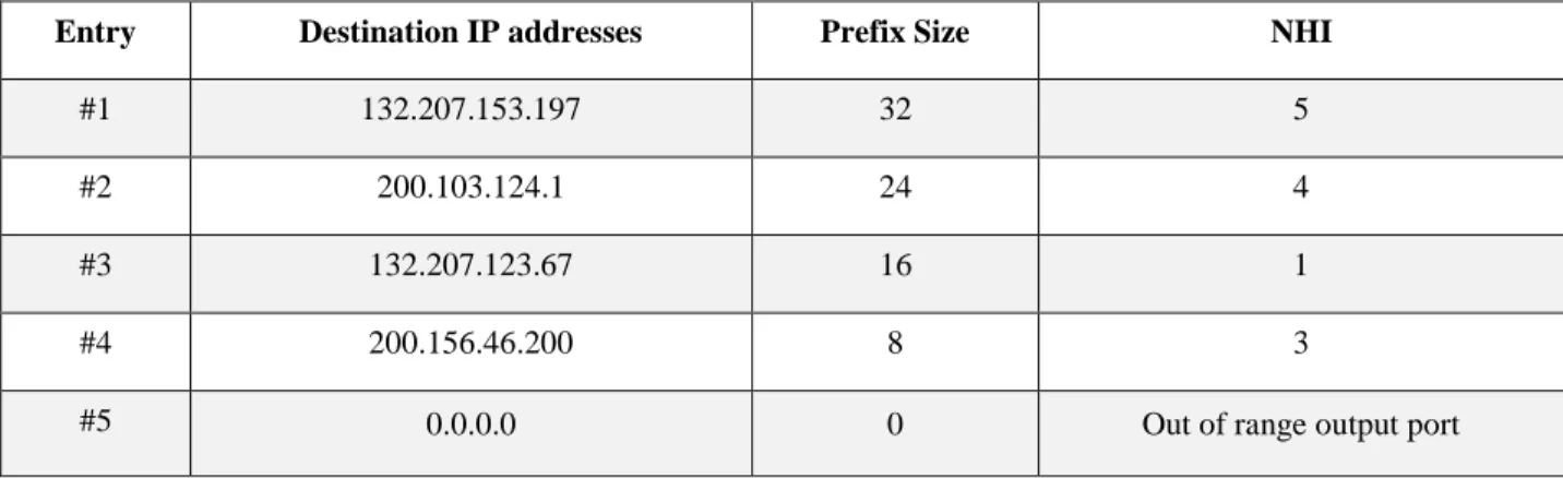
An example FIB is shown in Table 1.1, consisting of three columns. The first column contains the destination IP addresses known by the router, the second column defines the prefix size of each entry and the third column is the NHI that determines the output port number of the router corresponding to each entry. There is a special entry in every FIB that determines the default route. The default route is used when the destination IP address of the incoming packet is unknown to the router. The prefix size of the default route is equal to zero and its NHI is the default port number. Suppose an IP address lookup is performed for an incoming packet with destination IP address of 200.103.124.180 and the FIB shown in Table 1.1. Two matches are found: one match with the entry #2 with prefix size of 24 and another match with the entry #4 of the FIB with prefix size of 8. Therefore, since the prefix size of the entry #2 is larger than the entry #4, it is reported as the LPM output. Thus, the router sends the packet on port #4.
Table 1.1: A sample FIB
Entry Destination IP addresses Prefix Size NHI
#1 132.207.153.197 32 5
#2 200.103.124.1 24 4
#3 132.207.123.67 16 1
#4 200.156.46.200 8 3
#5 0.0.0.0 0 Out of range output port
1.2 Motivation
The ever-increasing speed of digital networks demands a high performance realization of LPM in network switches and routers. 5G is the fifth generation for mobile networks that meet new demands of throughput and latency for the next generation technology. Upcoming network devices, including ALEs, should be able to keep up with the performance of the 5G technology. The data rate of 5G technology is up to 10 Gbps for hundreds of active users at once [4], while its latency is in the order of the millisecond [5] [6].
To respect the constraints of the 5G technology, the performance of the ALE is evaluated using two categories. The first category concerns the IP address lookup and the second category
concerns updating the FIB. In the first category, there are two metrics for evaluating the performance of the IP address lookup: Lookup Latency (LL) and Lookup Throughput (LT). LL is the delay between the arrival of one packet to the ALE until the corresponding information of the LPM is available. LT is the number of incoming IP addresses handled in every time unit for one ALE. In the second category, there are two metrics for evaluating the performance of the FIB update: Update Latency (UL) and Update Throughput (UT). UL is the update delay, which measures the amount of time it takes from placing an update request to its actual occurrence. UT is the number of updates handled in a time unit for an ALE.
The control plane of a router can receive three types of update information: Addition (A), Modification (M) and Delete (D). For an addition, a new IP address along with its NHI and prefix size information is added to the FIB. In a modification, only the NHI corresponding to the match is revised. In a delete, the entry corresponding to that address is removed from the FIB completely. The latency and throughput can be measured for each type of update: ULA, UTA, ULM, UTM, ULD, UTD. ULA and UTA are the update latency and update throughput of the addition, respectively. ULM is the update latency of the modification while UTM corresponds to the update throughput of the modification. ULD and UTD are dedicated to the update latency of delete and update throughput of delete, respectively. Future ALEs should meet the requirements of 5G technology in terms of LL and LT, and their update mechanism should respect the constraints of ULA, UTA, ULM, UTM, ULD and UTD.
Apart from performance, another requirement for ALEs designed for 5G technology is to support the growth of the Internet of Things (IoTs). The IoT is the network and communication of the internet-enabled devices, systems, vehicles and other items that are connected to the internet. Due to the ever-increasing growth of the IoT, there will be a great demand for more IP addresses and thus larger FIBs in the routers [7]. Currently the FIB size for IPv4 addresses is near 500 k entries while for IPv6 it is around 26 k entries [8]. In the near future, the number of IPv4 addresses is expected to increase up to 2 M entries causing the depletion of IPv4 addresses [9]. This will likely cause the number of IPv6 entries to increase rapidly instead [10]. In all cases, future ALEs will have to support FIBs with a very large number of entries.
1.3 Objectives
The existing approaches for IP lookup can be categorized into three types: Content Addressable Memory (CAM)-based [11], [12], [13], and trie-based search techniques [14], [15], [16], [17] and CAM-emulation [18], [19], [20], [21]. CAM is a special type of high-speed memory that has the ability to search its entire contents in one clock cycle. CAM-based techniques suffer from high power consumption and high cost of CAMs. Trie-based techniques employ the trie data structure in their design which causes nondeterministic latency and external memory accesses. CAM-emulation techniques emulate the CAM functionality to avoid the shortcomings of CAM-based techniques.
In this thesis, we propose multiple high-performance ALE architectures that support large FIB tables. We suggest a novel architecture using CAM-emulation techniques to avoid the limitations of CAM-based and trie-based techniques. The proposed architectures for ALEs should meet the LL and LT requirements of the 5G technology and constraints of a potential next generation designs in terms of FIB sizes. Our design should support a FIB with a size of around 500 k entries for IPv4 addresses. In terms of LT, IP addresses normally arrive at a router at a rate of between 150 M to 250 M packets per second. The maximum acceptable LL is application dependent and varies between applications.
In summary, the main objectives of this thesis are:
Proposing high performance architectures for IP address lookup supporting existing large FIBs in accordance with networks constraints in terms of LT and LL.
Avoid using expensive and power hungry CAMs in the design and producing comparable results to CAM-based approaches in terms of logical resource usage and CAM cost.
The proposed architectures must eliminate the drawbacks of trie-based techniques in terms of using external memory usage and having nondeterministic latency.
Simulating and synthesizing the proposed architectures and comparing their results together and the existing work on IP address lookup.
1.4 Thesis Outline
The remainder of this thesis is organized as follows. Chapter 2 presents the existing work on IP address lookup and provides a comparison on the conventional approaches. Chapter 3 describes the proposed architectures for IP address lookup in four sections: the Full-Serial (section 3.1), the Full-Parallel (section 3.2), the IP-Split-Bucket (section 3.3), and the IP-Split-Bucket (section 3.4). Chapter 4 presents the experimental results of the proposed architectures and comparison of the most efficient proposed architecture with CAM-based, trie-based and CAM-emulation techniques. Chapter 5 concludes the thesis and highlights possible directions for future work.
CHAPTER 2
RELATED WORK
This chapter introduces the framework of the IP address lookup process in the ALE. It provides an overview of the existing work on the IP lookup categorized into three types: CAM-based, trie-based and CAM-emulation techniques. Section 2.1 presents an overall description of the ALE and its structure. The remaining sections are dedicated to describing and comparing the existing work.
2.1 Address Lookup Engine
The ALE performs the IP lookup on all entries of the FIB table. As shown in Figure 2.1, the ALE consists of three main blocks: a Match Block (MB), a Priority Encoder Block (PEB) and a NHI Block (NHIB) [12], [18]. A MB searches the FIB entries for all possible matches with the incoming IP address. Match Lines (MLs), shown in Figure 2.1, specify whether there is a match in the FIB or not. For example, in case of a match in address 𝑖, 𝑀𝐿(𝑖) would be 1 otherwise it would be 0. A PEB receives all the MLs and selects the match with the highest priority. In a LPM algorithm, the prefix size determines the priority. An NHIB contains a memory storing the output port numbers dedicated for each entry of the FIB. The NHIB uses the address of the selected match and gives the next hop number as its output.
The ALE architecture regardless of its NHIB is equivalent to a string matching engine. A string matching engine searches for all occurrences of an input string inside a predetermined set of target strings. When a match is found, the corresponding location is given as the output result.
Each string is an ordered vector of symbols of a given alphabet. Latin, Binary and DNA are examples of existing alphabets. High-performance string matching is required in several applications, particularly in real-time systems such as IP address lookup. A string matching engine with a binary alphabet and input string size of 32 (IPv4) or 64 (IPv6), can be applied for the MB and the PEB of the ALE.
Several approaches have been proposed to implement the MB and PEB in prior work. CAM-based techniques employ a CAM to perform the process of the MB and the PEB of the ALE [12]. Researchers using the trie-based techniques implement the MB using a trie data structure [14]. In CAM-emulation techniques, researchers emulate the CAM functionality to implement the MB and PEB to avoid the shortcomings of the CAM-based [22]. We review the previous approaches on the IP address lookup in the following sections. Section 2.2 describes the CAM-based existing work on IP address lookup. Section 2.3 and section 2.4 present the existing work using trie-based and CAM-emulation techniques, respectively.
2.2 CAM-Based Techniques
A CAM is a memory that acts as the opposite of a standard RAM. A RAM receives an input address and gives the data stored in the corresponding address. On the other hand, a CAM receives a data as an input and passes the address of the data item, if it is present. In a CAM search for an entry, there are three possible cases for a result:
1. If a match is found, the address of the match is the output. For some implementations, a CAM gives the incoming data along with its match address as the outputs.
2. If no match is found, a default out-of-range address is generated as the output address or a special error signal is activated.
3. If more than one match is found, the match with the highest priority is selected using a priority encoder. The priority of the contents is design dependent. For instance, in the LPM algorithm the match corresponding to the largest prefix size has the highest priority.
CAM-based techniques thus use CAMs to perform an instant search in the entire FIB. Despite the high-speed search they offer, CAM-based techniques have three drawbacks: their throughput is limited by the CAM access speed, they consume high power, and they are expensive. Aiming to mitigate these drawbacks, some researchers have proposed techniques and algorithms to
minimize the size of required CAMs. These techniques commonly combine CAMs with low-cost circuits that handle less time-critical activities. The existing work using CAM-based techniques can be classified based on the CAM type. There are two types of CAMs: Binary CAMs (BCAM) and Ternary CAMs (TCAM). Section 2.2.1 presents the TCAM-based approaches to solve the LPM problem. Section 2.2.2 reviews an approach using a hybrid architecture of TCAMs and BCAMs for IP address lookup.
2.2.1 TCAM-Based Techniques
A TCAM is a type of CAM that provides a flexible search in the memory. Bits in a TCAM have three states: 0, 1 and ternary state. The ternary state is defined with ‘X’ and is a ‘don’t care’. It provides the possibility of matching a ‘1’ and a ‘0’ at the same time. For instance, the data word ‘11X’ is a match with either ‘110’ or ‘111’. Thus, there is a possibility of finding multiple matches in a TCAM. Therefore, a TCAM requires a priority encoder in order to find the entry with the highest priority.
There are two types of priority mechanisms in a TCAM: explicit and inherent. In an explicit priority mechanism, an extra field of priority is stored in the TCAM along with its contents. Therefore, the match with the highest priority is selected based on its priority field. This mechanism is easy to update but consumes more resources since an additional priority field is added to every entry of the table. In an inherent priority mechanism, the contents are sorted based on their priority. Therefore, the match with the lowest address in a TCAM is the match with the highest priority. This mechanism is costly to update since it requires resorting all the contents of the table when a new IP address is added to the table [22].
Existing TCAM-based approaches to implement the MB and PEB of an ALE will now be presented in the order of their publication years.
Zheng et al. (2004) proposed a TCAM-based ALE with high throughput and low power consumption [11]. They applied multiple parallel partitioned TCAM chips in their architecture to achieve high throughput. They divided the FIB into 16 evenly distributed groups of IP addresses. Each group is stored inside one of the partitions of the TCAMs. A “load-balance-based” algorithm is proposed to balance the lookup traffic of the 16 groups between the partitioned
TCAMs. In Zheng et al.’s approach one partition of the TCAM is enabled at a time to minimise the power consumption. For every lookup, the incoming IP address defines the enabled partition. The architecture is shown in Figure 2.2. It consists of four sections: index logic, priority selector, lookup unit and ordering logic. Index logic starts the lookup process by determining the enabled partition using the incoming IP address. Due to the possibility of having multiple TCAMs with enabled partitions, a priority selector is required to choose the least busy TCAM to perform the lookup. Since each lookup unit contains one TCAM chip, the problem size is decreased into a partition in only one of the TCAMs. The last process is the ordering logic that puts all the NHIs of incoming IP addresses in the same order of the incoming traffic.
Figure 2.2: Architecture of multi-chip structure and chip partitioning technique [11]
For implementation results, Zheng et al. have proposed an example with 4 TCAMs of size 256 𝑘 × 36 b which contain 8 partitions. Supporting a FIB with maximum size of 819.2 k, it achieved a 133 MHz clock frequency. Maximum power consumption of the implementation was 4 watts and the maximum lookup throughput was 533 Mpps with an average processing latency of 75 ns. In 2005, Pao presented a new organization for commercial TCAMs of the SiberCAM family [23] for the purpose of IPv6 Address Lookup [12]. Available commercial TCAM chips have a fixed word length size of 36, 72, 144 or 288 bits. Therefore, for a 128-bit IPv6 address lookup technique, a commercial TCAM with word length of 144 bits is required for all prefixes
Selector #k #1 #2 . . . #k
regardless of their actual size. Pao proposed a novel two level organization that exploits the prefix length distribution of real-life FIBs. Most IPv6 prefixes are less than 64 bits long. The largest width of the available TCAMs in the 64-bit range is 72-bit TCAMs. Therefore, a 72-bit TCAM is applied for the IP addresses with prefix size of 72 or less. For prefix sizes of more than 72 bits, the IPv6 address lookup process is split into two steps handled by 72-bit TCAMs. Pao’s approach leads to efficient TCAM utilization. It improves space utilization by 50% and reduces lookup time by 30% to 45% compared to the conventional method.
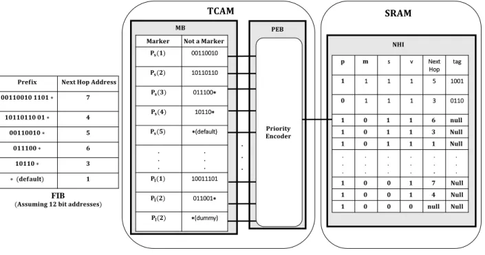
Figure 2.3 illustrates a sample FIB organized inside a TCAM and a SRAM following Pao’s approach. The MB is divided into two partitions 𝑃𝑠 and 𝑃𝑙. The 𝑃𝑠 partition contains table entries
with prefix sizes less than 72 bits (not a marker) and the first 72 bits of prefix sizes more than 72 bits (marker). The 𝑃𝑙 partition contains the entries with prefix sizes more than 72 bits (marker). When a match is found in the 𝑃𝑠, it is checked whether the match is a marker or not. If the match is not a marker the NHI of that address is valid. Otherwise, we need to calculate the address of NHI based on the marker and the remaining 56 bits of the IPv6 address.
Figure 2.3: Two-level organization in TCAM [12]
Figure 2.4 shows the architecture of the overall system. First, a network processor sends all the incoming 128-bit IPv6 addresses to the input FIFO buffer. Second, the level-selection module
00110010 10110110 011100∗ 10110∗ ∗(default) . . . . . . 10011101 011001∗ ∗(dummy) FIB . . . s v Next Hop tag 1 1 1 5 1001 1 1 1 3 0110 .
sends a 1-level command for the prefix sizes smaller than 72 and a 2-level command for prefix sizes more than 72. Moreover, it sends the search key to the TCAM for the second cycle operation. The pipelined TCAM and the SRAM are the third and fourth modules defining the NHI. The fifth module consists of two registers: B1 and B2. For a longest match with prefix sizes of more than 72-bits, five fields of the B2 register specify the second cycle operation. However, for a longest match with a prefix size less than 72 bits, the results are sent directly to the output FIFO buffers regardless of the operations in B2.
Figure 2.4: Hardware interface for TCAM co-processor [12]
2.2.2 Hybrid TCAM-BCAM Technique
A BCAM is the simplest type of CAM with the two states 0 and 1. Applications that require an exact match utilize BCAMs. It is not possible to find multiple matches simultaneously in a BCAM. Therefore, BCAMs have a simpler comparison circuit than TCAMs. They require fewer transistors and have lower power consumption than TCAMs [24]. Some of the existing works exploit the advantages of BCAMs by replacing TCAMs with BCAMs when possible.
In 2010, Sun and Kim proposed a hybrid TCAM-BCAM-based ALE that stored the fixed FIB parts in BCAMs instead of TCAMs [24]. They suggested a power efficient architecture with low area consumption compared to traditional TCAMs. Sun and Kim studied the distribution of IP address prefixes of real-world FIBs of the years 1997 to 2009. Using the characteristics of prefix distributions, they divided the FIB into seven groups (𝑃1, 𝑃2, 𝑃3, 𝑃4, 𝑃5, 𝑃6, 𝑃7 ) based on their prefix sizes. The groups 𝑃1 to 𝑃7 contain IP addresses with prefix sizes of 8, 9-15, 16, 17-23, 24,
unfixed. The fixed part contains only the binary values (where the state of ‘X’ does not exist) that are handled by BCAMs. The unfixed part contains the remainder of the IP addresses that are implemented in TCAMs. The purpose of this division is to minimise the area and power consumption of the design by replacing TCAMs by BCAMs whenever possible.
The approach presented in [24] splits the LPM process into a three-stage operation as shown in Figure 2.5. The first two stages are equivalent to the MB of the ALE. The first stage consists of parallel TCAMs and BCAMs giving the comparison results of the unfixed and fixed parts, respectively. The second stage is the parallel AND operations calculating the match results. The last stage is equivalent to the PEB that consists of two levels of priority encoders. The PEB consists of multiple levels of small priority encoders instead of one large priority encoder in order to reduce the complexity of the design.
Figure 2.5: Hybrid architecture of TCAM and BCAM [24]
By exploiting the characteristics of BCAMs and TCAMs, this hybrid architecture results in an improvement in power consumption, area usage and throughput. In terms of update, a traditional TCAM sorts a large FIB based on the prefix sizes. However, an update of Sun and Kim’s approach requires multiple small groups of IP addresses to be sorted based on their prefix sizes in parallel. Therefore, it reduces the number of clock cycles for an update process to 50% compared
Priority Encoder Priority Encoder Priority Encoder Priority Encoder
to traditional TCAMs [24]. Moreover, this parallel update leads to an increase in the throughput of IP packet processing.
2.3 Trie-Based Techniques
Static RAM (SRAM) memories are more efficient than TCAMs in terms of hardware complexity and performance. SRAMs support higher speed, more density and lower power consumption compared to TCAMs, as shown in Table 2.1. Since commercially available TCAMs have fixed word length size with bounded depth, they are less versatile to new protocols and addressing techniques compared to SRAMs. Moreover, TCAMs are more expensive than SRAMs. Some approaches [14], [15], [16], [17], [20], [25] exploit the advantages of using SRAMs instead of traditional TCAMs such as trie-based techniques.
Table 2.1: TCAM and SRAM comparison [14]
Type of Memory Maximum Clock Rate
(MHz)
Cell Size (Number of Transistors)
Power Consumption (Watts)
TCAM (18 M bits Chip) 200 16 12~15
SRAM (18 M bits Chip) 400 6 ≈ 0.19
Trie-based techniques create search trees from the FIB and store the tree information in SRAMs using a trie data structure [14], [15], [16], [17]. Trie-based techniques require traversing the search tree from the root node to leaves serially. Therefore, these techniques are inherently slower than TCAM-based ones. As the size of the FIB increases, the memory space required to store the trie information grows rapidly. For large LPM problems, trie information cannot be stored in on-chip memories. Hence, the utilization of large external memories is inevitable [15]. External memory access is the main performance bottleneck for trie-based techniques. Several approaches attempt to minimize either the number of external memory accesses for a search or their latency [16], [17]. However, accessing external memory remains the main performance-limiting factor in large trie-based designs.
In 2006, Baker and Prasanna [17] proposed an efficient string matching approach using a trie-based technique. They suggested a tool that provides automatic synthesis of highly efficient NIDS on an FPGA. This tool generates two architectures. The first architecture is a pre-decoded
shift and compare block. A high-level graph-based partitioning of strings is applied in the first architecture to reduce the size of decoders and share the shift registers. With partitioning, the goal is to maximize the similarity of patterns inside each partition. The second architecture is a tree-based prefix sharing block that is responsible for reducing the redundant comparisons. Hence, the tool they proposed improves the area consumption and performance while reducing redundant comparisons.
Hoang Le et al. (2008) exploited the advantages of SRAMs over TCAMs by implementing a SRAM-based IP-lookup architecture with a binary-tree-based design on FPGA. It supports a FIB of 228 k entries with a high throughput of 324 MLPS (multi lookup per second) while using an external SRAM to support a larger FIBs [14]. Figure 2.6 shows the global view of the proposed DUal linear Pipeline architecture for IP lookup (DuPI). The FIB is converted into a binary search tree according to their prefixes sizes. The tree information is stored inside a SRAM. Using two parallel-pipelined levels and a dual Read/Write SRAM, this architecture supports two packets at a time. The maximum number of pipelined stages is determined by two factors: the size of the tree and the maximum number of operations required to traverse the tree.
Figure 2.7 illustrates the top-level architecture of the DuPI supporting updates. It handles two types of updates: in-place update and new-route update. In-place update modifies, removes or adds every incoming IP to the binary search tree individually after the tree is constructed. A new-route update changes the binary search tree completely and requires a rebuild of the tree.
In 2011, Yang, Erdem and Prasanna proposed an FPGA-based architecture for IP lookup using trie-based technique [15]. They suggested a Combined Length-Infix Pipelined Search (CLIPS) that performs a LPM in 𝑙𝑜𝑔 (𝑙 − 𝑐) phases, supposing that 𝑙 is the size of the IP address and 𝑐 is a design constant. Each phase has an individual local infix table mapped to an FPGA using on-chip BRAMs and off-on-chip SRAMs. Using external memories, CLIPS supports very large FIBs with high throughput. According to the simulation results for a 9.5 M - entry IPv4 FIB, the CLIPS architecture supports 312 MLPS throughput while using 4 external SRAM memories with 28 Mb of BRAM on chip memory.
Figure 2.6: DuPI architecture [14]
Figure 2.7: Global DuPI architecture supporting updates [14]
In 2013, Matoušek, et al. [16] proposed a trie-based approach introducing memory efficient dedicated hardware for IP address lookup. They suggested a new representation of IP prefix set in memory applying novel types of nodes and an algorithm to map the nodes to the tree. The generated tree consumes less memory compared to existing trie-based approaches. The proposed architecture consists of several pipelined processing elements as shown in Figure 2.8. Each processing element is responsible for one step of a LPM algorithm. Using dual port memories and two levels of pipeline, the performance is improved by a factor of two.
Previous LPM flow information Previous LPM flow information Previous LPM flow information Previous LPM flow information
In 2016, Mun and Lim presented a trie-based IP address lookup using a Bloom filter [26]. To improve the efficiency, they reduced the number of false positive results of the bloom filter significantly using the characteristics for the trie-based techniques. Consequently, the number of off-chip trie accesses of non-existing nodes is reduced. They performed an IP address lookup using a reasonable amount of on-chip Bloom filter and off-chip trie accesses.
Figure 2.8: Double level of pipelined processing elements [16]
2.4 CAM-Emulation Techniques
Some researchers proposed approaches to emulate the functionality of commercially available CAMs while reducing their cost and power consumption. These approaches are known as CAM-emulation techniques [18], [19], [20], [21]. Taking advantage of FPGA configurability, implementing ALEs on FPGAs offers flexible and scalable IP address lookup process. The objective of CAM-emulation technique is to provide a fast and parallel search that addresses the main shortcomings of CAM-based approaches. It avoids the high hardware cost and high power consumption of CAMs, while providing comparable performance. In the following, some of the existing work on CAM-emulation technique are categorized into two groups based on the type of the emulated CAM: BCAM-emulation and TCAM-emulation techniques.
2.4.1 BCAM-Emulation Techniques
In a BCAM-based FIB, only one match is allowed at a time. Therefore, no priority encoder is required for a BCAM. To convert a FIB into a BCAM-based FIB, all the entries of the FIB with prefix size less than 32 bits should be expanded to 32-bit size. After the 32-bit expansion, it is possible to have multiple equivalent entries. For such a case, all entries except the one with the
Processing Element Processing Element
IPv4/IPv6 address NHI
Dual Port RAM
Dual Port RAM
Processing Element Processing Element
IPv4/IPv6 address . . . NHI
largest prefix size are removed from the FIB. As a result, the FIB is adapted to the rules of the LPM for IP address lookup. In this section, we discuss an existing approach that emulates the BCAM functionality for the LPM problem.
In 2000, Guccione et al. in [27] proposed a run-time reconfigurable high-speed implementation of BCAM on FPGA called Reconfigurable CAM (RCAM). RCAM produces a faster, smaller and more adjustable BCAM compared to traditional ones. Figure 2.9 illustrates the MB of the RCAM used for IPv4 address lookup. The incoming IPv4 address is divided into 8 groups of 4 bits. The comparison of each group is handled by one Look Up Table (LUT). There are two intermediate AND gates handling the results of every four LUT. As shown in Figure 2.9, the final match result is the output of a final AND gate applied on the results of the intermediate AND gates. In this approach, the data in the FPGA are stored in LUTs instead of Flip Flops (FFs). This leads to a reduction in the CAM’s size and an increase in its throughput [27].
The JBits tool is applied to reconfigure the BCAM and modify different parts of the FPGA at run-time, such as LUTs. Therefore, it is possible to resize dynamically the RCAM at run-time. This results in having a possibility of allocating and reallocating the BCAM resources at run-time. In [27], the authors does not present implementation results for their approach except one test case. The maximum supported table-sizes for the RCAM implementation on the Virtex V1000 FPGA are 3 k and 1 k for IPv4 and IPv6 addresses, respectively [27]. However, the size of real-world FIBs are larger as mentioned in section 1.2. For example, the Mae-West FIB [14] is 27 times larger than the supported table size.
In 2004, Clark and Schimmel proposed a BCAM-emulation approach for string matching [21]. The authors suggested an FPGA implementation of a scalable string matching design supporting network constraints. Their approach allows adjusting the trade-off between capacity and throughput according to application requirements. They applied multi-character decoders to their design in order to improve performance and eliminate redundant comparisons in string matching. The multi-character decoder shown in Figure 2.10 processes multiple input strings at once and provides all possible comparison results at once using character decoders.
Figure 2.10: String matching with multi-character decoder [21]
2.4.2 TCAM-Emulation Techniques
TCAM-emulation techniques have been proposed for many TCAM applications such as IP address lookup, to replace expensive TCAMs with low cost circuits.
In 2002, Ditmar et al. suggested a dynamically reconfigurable FPGA-based TCAM-emulation design for IP characterizations [22]. IP characterization is the procedure of classifying the packets based on the information in their header. For an IPv6 characterization, the TCAM should be 315 bits wide in order to contain all the information of the IPv6 header such as source address, destination address, incoming link, outgoing link, etc. Thus IP characterization cannot be easily supported by commercially available TCAMs, since a TCAM’s word length size is not usually
. . . . . . . . . . . . . . . . . . . . . . . .
equal to 315 bits. Ditmar et al. described a TCAM-emulation design for IPv6 characterization with the following abilities:
1. Supporting variable size TCAM search words 2. Dynamic update of the FPGA using the JBits tool
3. A hybrid explicit-inherent priority mechanism for a more efficient update
The authors propose dividing each search word into 5 pipelined stages of blocks of 64-bits and to connect the blocks to each other with shift registers. Since ternary states are not required in the comparison in a TCAM, the blocks containing the ternary states are not stored. The reduction in the size of the TCAM word is shown from ‘a’ to ‘c’ in Figure 2.11. If no block is removed in the design, a match result is given every 5 cycle. In order to respect the 5 cycles of the match, deletion of a ternary block leads to two consecutive levels of pipelined stages. Consequently, there is a possibility of storing variable-size words. Moreover, there is no waste of space in the TCAM. Consequently, it is possible to store more entries.
The general architecture of this approach is presented in Figure 2.12. The MB implemented by the structure shown in Figure 2.11, finds multiple matches with the incoming data (𝐷𝑎𝑡𝑎𝑖𝑛).
Therefore, the MB is followed by the PEB to find the match with the highest priority among all possible matches. In order to exploit the advantages of both priority mechanisms, the authors employ a hybrid explicit-inherent priority encoder. As shown in Figure 2.12, beside a typical priority encoder they have added a switch box configured by JBits tools. The switch box is responsible for routing the possible matches to the priority encoder. There are 8 possible priority values for the entries. When there are multiple matches with the same priority value, inherent priority is applied.
According to Ditmar et al., the most efficient TCAM implementation for IPv6 characterisation could fit a maximum of 256 320-bit words where an inherent/explicit priority mechanism is applied. For this case, there is a 47% utilization of the Xilinx Virtex XCV1000 FPGA while achieving a frequency of 17.2 MHz and throughput of 3.4 M searches per second.
Figure 2.12: Physical structure of dynamic reconfigurable FPGA-based CAM [22]
In 2012, Ullah et al. proposed a SRAM-based TCAM-emulation design i.e. TCAM [20]. SR-TCAM is a generic architecture, applicable to any SR-TCAM application. As shown in Figure 2.13, this architecture is specified into the MB and the PEB. The entries are stored in SRAMs instead of TCAMs in this architecture. Therefore, the conventional TCAM is divided vertically into 𝑛 groups. The groups are stored in corresponding SRAMs known as Bit Position Tables (BPTs) and Address Position Table (APT).
To perform the search, the incoming 𝑊-bit search-word is partitioned into 𝑛 sub-words of 𝑤 bits; where 𝑊 = 𝑛 × 𝑤. Each sub-word is sent to its corresponding BPT to check for its availability. Every BPT accepts 𝑤 bits as an input and contains all possible combinations of 𝑤 bits (2𝑤 bits).
For example, the 𝑖𝑡ℎ sub-word of the incoming search-word is checked inside the 𝑖𝑡ℎ BPT for its
availability. If the value of the sub-word is 𝑀, then the 𝑀𝑡ℎbit among all the 2𝑤 bits of the corresponding BPT is checked. The BPT has 1-bit output of 0 or 1. When the output value is ‘1’, a sub-word match is occurred. Otherwise, the search process is stopped.
If all BPTs have outputs with a value of ‘1’, then the Address Position Table Address Generator (APTAG) will be activated. The APTAG generates a value that corresponds to a row inside the APT. The APT contains 2𝑤 rows of 𝐾 bits. Each row is dedicated to one possible sub-word value
that contains all the 𝐾 addresses of the TCAM words. Therefore, every APT accepts an Address Position Table Address (APTA) generated by APTAG to check inside its APT. If there is a ‘1’ in the 𝑗𝑡ℎ position of the corresponding row, the value of 𝑗 indicates the location of the sub-word
inside the TCAM.
The last step is checking all the APT outputs with value of ‘1’ to find those with common positions. In other words, if all the matched sub-words are dedicated to the same address position, there is a match with the input word on that position. For that matter, a 𝐾-bit AND gate is applied to find all potential matches of the incoming search-word. Next, the output of the 𝐾-bit AND gate is sent to the PEB to find the match with the highest priority.
Ullah et al. implemented the SR-TCAM for a table size of 512×36 on a Virtex-5 xc5vlx220 FPGA. It consumes 1966 LUTs and 1975 FFs. For that design, the SR-TCAM achieves a clock period of 48.7 ns and power consumption of 2.16 mW.
Figure 2.13: Architecture of SR-TCAM [20]
In 2013, Rasmussen et al. proposed a TCAM-emulation implementation of the LPM on FPGA [18]. The implementation of the MB is equivalent to ALE. On the other hand, the PEB is
implemented by two approaches: CN-LPM and G-LPM. In the CN-LPM architecture proposed by Rasmussen et al., the PEB is implemented by a pipelined multi-level address encoder as shown in Figure 2.14. The PEB has 𝑁 − 2 inputs for a FIB of 𝑁 entries. The inputs of the PEB are identified with 𝑀𝐿𝑚. The 𝑀𝐿𝑚 indicates the match result and its prefix length of the 𝑚𝑡ℎ entry of the FIB. There are several comparator blocks in every level of the PEB. The 𝐶
𝑖,𝑗
block compares two of the 𝑀𝐿𝑚s to find the match with largest prefix. Therefore, the output of every comparator consists of: the prefix length and Least Significant Bit (LSB) of the address of the match. Consequently, at each level one bit is added to the previous match address, which provides the final address of the match with longest prefix size. The final match address is used by the NHI to find the output port number.
Figure 2.14: PEB of TCAM-emulation LPM [18]
As shown in Figure 2.15, Rasmussen et al. implemented the G-LPM architecture for local LPM process that is proposed by Gamache, et al. [28]. The MB consists of 𝑁 parallel comparator blocks (TC) containing the 𝑁 entries of the FIB. The sequential pipelined levels of the PEB are shown in Figure 2.15. They leave out all the matches except the match with the longest prefix
size in a step by step operation. For IPv6 address lookup, with prefix sizes in the range from 0 to 128, it requires 7 levels of pipelined levels. Each pipelined level is responsible for one bit of the prefixes. In the first level, the validity of all the most significant bits are checked. Only the survivors of the comparison with a validity are sent to the next level. This process continues until there is a local winner (one survivor) which is the LPM between of the 𝑁 inputs.
The FIB is divided into several sections, with each section handled by a local LPM block. As shown in Figure 2.16, all the local LPM blocks are processed in parallel to find the global LPM. Therefore, to find the global winner, all the local winners go into the same process as the local LPM, called global LPM. Finally, the address of the global winner is used to give the NHI as shown in Figure 2.16.
This architecture supports a fast incremental update of the FIB. Moreover, there is no restriction in the order of storing the entries in the FIB. To compare with traditional TCAM, a FIB of 1024 entries is implemented on the CN-LPM and G-LPM. The implementation results show an increase of 771% and 789% in the number of Adaptive LUTs (ALUT) of the CN-LPM and G-LPM, respectively.
Figure 2.15: Local LPM TCAM-emulation consists of MB and PEB [18]
×
. . .Figure 2.16: Global LPM TCAM-emulation [18]
In 2013, Jiang proposed a power efficient FPGA-based TCAM-emulation architecture [25]. Similar to Ullah et, al.’s approach [20], Jiang employed small units of SRAM-based TCAMs. Figure 2.17 shows the architecture without its update logic. All the FIB is partitioned into 𝑝 parallel RAMs. The incoming search key to the MB has the size of 𝑤 that is divided into 𝑝 small words of size 𝑤𝑖 sent to 𝑅𝐴𝑀𝑖. The size of 𝑅𝐴𝑀𝑖 is equal to 2𝑊𝑖× 𝑁. RAMi checks for a match
on a small portion (𝑤𝑖) of the input world (𝑤); where the width of the word inside 𝑖𝑡ℎ RAM
partition is equal to 𝑤𝑖. In case of a match in a partitioned RAM, there is a bit value of 1 in N-bit output in the location of the match. Afterwards, the results of all partitions are sent to an AND gate. If a match has been found on 𝑖𝑡ℎ word of the TCAM, then the 𝑖𝑡ℎ bit must remain 1 in the
final result of the AND gate. The output of the AND gate illustrates all possible matches therefore it is equivalent to the output of the MB. Subsequently, all the results are sent to the PEB to find the match with the highest priority. In this architecture, the inherent priority mechanism is applied. The output port named match has the value of 1 in case of a match and the output port named ID defines the position of the match.
. . . . . .
Figure 2.17: Underlying architecture scalable RAM-based TCAM [25]
Figure 2.18 illustrates the top level architecture of Jiang’s approach that consists of several units. Each unit is equivalent to the architecture shown in Figure 2.19. Each unit contains a 𝑈 × 𝑊 RAM-based TCAM-emulation block identical to the block shown in Figure 2.17.
Figure 2.18: Global view architecture [25]
As shown in Figure 2.19, the variable 𝑀𝑎𝑡𝑐ℎ𝑖𝑛of each unit specifies the existence of a match in
the previous units. In case of a match in the previous units, the multiplexer chooses the previous match since it has the higher priority. Otherwise, 𝐼𝐷𝑜𝑢𝑡 is chosen based on the match that is found in the existing unit. The proposed architecture in [25] presented a beneficial implementation of TCAMs on FPGA compared to the aforementioned approaches in the literature. Jiang aimed for an FPGA-based design of a TCAM with efficient power consumption while supporting large TCAM sizes. . . . . . . # . . . . . . Priority Encoder . . .
Figure 2.19: Unit architecture [25]
2.5 Comparison of the Existing Work
In this section, we present a comparison of the existing approaches in the literature. Each column of Table 2.2 shows one property of the applied technique. The first column specifies each approach by their reference number. The second column specifies the type of technique. The third one defines the applied method to implement the MB; whether it uses logical resources of FPGAs, memories, TCAM or BCAMs. The fourth column defines the type of the priority algorithm used for each technique (Inherent or Explicit). The fifth column defines whether the proposed approach supports an update mechanism to reconfigure the FPGA or not. The sixth column defines the FPGA family used in each approach. The sixth column determines the size of the tested design in each approach. The last column specifies the hardware resource usage of the FPGA implementation for each design.
Table 2.2: Comparison of existing CAM-based, trie-based and CAM-emulation techniques
Approach Technique MB PEB Update Mechanism FPGA family Table Size LUTs FFs
[27] (1990)
BCAM-emulation Cells N/A
JBit tool (Configurability at run-time) Virtex XC2V1000 3 k× 32 1 k× 64 - - [22] (2002) TCAM-emulation Cell Explicit and Inherent JBit tool (Configurability at run-time) Virtex XCV1000 256× 320 54 k 216 k [28] (2003)
TCAM-emulation N/A Explicit
Fast Incremental Update Stratix IV 1024× 64 15.8 k 11.3 k [11] (2004) TCAM-based Commercial TCAMs Commercial TCAMs N/A - - - - [21] (2004)
BCAM-emulation Cells N/A N/A
Virtex-2 8000
17,537× 32 55 k 55 k
[17] (2006)
Trie-based Cells Cells N/A Virtex-2
XCVP100 602 × 20 6 k 6 k [24] (2010) Hybrid TCAM- BCAM-based Commercial
TCAMs/BCAMs Inherent Parallel Update - - - -
[15] (2011)
Trie-based Cells, SRAM, External RAM Cells, SRAM, External RAM Incremental and Dynamical Update Virtex SX475T 9.5 M× 32 7 k 22 k [20] (2012)
TCAM-emulation SRAM Inherent N/A
Virtex
XC5VLX220 512×36 1.9 k 1.9 k
[18] (2013)
TCAM-emulation N/A Explicit
Fast Incremental
Update Stratix IV 1024× 64 15.5 k 10 k
[25] (2013)
TCAM-emulation RAM Inherent N/A
Virtex
XC7V2000T 4096×150 182 k 182 k
[16] (2013)
Trie-based Cells Cells N/A
Virtex XC6VSX475T
CHAPTER 3
PROPOSED ADDRESS LOOKUP ENGINE
ARCHITECTURES
In this Chapter, we propose and describe in detail four different ALE architectures: Full-Serial, Full-Parallel, IP-Split and IP-Split-Bucket. The advantages and drawbacks of each architecture are explained as well. Section 3.1 presents the Full-Serial architecture. Section 3.2 describes the second proposed architecture called Full-Parallel. The third architecture is the IP-Split architecture described in section 3.3. The last architecture is IP-Split-Bucket architecture that is described in section 4.4.
3.1 Full-Serial Architecture
The Full-Serial architecture is a memory-based TCAM-emulation architecture for IP address lookup. It consists of two components: a memory and a comparator. The first component is a memory that stores all the entries of the FIB sorted based on their prefix size. The second component is a single comparator that performs a serial comparison of the incoming IP address with the memory entries. The first match to occur in the serial search determines LPM output. The address of the match is determined using a counter (𝑐𝑛𝑡) that determines the position of the search and is incremented at every cycle. The first match can occur in the first cycle (first entry) or in the 𝑁𝑡ℎ cycle (𝑁𝑡ℎ entry) for a FIB of 𝑁 entries. Therefore, the search time is equal to 𝑁 2⁄
in average.
Figure 3.1 shows the Full-Serial architecture applied for an IPv4 FIB with 𝑁 entries. The memory consists of 𝑁 entries of 40 + 𝑃 bits. Each entry contains 32 bit of IPv4 address, 𝑃 bits of prefix and 8 bits of NHI. Since the egress port IDs of every router has 8 bits, the NHI is stored with 8 bits in the memory. This architecture was implemented on an FPGA using two options. In option A, the prefix size is stored using 32 bits (𝑝 = 32), while in option B it is stored with 6 bits (𝑝 = 6). The size of 𝑃 determines the format for storing the FIB entries and the comparator architecture. The following subsections describe the detailed comparator architecture of both proposed options for IPv4 ALE.
Figure 3.1: Full-Serial Architecture
3.1.1 Option A
In Option A, there is a 32-bit prefix entry with 𝑖 bits of ones followed by 32 − 𝑖 bits of zeros, where 𝑖 determines the prefix size. For instance, if the prefix size is equal to 10, the 10 MSB of the prefix are equal to one and the remaining bits are equal to zero. The architecture of the comparator for Option A is shown in Figure 3.2. The comparator performs a comparison of the 𝑐𝑛𝑡𝑡ℎ entry of the FIB and the incoming IP address using two 2-input AND, one 2-input OR and
one 32-input NOR. The first AND logic has the IP address of the 𝑐𝑛𝑡𝑡ℎ entry and its prefix as its
inputs. Another AND logic has the incoming IP address and the prefix size of the 𝑐𝑛𝑡𝑡ℎ entry as
its inputs. The results of the two latter AND operations are tested for equality by an OR and a NOR logic. In case of equality, a match is found (𝑣𝑎𝑙𝑖𝑑 = 1) and the process is terminated. Otherwise, 𝑐𝑛𝑡 is incremented and the same process is applied on the next entry of the FIB.
This architecture was implemented for different FIB sizes on various FPGAs. Section 4.1 presents the synthesis results of FPGA implementations of Full-Serial using option A.
cnt
Valid
ALE
Memory IP
(32 bits) (P bits)Prefix (8 bits)NHI
IP(0) Prefix(0) Port(0)
. . . . . . . . . IP (N-1) Prefix(N-1) (N-1)Port
Figure 3.2: Full-Serial, architecture of the comparator using option A
3.1.2 Option B
The maximum prefix size for an IPv4 addresses is 32, therefore, in option B, the prefix has 6 bits (𝑃 = 6). For instance, a prefix size of 15 is stored as “001111”. While option A requires twenty-six more bits to store the same prefix size: “11111111111111100000000000000000”.
The detailed architecture of the comparator for option B is illustrated in Figure 3.3. The comparator performs an OR operation on certain portion of the IP address of the 𝑐𝑛𝑡𝑡ℎ entry and the incoming IP address. Since the comparison is performed on the MSB of the IP addresses, the ending index of each portion is equal to the length of the IP address minus one (31). The prefix size of the 𝑐𝑛𝑡𝑡ℎentry determines the portion size of comparison at every cycle shown as 𝑖𝑛𝑡𝑒𝑔𝑒𝑟(𝑝𝑟𝑒𝑓𝑖𝑥(𝑐𝑛𝑡)) in Figure 3.3. The comparator architecture and the format of storing the FIB entries in both options shows that option B is much simpler than option A. The Full-Serial architecture is implemented using both options. Section 4.1 presents the experimental results and comparison of option A and B.
0 1
Figure 3.3: Full-Serial, architecture of the comparator using option B
3.2 Full-Parallel Architecture
Full-Parallel is the second proposed architecture for IP address lookup. It applies a parallel search on all the entries of the FIB to perform the LPM algorithm. Figure 3.4 illustrates the Full-Parallel architecture divided into three blocks: MB, PEB and NHIB. Let 𝑁 be the number of IP addresses in the IPv4 FIB. The MB consists of 𝑁 sorted parallel cells and 𝑁 parallel comparators. Every cell contains 46 bits: 32 bits of IP address, 6 bits of prefix and 8 bits of NHI. The cells are sorted based on their prefix size in descending order. Therefore, the PEB finds the match with the lowest address that determines the output of the LPM algorithm (𝐴𝑑𝑑𝑟𝑀𝑎𝑡𝑐ℎ). Next, the NHIB selects the 8-bit NHI corresponding to the 𝐴𝑑𝑑𝑟𝑀𝑎𝑡𝑐ℎ. It consists of 8 parallel multiplexers of size
𝑁: 1 with 𝐴𝑑𝑑𝑟𝑀𝑎𝑡𝑐ℎas their selector. The 𝑖𝑡ℎ multiplexer receives 𝑖𝑡ℎ bit of the 𝑁 NHIs stored in
the 𝑁 parallel cells. The output of all 𝑁 parallel multiplexers determine the 𝑁𝐻𝐼𝑀𝑎𝑡𝑐ℎ (see Figure
3.4).
The Full-Parallel architecture reduces the latency and increases the throughput of the IP address lookup by performing a parallel search on all the entries. However, it requires high resource utilization in terms of FF consumption, since all the FIB is stored in parallel cells. Section 4.2 describes the synthesis results of the FPGA implementation of the Full-Parallel architecture.
0 1
![Figure 2.1: Address lookup engine [12]](https://thumb-eu.123doks.com/thumbv2/123doknet/2347459.35246/20.918.110.823.738.962/figure-address-lookup-engine.webp)
![Figure 2.2: Architecture of multi-chip structure and chip partitioning technique [11]](https://thumb-eu.123doks.com/thumbv2/123doknet/2347459.35246/23.918.104.812.407.741/figure-architecture-multi-chip-structure-chip-partitioning-technique.webp)
![Figure 2.4: Hardware interface for TCAM co-processor [12]](https://thumb-eu.123doks.com/thumbv2/123doknet/2347459.35246/25.918.114.817.345.545/figure-hardware-interface-tcam-processor.webp)
![Figure 2.6: DuPI architecture [14]](https://thumb-eu.123doks.com/thumbv2/123doknet/2347459.35246/29.918.107.813.117.769/figure-dupi-architecture.webp)
![Figure 2.8: Double level of pipelined processing elements [16]](https://thumb-eu.123doks.com/thumbv2/123doknet/2347459.35246/30.918.240.727.279.477/figure-double-level-pipelined-processing-elements.webp)
![Figure 2.9: RCAM matching for IPv4 [27]](https://thumb-eu.123doks.com/thumbv2/123doknet/2347459.35246/31.918.181.741.755.987/figure-rcam-matching-for-ipv.webp)
![Figure 2.12: Physical structure of dynamic reconfigurable FPGA-based CAM [22]](https://thumb-eu.123doks.com/thumbv2/123doknet/2347459.35246/34.918.108.810.535.816/figure-physical-structure-dynamic-reconfigurable-fpga-based-cam.webp)
![Figure 2.15: Local LPM TCAM-emulation consists of MB and PEB [18]](https://thumb-eu.123doks.com/thumbv2/123doknet/2347459.35246/37.918.129.808.605.819/figure-local-lpm-tcam-emulation-consists-mb-peb.webp)