HAL Id: hal-01575257
https://hal.archives-ouvertes.fr/hal-01575257
Submitted on 18 Aug 2017
HAL is a multi-disciplinary open access
archive for the deposit and dissemination of sci-entific research documents, whether they are pub-lished or not. The documents may come from teaching and research institutions in France or abroad, or from public or private research centers.
L’archive ouverte pluridisciplinaire HAL, est destinée au dépôt et à la diffusion de documents scientifiques de niveau recherche, publiés ou non, émanant des établissements d’enseignement et de recherche français ou étrangers, des laboratoires publics ou privés.
Implosion tests of vacuum tubes
Alain Maupas
To cite this version:
Alain Maupas. Implosion tests of vacuum tubes. [Research Report] IFSTTAR - Institut Français des Sciences et Technologies des Transports, de l’Aménagement et des Réseaux. 2004, 39 p. �hal-01575257�
Alain MAUPAS
IMPLOSION TESTS OF VACUUM
TUBES
Report LBMC N° 0401 May 2004
Rapport LBMC n° 0401 2
g
f
e
d
c
INSTITUT NATIONAL DE RECHERCHE SUR LES TRANSPORTS ET LEUR SÉCURITÉAlain MAUPAS,
Laboratoire de Biomécanique et de Mécanique des Chocs. 25, avenue François Mitterrand, Case 24
F-69675 BRON Cedex
The author of the report thanks :
Patrick JOFFRIN, study and manufacture material of impact
Gérard GOUTELLE, tests realisation Marcel CALLEJON, tests realisation
Rapport LBMC n° 0401 3
Table of contents
Table of contents ... 3 Introduction ... 4 Tests description... 5 1. Test methodology ... 5 2. Striker ... 53. Installation of the cameras ... 6
Diagram of wiring for the triggering of the hammer, the cameras and the flash... 7
4. Position of the dummy... 8
5. Test conditions ... 8
6. Date and place of test ... 8
7. Documents supplied ... 8 Tests results ... 9 1. Test GEM 01 ... 9 2. Test GEM 02 ... 9 3. Test GEM 03 ... 9 4. Test GEM 04 ... 10 5. Test GEM 05 ... 10 6. Test GEM 06 ... 11 7. Test GEM 07 ... 11 Conclusion... 12
Rapport LBMC n° 0401 4
Introduction
MEDICAL GENERAL ELECTRIC SYSTEMS company wishes to observe the behaviour of vacuum tubes used in the lamps of radiology equipment. In certain circumstances, during manufacture, these tubes can implose. This incident can cause injuries to operators and it is necessary to study the projections of glass lamp fragments. This tests must determine the type of protection equipment needed by the manufacturer operators, such as shoes, gloves, glasses, clothing...
The LBMC, which uses high speed video cameras (1000 images per seconds and more) enabling the observation and analysis of very fast phenomena, proposes to carry out some experiments which can provide a detailed observation of these incidents.
Following a technical and financial proposal from the LBMC, the MEDICAL GENERAL ELECTRIC SYSTEMS company placed an order via the company PURCHASES SERVICE BUC under number 282436/200031602 with INRETS to carry out these experiments and to provide a test report and CD ROM containing the computer files of the recordings videos carried out.
Rapport LBMC n° 0401 5
Tests description
1. Test methodology
The tests consist of intentional breaking a vacuum tube and simultaneously recording a video sequence by means of several numerical high speed cameras. The tubes provided by MEDICAL GENERAL ELECTRIC SYSTEMS company are fixed by means of a specific assembly on a table. The test device consists of a spring-loaded jack – hold in place by a electromagnetic force – which will strike the tube. Under the impact, the tube bursts. A standing dummy is placed beside the lamp to observe the risk of contact with glass projections.
c
c
See appendix for picture of the test area2. Striker
To carry out the impact necessary to break the tube, we adapted an existing piece of equipment. It was originally conceived to release very quickly the limbs of dummies. We modified this device by adding a small hammer which is launched in fast translator movement by the release of an electromagnetic force.
armé ressort levier d'armement vis accrochage ressort ventouse électromagnétique repos tige guide tête de percuteur tige de percuteur
Rapport LBMC n° 0401 6
For the first tests, we used a pointed hammer head. However, this design did not allow a complete breakage of the lamp- see chapter dedicated to the results. For the following tests, a weighted part was installed on the end of the hammer. The drawings of the two ends used appear below. The hammer and the two ends are made of steel.
Needle end of the hammer Weighted end of the hammer
3. Installation of the cameras
Two WEINBERGER Visario cameras placed around the tube at perpendicular angles to observe the test area with the tube, the presumed zone of projection of glass and the dummy.
Lighting is provided by 6 HMI 1250 Watts projectors placed high above in each side of the experimental zone. An additional projector at ground level is placed alongside the camera, in front of the dummy.
From the second test, an additional camera was placed to observe, in very close focus, the impact on the lamp and the shattering of the tube.
For the final tests with the dummy (i.e. tests GEM 04 to GEM 07), a fourth camera was used. It was used to observe the projections of broken glass on the dummy’s head.
Camera Position Lens Aperture High
02 Side 28 mm f 2 1.31 m
08 Dummy 70 mm f 2.8 ?
66 Tube 70 mm f 2.8 1.19 m
cf Front of the dummy 35 mm f 2.8 1.38 m
For all the cameras : Image frequency = 1000 picture/s.
Shutter time between 600 et 850 micro secondes
c
Rapport LBMC n° 0401 7
Cameras are trigger by an electric control board connected to the spring-loaded jack in order to precisely synchronised the impact of the hammer with the recording sequence, taking into account the lighting available.
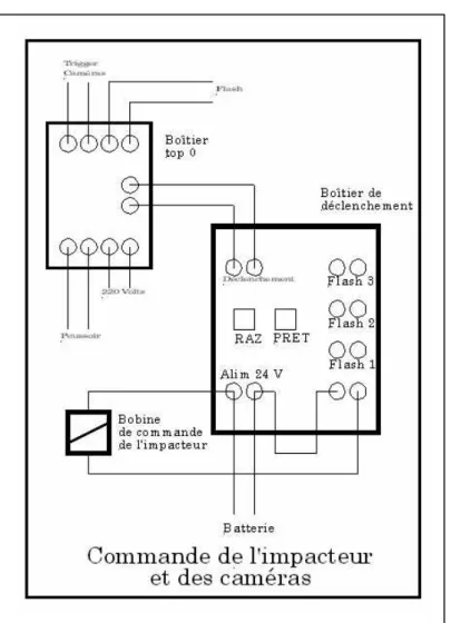
Diagram of wiring for the triggering of the hammer, the cameras and the flash
The flash is started automatically at the time of the activation of the hammer. The shock of the hammer head against glass occurs at the end of the forward movement of the hammer in a few milliseconds after. This time is about 30 milliseconds.
The video sequences last around 400 milliseconds. They can be read by means of a software such as Windows Media Player. A software such as Virtualdub, freely available on Internet, makes it possible to read the sequences picture by picture. It also enable one to apply some changes to these sequences (e;g modify the parameters of the image, capture of a single frame, cut some sequences ..°).
Rapport LBMC n° 0401 8
4. Position of the dummy
A dummy is placed upright at a distance equivalent to that occupied by the operator at the phase of tube manufacture. The dummy used is the Hybrid II equipped with a specific pelvis with a upright position. In order to hold the dummy upright, it is retained by a hoist with a hook fixed at the top of the head.
The dummy is dressed with a shirt and trousers provided by GEMS. Gloves and glasses, also provided, are placed on the hands and on the nose of the dummy.
For the last tests, the face will be covered with a fine powder of plaster to allow a better contrast of the image of the head on the high speed video cameras.
5. Test conditions
The tests proceeded in 2 phases. The first phase for the set-up of the video cameras (framing, lighting) and glass breaking device in order to determine the best procedure. The second phase – the real testing phase – in which we tested the different lamps.
6. Date and place of test
The tests took place in the laboratory LBMC of Bron.
The first phase of experiments took place between the 18 and 19 the Mars 2004.
The second phase with the dummy took place on April 6, 2004.
7. Documents supplied
The documents provided at the end of the experiments include this present tests report as well as a CD Rom containing:
• the text of the test report (pdf)
• the appendix containing the pictures (pdf)
• the jpg files of the test photos
Rapport LBMC n° 0401 9
Tests results
Seven tests were carried out. They are numbered from GEM 01 to GEM 07. The following chapter describes all the tests carried out. The photos of the equipment device and the photos of each test can be found in an appendix of this report.
1. Test GEM 01
This test is the first test of set-up. It was carried out on a faulty tube which had a crack at its top. For this reason, it was not vacuum. Struck by the small diameter hammer, the tube broke in fragments without any projections. This test was useful for verification both the installation of the cameras and lighting and whether the cameras could capture the shattering fragments of glass on the high speed video sequences.
For a better observation of the tube behaviour, we decided to add a third camera to focus on the tube and the hammer.
2. Test GEM 02
This tube was in good condition. The impact produced by the small diameter hammer did not cause a complete breakage of this tube. Indeed, the hammer with a 4 mm diameter, pierced the glass which cracked around the point of impact. So, there were no projections.
After phone contact with Mr. Ponce, it was decided to continue the tests, to equip the head of the hammer with a weight in order to create a shock ever a more significant area.
3. Test GEM 03
It is the last test of set-up. It was carried out with a standard tube and a hammer equipped with the weighed end. We observes a good implosion of the tube under the impact. The lamp was entirely destroyed. The fragments were projected all around the experimental zone. Most parts of glass were collected at a
Rapport LBMC n° 0401 10
distance of approximately 4 meters from the initial position of the lamp. The 3 video sequences carried out make it possible to observe the impact on glass, the behaviour of the tube with an internal compression before its final explosion with projections of glass fragments.
Following these tests, and after the observation of the video sequences by Mr. Ponce, it was decided to start the real tests.
4. Test GEM 04
For this first real test, the dummy was installed upright behind the table support. With a fourth camera we could observe the dummy’s head.
The hammer is positioned in such a way so that the hammer would penetrate the tube by 13 mm.
The lower part of the tube broke. The upper part of the tube is heavy (internal equipment) and then the projections in vertical way were limited. The upper part of the lamp rocked on the side and fell down on the ground. We observe some small glass fragments moving in the zone close to the dummy’s head.
5. Test GEM 05
This test was the most spectacular of the four tests carried out with the dummy in work position. Following the implosion, the glass fragments of the tube were projected all around the working area. In vertical way, these fragments moved higher than the dummy’s head. The glass fragments were projected on the ground in a circle of approximately 4.50 m diameter around the initial position of the tube. The largest fragments have a dimension of several centimetres. Thus, they present important risks of injuries. Pieces of very small size are also found on the sleeves of the shirt worn by the mannequin.
The analysis of the video images provides some temporal elements of this test :
Time in millisecondes Observations
0 Beginning of the sequence
10 Light on – Release of the hammer
23 Beginning of hammer moving
38 Contact between the hammer and the tube
Rapport LBMC n° 0401 11
53 Beginning of projection upwards
97 Arrival of the first small parts of glass near
the head
198 The large parts of glass are near the head
419 End of the sequence
6. Test GEM 06
This test is rather similar with test GEM 04. Indeed, the implosion caused the breakage of the lower part of the tube, but the upper part prevents the projection in vertical way of the large parts of glass. Only some small elements reached the head of the dummy. Some parts of glass were founded on the ground at a maximum distance of approximately 1.5 meters from the initial position.
7. Test GEM 07
The tube tested is different from the other models. It appeared as 2 parallel tubes of smaller dimensions than the tubes tested previously. Its reference is GS512-4 8764 TX4.
The impact caused the break of the first tube but the fragments remained in a zone of a few centimetres around the initial position. The main part of the lamp was not destroyed.
Rapport LBMC n° 0401 12
Conclusion
The procedure defined by INRETS and the installation at the request of the MEDICAL ELECTRIC SYSTEMS company made it possible to carry out all of the required tests.
The high speed video sequences allows to observe the tubes behaviour just at the moment of their breakage.
The very different behaviour of the various tubes could not be analysed because we did not have the precise characteristics of these tubes.
Concerning the analysis of the risk occurred by the operators at the moment of the accidental implosion of these tubes, it seems to us that two observations can be made :
Observation n°1 : The risk of occurred injuries to the operator seems
important because many elements of glass with consequent size (a few centimetres) were projected at high speed near to the operator.
Observation n°2 : The risk of serious injuries seems excluded, because it is
limited to cuts of the operator’s skin. Thus, it seems important that the operators wear some means of individual protection. The port of the glasses and the gloves must be an obligation. Concerning the prevention of cuts to the face, the wearing of mask, if it is not too incompatible with the working conditions, can bring a safety. It seems important to envisage, near the working place, to place at the disposal some means of care for the evoked injuries.
These tests allows to approach the analysis the behaviour to the shock of fragile devices. The precise definition of the means of protection for the operators could be concluded starting from these elements accompanied by an analysis of the working place and the handling required by the operator.
Appendix : Test Pictures
Listing of documents :
Picture n° 1 : General sight of experimentations ...3
Picture n° 2 : Lamp fixing...3
Picture n° 3 : Impactor with needle end...4
Picture n° 4 : Impactor with needle end...4
Picture n° 5 : Speed cam video ...5
Picture n° 6 : Synchronised lamp ...5
Picture n° 7 : Impactor with lesting end ...6
Picture n° 8 : Impactor with lesting end ...6
Picture n° 9 : Test GEM 01 - Initial position...7
Picture n° 10 : Test GEM 01 - Lamp broken after the test...7
Picture n° 11 : Test GEM 02 - Initial position before the test...8
Picture n° 12 : Test GEM 02 - Initial position before the test...8
Picture n° 13 : Test GEM 02 - Impact ...9
Picture n° 14 : Test GEM 02 - Test result ...9
Picture n° 15 : Test GEM 03 - Initial position before the test...10
Picture n° 16 : Test GEM 03 - Impact ...10
Picture n° 17 : Test GEM 03 - Implosion...11
Picture n° 18 : Test GEM 03 - Implosion...11
Picture n° 19 : Test GEM 04 - General sight of experimentations ...12
Picture n° 20 : Test GEM 04 - Dummy in standing position...12
Picture n° 21 : Test GEM 04 - Frontal sight of the experimentation...13
Picture n° 22 : Test GEM 04 - Lamp ...13
Picture n° 23 : Test GEM 04 - Lateral sight of the experimentation ...14
Picture n° 24 : Test GEM 04 - Implosion...14
Picture n° 25 : Test GEM 05 - General sight of the experimentation...15
Picture n° 26 : Test GEM 05 - Initial position...15
Picture n° 27 : Test GEM 05 - Implosion...16
Picture n° 28 : Test GEM 05 - Implosion...16
Picture n° 29 : Test GEM 05 - Implosion...17
Picture n° 30 : Test GEM 05 - Implosion...17
Picture n° 31 : Test GEM 05 - Position after the test...18
Picture n° 32 : Test GEM 05 - Position after the test...18
Picture n° 33 : Test GEM 05 - Position after the test...19
Picture n° 34 : Test GEM 05 - Element of broken glass...19
Picture n° 35 : Test GEM 05 - Element of glass on shirt ...20
Picture n° 36 : Test GEM 05 - Element of glass on shirt ...20
Picture n° 37 : Test GEM 06 - Painting of the head dummy ...21
Picture n° 38 : Test GEM 06 - General sight of the experimentation...21
Picture n° 39 : Test GEM 06 - Implosion...22
Picture n° 40 : Test GEM 06 - Implosion...22
Picture n° 41 : Test GEM 06 - After test lateral sight ...23
Picture n° 42 : Test GEM 06 - Test result ...23
Picture n° 43 : Test GEM 07 - Lamp in initial position...24
Picture n° 44 : Test GEM 07 - Lamp in initial position...24
Picture n° 45 : Test GEM 07 - After test general sight ...25
Picture n° 46 : Test GEM 07 - Implosion...25
Picture n° 47 : Test GEM 07 - Implosion...26
Picture n° 48 : Test GEM 07 - Lamp broken after the test...26
Picture n° 49 : Test GEM 07 - Lamp broken after the test...27
Appendix : Test Pictures A 3
Picture n° 1 : General sight of experimentations
Appendix : Test Pictures A 4
Picture n° 3 : Impactor with needle end
Appendix : Test Pictures A 5
Picture n° 5 : Speed cam video
Appendix : Test Pictures A 6
Picture n° 7 : Impactor with lesting end
Appendix : Test Pictures A 7
Picture n° 9 : Test GEM 01 - Initial position
Appendix : Test Pictures A 8
Picture n° 11 : Test GEM 02 - Initial position before the test
Appendix : Test Pictures A 9
Picture n° 13 : Test GEM 02 - Impact
Appendix : Test Pictures A 10
Picture n° 15 : Test GEM 03 - Initial position before the test
Appendix : Test Pictures A 11
Picture n° 17 : Test GEM 03 - Implosion
Appendix : Test Pictures A 12
Picture n° 19 : Test GEM 04 - General sight of experimentations
Appendix : Test Pictures A 13
Picture n° 21 : Test GEM 04 - Frontal sight of the experimentation
Appendix : Test Pictures A 14
Picture n° 23 : Test GEM 04 - Lateral sight of the experimentation
Appendix : Test Pictures A 15
Picture n° 25 : Test GEM 05 - General sight of the experimentation
Appendix : Test Pictures A 16
Picture n° 27 : Test GEM 05 - Implosion
Appendix : Test Pictures A 17
Picture n° 29 : Test GEM 05 - Implosion
Appendix : Test Pictures A 18
Picture n° 31 : Test GEM 05 - Position after the test
Appendix : Test Pictures A 19
Picture n° 33 : Test GEM 05 - Position after the test
Appendix : Test Pictures A 20
Picture n° 35 : Test GEM 05 - Element of glass on shirt
Appendix : Test Pictures A 21
Picture n° 37 : Test GEM 06 - Painting of the head dummy
Appendix : Test Pictures A 22
Picture n° 39 : Test GEM 06 - Implosion
Appendix : Test Pictures A 23
Picture n° 41 : Test GEM 06 - After test lateral sight
Appendix : Test Pictures A 24
Picture n° 43 : Test GEM 07 - Lamp in initial position
Appendix : Test Pictures A 25
Picture n° 45 : Test GEM 07 - After test general sight
Appendix : Test Pictures A 26
Picture n° 47 : Test GEM 07 - Implosion
Appendix : Test Pictures A 27
Picture n° 49 : Test GEM 07 - Lamp broken after the test