Open Archive TOULOUSE Archive Ouverte (OATAO)
OATAO is an open access repository that collects the work of Toulouse researchers and
makes it freely available over the web where possible.
This is an author-deposited version published in :
http://oatao.univ-toulouse.fr/
Eprints ID : 18547
To link to this article : DOI:10.1016/j.diii.2016.07.003
URL :
https://doi.org/10.1016/j.diii.2016.07.003
To cite this version : Faruch-Bilfeld, Marie and Lapegue, Franck and
Chiavassa, Hélène and Sans, Nicolas Imaging of meniscus and
ligament injuries of the knee. (2016) Diagnostic and Interventional
Imaging, vol. 97 (n° 7-8). pp. 749-765. ISSN 2211-5684
Any correspondence concerning this service should be sent to the repository
administrator:
[email protected]
Imaging
of meniscus and ligament injuries
of
the knee
M. Faruch-Bilfeld , F. Lapegue , H. Chiavassa , N. Sans
∗Imaging Department, Toulouse-Purpan University Hospital, Pierre-Paul-Riquet Building, place du Dr-Baylac, TSA 40031, 31059 Toulouse cedex 9, France
KEYWORDS MRI; Knee; Central pivot; Meniscus; Collateral ligaments
Abstract Magnetic resonance imaging has now an indisputable role for the diagnosis of
menis-cus and ligament injuries of the knee. Some technical advances have improved the diagnostic capabilities of magnetic resonance imaging so that diagnoses, which may change the therapeu-tic approach, such as a partial tear of the anterior cruciate ligament or confirmation of unstable meniscal injuries, are now made easier. This article describes the essential about magnetic res-onance imaging technique and pathological results for the menisci, collateral ligaments and damage to the central pivot of the cruciate knee ligaments.
Magnetic resonance imaging (MRI) has now an indisputable role for the diagnosis of meniscus and ligament injuries of the knee. Some technical advances have improved the diagnostic capabilities of MRI so that diagnoses, which may change the therapeu-tic approach, such as a partial tear of the anterior cruciate ligament or confirmation of unstable meniscal injuries, are now made easier.
This article describes the essential about MRI technique and pathological results for the menisci, collateral ligaments and damage to the central pivot of the cruciate knee ligaments.
MRI technique
As a general rule, MRI examination of the knee includes T1-weighted or PD (proton density)-weighted sequences in the sagittal plane without fat saturation followed by PD images with
∗Corresponding author.
fat saturation in the 3 spatial planes. Although there is no definitive consensus on the type of images in daily practice, spin echo images with a short TE and particularly PD images are the most widely used. Section thicknesses should not exceed 4 mm and the field of view should be no more than 160 mm. In recent years, there has been a growing interest in single three-dimensional (3D) isotropic, millimeter voxel images, allowing high quality multiplanar reconstructions to be obtained.
Meniscus injury
Epidemiology and clinical details
Meniscus injury is one of the most common causes of consul-tations for knee disorders. Of these, sports injuries are the leading cause with an incidence of meniscal damage in adults of approximately 9/1000 in men and 4.2/1000 in women [1]. Traumatic fissures, which occur in a healthy meniscus and in young people, are the most common lesions (68 to 75%), which can be distinguished from microtraumatic fissures in a degenerative meniscus, which is constantly increasing in incidence in ‘‘mature’’ older sportsmen and women[2,3].
Meniscal lesions cause various symptoms; the most com-mon ones are pain, locking, instability or an impression of internal disorganization[4]. Some meniscal lesions however remain entirely asymptomatic and the treatment of a menis-cal injury is currently dominated by the concept of menismenis-cal sparing in order to preserve the future of the joint cartilage.
Functional anatomy
The menisci are semilunar fibro-cartilages, which are trian-gular on section and are interpositioned between the tibial condyles and plateaux, considerably improving femoro-tibial joint congruence and playing a fundamental role in the kinetics of the knee[5,6].
The medial meniscus takes the form of an open ‘‘C’’ formed by an anterior horn, a middle segment and a pos-terior horn. The pospos-terior horn is usually thicker than the anterior one. The lateral meniscus is an ‘‘O’’ shaped struc-ture with a relatively constant thickness on section.
The different meniscal horns are fixed by meniscal frae-niae onto the pre- and retrospinal surfaces[7]. The middle segments are also fixed by ligaments (menisco-femoral, menisco-tibial and menisco-patellar). The posterior horn of the lateral meniscus is fixed to the medial femoral condyle by the menisco-femoral ligaments of Humphrey and Wris-berg and the anterior horns of the medial and lateral meniscus meet anteriorly in the transverse intermeniscal ligament.
The vascularization of the menisci is vestigial and con-sists of a perimeniscal capillary network supplied by the lateral and medial geniculate arteries[8]. The peripheral area, which only represents 10 to 30% of the sectional sur-face area of the meniscus, is vascularized from the radial arteries and is known as the ‘‘red area’’[9]. The rest of the peripheral area and the central area are avascular and rep-resent the ‘‘white’’ area. The peripheral meniscal lesions, which occur in the red area, are therefore likely to heal
whereas central meniscal areas occurring on the white area usually require meniscectomy[5].
Normal and variant MRI appearances
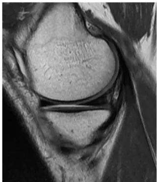
On sagittal and frontal images, the normal meniscus takes the shape of a triangle at hypointense signal. On the most lateral sagittal images, the meniscus is a ‘‘bow tie knot’’ like structure made up of the sagittal section of the middle segment combining the anterior and posterior horns (Fig. 1). It is useful to know certain anatomical variants as they can mimic meniscal fissures:
• on sagittal sections, the transition between the transverse ligament and the anterior;
• the popliteal tendon sheath;
• the menisco-femoral ligaments of Humphrey and Wrisberg which unite the posterior horn of the lateral meniscus to the medial femoral condyle;
• the oblique menisco-meniscal ligament which occasion-ally connects the anterior horn of a meniscus to the posterior horn of the opposite meniscus and may mimic a migrated meniscal fissure or a bucket handle[10]; • the discoid meniscus which is a rare congenital
malfor-mation of the meniscus. This meniscal dysplasia almost exclusively affects the lateral meniscus. Its ‘‘academic’’ diagnosis on MRI is based on seeing continuity of the ante-rior and posteante-rior horns on sagittal images[11]in at least 3 contiguous 5 mm thick sections (Fig. 2). These findings are adjusted depending on the section settings used.
Figure 1. Normal MRI appearance of the medial meniscus. Pro-ton density-weighted sagittal section: the anterior and posterior meniscal horns appear as a homogeneous, hypointense triangle. The meniscus is bow tie shaped and constructed by the section of the median segment at the center connecting the anterior horn in front of the posterior horn behind it.
Figure 2. Discoid lateral meniscus. Sagittal T1-weighted images. Continuity of the anterior and posterior horns over 3 contiguous 5 mm fixed sections. Note the myxoid degeneration of the anterior horn in this discoid meniscus.
Pathological imaging of the menisci
It is usual practice to basically distinguish traumatic menis-cal fissures from degenerative menismenis-cal fissures. Traumatic lesions are due to the application of excessive mechani-cal forces onto a healthy meniscus[12]. In young people, the fissure usually occurs from an indirect valgus injury with external rotation of the tibia with the knee flexed at 20◦ or after hyperflexion followed by sudden elevation. Conversely, degenerative lesions occur as a result of nor-mal mechanical forces applied to a meniscus damaged by interstitial myxoid degeneration[2]. Horizontal meniscal fis-sures may develop spontaneously or may be caused by minor injury.
Classification
Depending on the direction of the cleavage plane, fissures can be classified as horizontal, vertical or complex[5].
Horizontal fissures have a cleavage plane parallel to the tibial plateau and separate the meniscus into a superior frag-ment and an inferior fragfrag-ment. These horizontal lesions are ubiquitous in distinguishingly affecting the medial or lateral meniscus and are deemed to be stable although fragments, which have migrated into recesses, have been described fol-lowing damage to the middle sector of the medial meniscus
[13,14].
Vertical fissures are perpendicular to the tibial plane and follow the circumferences of the meniscus. These more commonly affect the medial meniscus. Complete injuries are considered to be unstable and divide the meniscus into a medial segment and a lateral segment. The fis-sured medical segment may migrate into the intercondylar notch and produce the classic ‘‘bucket handle’’ appearance
[15,16].
Radial fissures are perpendicular to the periphery of the meniscus and usually affect the free edge of the meniscus. Oblique (‘‘parrot-beak’’) fissures are mixed verti-cal lesions involving a longitudinal component and a radial component extending circularly in the free edge[6].
Finally, there are complex meniscal lesions which do not have any defined description and which involve several hor-izontal and vertical fissures.
MRI appearance of meniscal injuries
Meniscal fissures
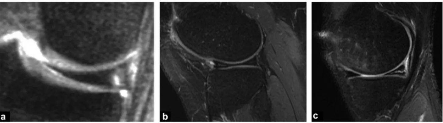
Stoller et al. proposed to classify meniscal fissures into 3 grades (Fig. 3)[17]:
• grade 1: hyperintense nodular meniscus with preservation of the meniscal surfaces;
• grade 2: hyperintense linear meniscus with preservation of the meniscal surfaces;
• grade 3: hyperintense extending to one of the joint sur-faces of the meniscus.
Whilst the distinction between grades 2 and 3 is fun-damental as it distinguishes a degenerative intrameniscal hyperintensity (Fig. 4) from a true fissure. This distinction between a degenerative meniscus and a fissured meniscus is not always very straightforward and there are many sources of error due to additional or missing appearances[6].
MRI offers excellent performance with sensitivity and specificity between 90% and 95% [18]. On MRI, meniscal fissures present as an intermediary linear hypointensity extending to one of the joint surfaces of the meniscus (Stoller grade 3), or as purely morphological abnormalities
[6].
Some semiological difficulties exist particularly a high risk of false positive findings when the fissure is only visible on a single section[3]. It is recommended that a linear intra-meniscal hyperintensity be considered to be pathological if it obviously affects the meniscal surface, i.e. on at least two contiguous sections. This concept should be adapted depending on the image acquisition technique used (3 to 4 mm sections or obtaining a 3D volume with isotropic mil-limeter sections).
In view of their orientation, radial meniscal fissures are occasionally more difficult to diagnose [19]. These result mostly in morphological abnormalities:
• interruption or amputation of the free edge on frontal images;
• discontinuity or truncated appearance of the meniscal bow tie on sagittal images (Fig. 5);
• absent or ‘‘ghost’’ meniscus with a complete radial fis-sure.
Meniscal ruptures with a bucket handle complicate approximately 10% of vertebral fissures with longitudinal
Figure 3. Stoller grades. a: grade 1: one or more intermediary nodular hyperintense sites respecting the joint surfaces of the meniscus; b: grade 2: linear intermediary hyperintensity respecting the joint surfaces of the meniscus; c: grade 3: linear intermediary hyperintensity extending to one of the joint surfaces of the meniscus.
extension[14,15]. In this case, MRI offers a sensitivity of around 70% depending on the diagnostic criteria used.
The most constant finding is the direct visualization of the migrated fragment in the intercondylar area: the ‘‘double posterior cruciate ligament (PCL)’’ sign is pathognomonic and present when the medial meniscus is damaged and the anterior cruciate ligament is intact [16]. The dislocated fragment appears as an arch-shaped hypointense band par-allel to the normal posterior cruciate ligament, producing a ‘‘double PCL’’ appearance (Fig. 6). An excessively large anterior horn a ‘‘megahorn’’ (over 6 mm in size) may also
Figure 4. Degenerative appearance of the meniscus. Sagittal pro-ton density view with fat saturation. A hyperintense area without any true-fissured linear image is seen.
Figure 5. Radial fissure of the anterior segment of the medial meniscus in a sagittal proton density-weighted view. Medial menis-cus amputating the normal appearance of the bow tie (arrow).
reflect the presence of a bucket handle (Fig. 7). In this case, the dislocated meniscal fragment adheres to the healthy anterior horn.
Other MRI signs have been validated such as the absent bow tie knot, the flipped meniscus sign or directly visualizing the meniscal fragment displaced into the intercondylar area on millimeter frontal images (Fig. 8) or axial images.
Another formal sign of meniscal instability is identifica-tion of peripheral displacement of the meniscal fragment into the femoro-meniscal recess or femoro-tibial recess
[13,14]. These displacements almost exclusively involve the medical meniscus and are a complication in 10% of cases of some horizontal fissures. Coronal and transverse sections are the best to identify these fragments[14].
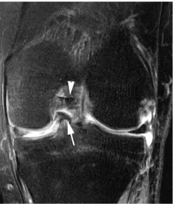
Figure 6. Bucket handle appearance of the medial meniscus with ‘‘double PCL’’ sign. Sagittal PD-weighted view with fat suppression: the dislocated meniscal fragment (arrow) is located beneath the normal PCL (arrowhead) and forms a pathognomonic ‘‘double PCL’’ appearance.
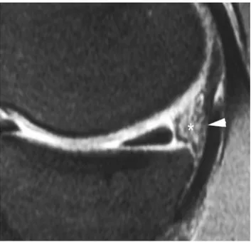
Figure 7. Appearances of anterior megahorn. Sagittal proton density-weighted view. The dislocated fragment anterior (arrow-head) attaches to the anterior meniscal horn (arrow). Note that the posterior horn is not visualized (*).
Meniscal contusions
Meniscal contusions usually occur as a result of a flexion injury with compression of the posterior horn of the medial meniscus between the condyle and the tibia (Fig. 9). MRI shows a diffuse intrameniscal hyperintensity, which may mimic a fissure[20]. The presence of a concomitant sub-chondral bone contusion generally distinguishes meniscal contusions from true fissures.
Figure 8. Dislocated bucket handle in the notch. Frontal PD-weighted view after fat suppression. The dislocated meniscal fragment (arrow) is located in contact with the ACL (arrowhead).
Figure 9. Meniscal contusion. Frontal proton density-weighted view after fat suppression. The meniscal contusion is seen as an overall hyperintense appearance of the meniscus. Note also a sub-chondral contusion of the tibial plateau and an intra-articular effusion.
Meniscal detachments
Meniscal detachments occur as a result of a violent valgus injury and are due to rupture of the capsular attachments of the meniscus. These tend mostly to affect the posterior horn of the medial meniscus adherent to the joint capsule through a capsule thickening (posterior oblique ligament).
They result in a 5 mm superior meniscal shift from the posterior edge of the tibial plate on sagittal images (Fig. 10) or liquid interpositioned between the base of the meniscus and the plane of the capsule.
The floating meniscus
This also occurs as the result of a violent injury and is due to rupture of the menisco-tibial ligament and detachment of the medial segment of the meniscus. On MRI, the detached meniscus is completely surrounded by fluid and appears to ‘‘float’’ on the tibial plateau (Fig. 11)[21].
The post-surgical meniscus
Recurrent post-meniscectomy pain raises a number of diag-nostic difficulties: repeated fissure, post-meniscectomy, chondrolysis, subchondral necrosis or algodystrophy. MRI often fails to detect recurrent fissures as meniscal resection leaves an intermediary hyperintensity ‘‘falsely’’ communi-cating with the meniscal surface[22,23]. The only finding to be recognized as pathological and interpreted as a recurrent fissure is a liquid intrameniscal hyperintensity on T2-weighted images. These limitations of simple MRI alone
Figure 10. Detachment of the posterior horn of the meniscus. Sagittal proton density view. The detached meniscus is displaced forwards. A large hyperintense (*) area is present between the base
of the meniscus and the posterior capsule (arrowhead).
Figure 11. Floating meniscus. Frontal proton density view with fat saturation. The detached meniscus is surrounded by fluid partic-ularly between its inferior surface and the tibial plateau (arrows).
have driven some authors to propose using MRI arthroscopy although here again the results are inconsistent[24—26].
Pathology of the central pivot and
collateral ligaments
Anatomy of the ligament structures of the
knee
The anterior cruciate ligament
The anterior cruciate ligament (ACL) is the ligament, which stabilizes the knee in the antero-posterior plane. It stretches
from the posterior part of the medial aspect of the lateral condyle to the prespinal surface of the tibial plateau and in extension lies parallel to the intercondylar line. The ACL is bifascicular: the antero-medial (AM) bundle is held in flexion and its role is to stabilize the knee in antero-posterior trans-lation. This is the bundle which when ruptured cause the anterior drawer on clinical examination. The postero-lateral (PL) bundle becomes stretched in near complete extension. It has a stabilization role with rotatory forces. Rupture is more likely to produce a positive pivot tests and a positive Lachman test[27,28].
The posterior cruciate ligament
The posterior cruciate ligament (PCL) is thicker and extends from the anterior aspect of the lateral surface of the medial femoral condyle to the retrospinal surface. It is both extra-capsular and extra-synovial and is orientated strictly along a sagittal plane. It is occasionally accompanied in its path by the menisco-femoral ligaments of Wrisberg and Humphrey, which may give it a focal nodular or doubled appearance on sagittal images.
The medial collateral ligament
The medial collateral ligament (MCL) is wide and flat and is formed from two, superficial and deep planes, separated by an intermediary layer made up of adipose tissue and a serous bursa. The superficial plane inserts into the medial femoral epicondyle and adheres to the superficial part of the medial meniscus and the joint capsule. The deep plane is made up of a menisco-tibial ligament and a femoro-meniscal ligament and adheres closely to the capsule. The bursa and anterior tendon of the semimembranosus muscle pass between these two bundles.
The lateral collateral ligament
The lateral collateral ligament (LCL) forms an oblique thick band inferiorly and anteriorly holding the tuberosity of the lateral condyle onto the head of the fibula. The LCL has a fibular insertion, which is common with the femoral biceps tendon and does not adhere to the joint capsule because of interposition of the popliteal muscle tendon.
The postero-lateral angle point
The postero-lateral angle point consists of multiple anatom-ical structures[29], which are interconnected to a greater or lesser extent, and plays a fundamental role in the stability. It comprises the lateral head of the gastrocnemius muscle, the poster-lateral part of the anterior capsule, the posterior horn of the lateral meniscus, the popliteal muscle and ten-don (intra-articular but extra-synovial), the popliteo-fibular ligaments arcuate and fabellofibular ligaments, which are not constant findings and the iliotibial tract. Further away, the collateral fibular ligament (lateral collateral ligament) and tendon of the femoral biceps also form part of the structures contributing to the postero-lateral stability of the knee.
Normal MRI imaging of knee ligament
structures
The anterior cruciate ligament
On MRI, the ACL often appears tortuous and is frequently visible on only one or two strict sagittal sections (Fig. 12). Fibers from the two antero-medial and postero-lateral bun-dles are better seen on coronal sections and in particular on fine axial sections perpendicular to the axis of the ACL. The overall signal is intermediate and striated and is due to the orientation of the different fiber contingents, which roll around each other in a spiral and may raise diagnostic difficulties in cases of partial rupture. In this situation, the continuity of the two bundles should be examined on coronal and transverse views, where in theory they can be clearly distinguished (Fig. 13).
The posterior cruciate ligament
The posterior cruciate ligament is thick and directed along a strict sagittal plane. Its MRI appearances are of a homoge-neous hypointensity regardless of the image sequence used (Fig. 14). In the area where it crosses the menisco-femoral ligaments of Wrisberg and Humphrey, it takes on a local-ized nodular appearance and occasionally displays a local hyperintensity due to a magic angle artefact.
The lateral ligaments
These are hypointense on all images. The different layers of the tibial collateral ligament are segmented by hyperin-tense bands representing the synovial and fatty interfaces (Fig. 15).
Figure 12. Anterior cruciate ligament: normal proton density sagittal MRI view: relatively tortuous appearance of a ligament and no intra-articular effusion.
Figure 13. Anterior cruciate ligament: normal appearance. MRI: proton density frontal view with fat saturation. The two ligament sheets are seen (arrows).
Pathological MRI appearances of knee
ligament structures
The anterior cruciate ligament
Acute rupture
According to professional guidelines, MRI investigation of the anterior cruciate ligament is reserved for equivocal
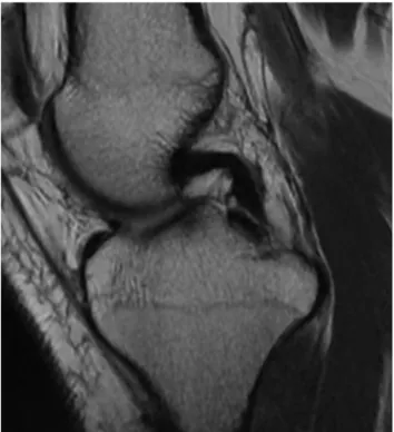
Figure 14. Posterior cruciate ligament: normal appearance. MRI: proton density-weighted sagittal view. The PCL appears hypointense and homogeneous.
Figure 15. Medial collateral ligament: normal appearance. a: MRI: proton density-weighted frontal view with fat saturation: the collateral ligament is regular, thin and hypointense (arrows); b: depending on the section, a hyperintense band is seen which represents the fatty interface between the two ligament layers (arrow).
diagnoses or inconsistencies with the clinical examination, which may be difficult in the acute stage because of a hemarthrosis and muscle contracture. MRI can also be used to investigate for the frequently concomitant bone or menis-cal injuries.
The rupture may be diffuse or local and is usually at the point of the proximal insertion, occasionally it occurs in the main body. Continuity between the two bundles of ACL fibers should be examined particularly in a coronal plane or per-pendicular axial plane to confirm integrity of the ligament and identify any partial ruptures present[30]. In the acute stage, a local hyperintensity due to edema and hematoma, which is modest on T1-weighted and PD-weighted images and more intense on T2-weighted images is seen (Fig. 16).
This hyperintensity should not be confused with two dif-ferent entities: an effusion in contact with the ligament appearing as a marked hyperintensity on T2-weighed images and mucoid degeneration[31,32]in which the tendon cir-cumference is increased but tendon fibers are poorly defined and appears as a hyperintensity on both T1- and T2-weighted images.
Rarely, a ruptured ACL may become incarcerated ante-rior to the intercondylar notch then causing a flexion knee deformity and the appearance of a nodular mass interposi-tioned between the lateral femoral condyle or the tibia or a tongue with a free edge in front of the notch on MRI (Fig. 17)
[33]. MRI has a diagnostic accuracy of 90% in this situation
[34].
Figure 16. Complete rupture of the anterior cruciate ligament. MRI: T1-weighted sagittal views (a), PD fat-sat (b) and PD fat-sat axial view (c). Acute ACL injury causing severe edema of the ligament, which is hypointense on T1-weighted imaging and obviously hyperintense on proton density images with fat saturation (arrows).
Figure 17. Nodular mass interpositioned between the lateral femoral condyle and the tibia, reflecting incarceration of the rup-tured ACL anterior to the intercondylar notch.
Indirect signs of rupture
Many secondary signs of rupture of the anterior cruciate ligament have been described[35]. Overall, these are not particularly sensitive but are often very specific and may help to increase diagnostic confidence in difficult cases.
The main secondary signs of injury to the anterior cruci-ate ligament described in the literature are:
• abnormalities of ACL orientation[36,37]with an angle of under 45◦ from the tibial plateau and over 15◦ from the intercondylar line of Blumensaat;
• the presence of a bone contusion (Fig. 18) or an osteo-chondral fracture. This particularly involves the lateral tibial plateau[35—39]. This sign however is transient and is reduced particularly after 9 weeks following the initial impact[40];
• a loose curvilinear appearance of the PCL which is an indirect sign of the anterior drawer[37];
• the presence of a deep scalloping on the lateral femoral condyle[41];
• posterior displacement of the lateral meniscus by more than 3.5 mm[35]combined with the ‘‘non-recovery’’ sign (a vertical line passing through the posterior edge of the tibial plateau should not cross the meniscus)[40]; • the presence of an anterior drawer of at least 5 mm
mea-sured from the vertical axis passing through the posterior edge of the lateral tibial plateau[35,40,42];
• vertical shift of the lateral collateral ligament[43].
Partial rupture
The clinical picture is often identical to that of complete rupture although the extent of laxity is often difficult to interpret in the acute phase. The treatment option is often orthopaedic which usually enables healing and satisfactory stability.
Figure 18. Bone contusion associated with an anterior cruciate ligament injury. MRI: PD-weighted frontal view with fat saturation. Contusion of the external tibial plateau appearing as an edema-tous hyperintensity (*) typically associated with a rupture of the
anterior cruciate ligament. Note the abnormal hyperintensity of the ligament in the notch (arrow).
The diagnosis may be difficult with MRI [47]: poorly defined local edema can be seen with persisting extended rectilinear fibers seen on at least one image. Frontal and transverse sections should reveal the two ligament bun-dles to the point of their insertion (Fig. 19). Additional PD-weighted images obtained with 2-mm section thickness centered on the notch in a plane perpendicular to the lig-ament (double oblique axial plane) with the knee in 20◦ flexion (Fig. 20) potentiates the investigation by individually visualizing the antero-medial bundle of the postero-lateral bundle of the ligament[28]. It also allows partial ruptures to be quantified into one of 3 grades:
• grade 1: minimal lesion where only a non-liquid hyperin-tensity if present in one of the bundles;
• grade 2: 50% or less injury with liquid hyperintensities in a local part of one of the two bundles;
• grade 3: complete injury to one of the two bundles.
Figure 20. Partial anterior cruciate ligament lesion. Thin oblique axial proton density-weighted section perpendicular to the axis of the ACL: the postero-lateral (arrow) and antero-medial (arrowhead) bundles are seen individually. One appears significantly hyperin-tense indicating partial damage.
Chronic rupture
In the chronic stage, the distal end is no longer vascularized, the edema disappears gradually[44], the residual ligament fibers atrophy and the ACL remains retracted.
Typically, a discontinuous ACL is seen which is variable in thickness without edema[45,46]. The ACL may also not be visible with no clear scarring reaction. The intercondylar notch then appears as a blank signal. However, this appear-ance is characteristic but rarelt observed.
The ACL fragment may also become abnormally orien-tated and horizontal becoming positioned as a ‘‘feeder’’ to the PCL and using the PCL vascularization. Atrophy is partial and the clinical instability is often far less severe.
The presence and angular orientation of a residual scar produces an irregular thickening appearance [46] and on occasion even replaces the ACL in its cavity giving it a falsely normal appearance. The diagnosis is then impossi-ble to make and the many secondary signs have to be used to assist with the diagnosis.
Other diseases
A local pathological hyperintensity mimicking partial rup-ture of the ACL may be seen in mucoid degeneration or a cyst of the tent of the cruciate ligaments (Fig. 21). The causes of these cysts are unknown and they are often symptomatic. They are filled with a mucinous fluid and the anterior cru-ciate ligament becomes difficult to visualize between the cystic formations seen as a hyperintensity on T2-weighted imaging with a multiloculated or fusiform outline extending along the anterior or PCL.
Lesions to the posterior cruciate ligament
(PCL) and postero-lateral angle point
As the posterior cruciate ligament is thicker and more resis-tant than the ACL, ruptures of this ligament are rarer. They usually occur through the whole body or at the tibial inser-tion and may then be accompanied by avulsion of bone not only from the PCL attachments but also from other insertions of the postero-lateral angle point.The rupture of the PCL (Figs. 22 and 23) results in an abnormal hyperintensity of T2-weighted images combined with a discontinuous appearance of the fibers[48,49]. This hyperintensity may be only very slight and a ‘‘grey’’ lig-ament appearance should in itself be a warning sign. In addition, a ‘‘distended’’ appearance of the PCL should be reported as this often represents a biomechanically incom-petent ligament and therefore the equivalent of complete rupture. In isolated rupture of the PCL (which is positioned anatomically outside of the joint), no effusion occurs.
The main diagnostic pitfalls are mucoid degeneration, which appears as a local hyperintensity at the condylar inser-tion or a hyperintensity of its angulated porinser-tion causing a magic angle artefact[34]. In partial rupture, a few continu-ous fibers remain visible and in more chronic stages rupture of the PCL results in a preserved or moderately increased image signal, variations in thickness, a distended path and periligament scarring reactions.
Secondary signs may remove diagnostic uncertainties, such as anterior dislocation of the edema or bone edema at the tibial insertion point of the ligament. In addition,
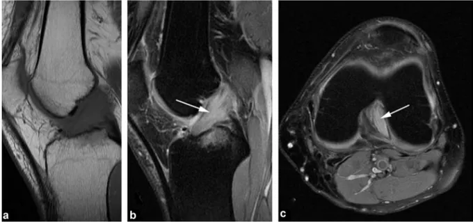
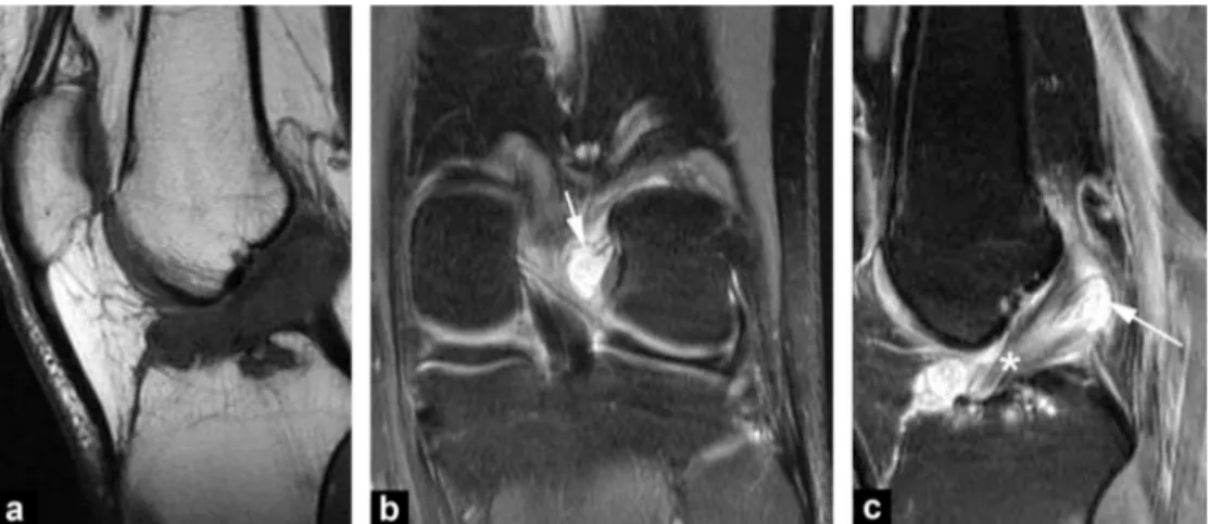
Figure 21. Cyst of the tent of the cruciate ligaments. MRI: T1-weighted sagittal (a), frontal (b) and sagittal (c) proton density views with fat saturation. Cystic formation (arrow) coming into contact with a cruciate ligament. The ACL is hyperintense (*) and poorly delineated as
Figure 22. Partial posterior cruciate ligament lesion (grade 1). MRI: proton density-weighted coronal view show only edema of the proximal insertion of the PCL with no loss of fiber continuity.
images recorded at 30◦flexion in which the PCL is tense can be used to make a diagnosis in the most difficult cases.
Finally, damage to the different structures of the postero-lateral angle point should always be looked for. These generally result in widening and a hyperintensity of the anatomical structure concerned. Surgery should be consid-ered to treat these injuries [50—53] in order to achieve optimal results.
Figure 23. Complete rupture of the posterior cruciate ligament. MRI: proton density sagittal view with fat saturation: the image is hyperintense and it is no longer possible to distinguish visible fibers (arrow).
Intra-articular ligament plasties
Several techniques are used depending on the injury and surgeons’ practices: an autologous patellar tendon intra-articular graft (the Kenneth—Jones technique) or plasty with an autologous tendon graft (gracilis and semitendinosus or the semitendinosus alone). Reconstruction techniques using a double bundle for reconstruction of the anterior cruciate ligament have developed more recently in order to preserve the dual function of the ligament[54].
Normal postoperative appearances
Despite the artefacts caused by metal materials, plasty gen-erally produces a weak homogeneous signal on MRI from two weeks after surgery[55,56], which shows no enhancement after intravenous administration of a gadolinium chelate (Fig. 24). During the first year, a transient increase in signal intensity is seen on T1-weighted and PD-weighted image signal due to revascularization and synovial prolif-eration[57]. After 12 months, the ligamentoplasty becomes homogeneous, and hypointense. Periarticular morphological and image signal abnormalities from the graft harvest sites (patellar tendon or pes anserinus tendon depending on the case) are always seen during the first year. Tunnelling in par-ticular causes bone change due to scarring around the graft, which may last long term for up to approximately a year. Resorbable polyglycolic acid screws disappear over 6 months to a year and replaced by fatty or fibrous tissue[58].
Pathological appearances of ACL ligament
plasties
MRI is indicated for recurrent instability, pain, restriction in joint movement or if a further injury occurs. Although a plasty hyperintensity may be physiological during the first year postoperatively, it should be considered to be
Figure 24. Normal findings after ligamenoplasty. On fat-suppressed Rhô weighted view, the plasty is homogeneous and hypointense.
pathological beyond this time and usually represents either impingement in the notch due to a repeated rupture (Fig. 25). The diagnosis of partial plasty rupture is difficult and requires a few residual fibers to be visualized. As in the case of partial rupture of the native ligament, the same indirect signs may help reach the diagnosis[59].
Periligament scarring reactions shows enhancement after intravenous administration of a gadolinium chelate and are frequently seen on follow-up MRI after ligamentoplasty. More rarely, reduced mobility is found when lesions of joint fibrosis contain excessive scarring. This classical ‘‘Cyclops syndrome’’ consists of a nucleus of fibrosis located in front of
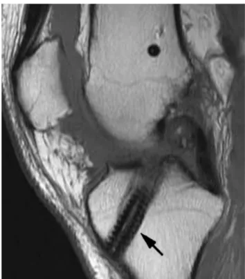
Figure 25. Rupture of a ligamentoplasty. T1-weighted sagittal MRI view: complete disappearance of the plasty fibers (arrow) indi-cating that it has ruptured. Interference screw (arrow) not hindering the interpretation.
the base of the plasty at the level of the intercondylar notch causing a residual flexion deformity (Fig. 26). MRI shows a fibrous hypointense nodule on all images with peripheral enhancement
Cystic graft degeneration (Fig. 27) is rare and should be suspected from a combination of pain and reduced joint amplitude.
Damage to collateral structure
The diagnosis of isolated damage is clinical although ultra-sound is often performed. The MRI appearances of these ligament lesions should however be understood as they very often accompany damage to the central pivot, menisci or traumatic or osteochondral lesions.
Medial collateral ligament
Three grades of injury may be distinguished during the acute phase[60,61]:
• grade 1 is a benign sprain: periligament hyperintense areas are seen with no fiber discontinuity (Fig. 28); • grade 2 is a moderate strain: MRI shows partial
disconti-nuity of the medial collateral ligament fibers (Fig. 29); • grade 3 is a severe sprain when complete ligament rupture
is present (Fig. 30): dysjunction of the capsule and menis-cus is confirmed if liquid has entered between the base of the meniscus and plane of the ligament which appears as an obvious hyperintensity on T2-weighted images not disappearing with fat saturation.
In the more chronic stage, the ligament appears thick-ened and is homogeneously hypointense representing its fibrous scarring.
The differential diagnoses are damages to other medial structures of the knee: the pes anserinus or semitendinosus, vastus medialis, femoral quadriceps or medial gastrocne-meous tendons.
Figure 26. Cyclops syndrome. MRI: T2-weighted sagittal view (a) and axial view (b). A large fibrotic hypointense nodule is present at the base of the anterior surface of the graft (arrows). The ‘‘notch plasty’’ appears inadequate creating impingement between the plasty the path of which is bayonet-shaped. The image is only partially affected by artefact due to the presence of a nearby metal interference screw.
Figure 27. Ballooning of the anterior cruciate ligamentoplasty.
Lateral collateral ligament
Damage to the fibular collateral ligament is less common and never occurs in isolation[62]. Radiologists should look for damage to the postero-lateral angle point combined with injuries of the popliteal tendon arcuate ligament (the postero-lateral reinforcement of the joint capsule), the ACL and PCL (Fig. 31). Rupture of the collateral fibular ligament usually occurs in the main body of the liga-ment or in its distal insertion and is usually complete. The small size of this ligament makes diagnosis of partial rupture practically impossible. Subchondral contusions or fractures to the medial compartment should be noted as
Figure 28. Grade 1 rupture of the medial collateral ligament. Proton density-weighted frontal view with fat suppression shows periligamentous edema.
should damage to the iliotibial band or the tendon of the femoral biceps. These complex lesions are a surgical semi-emergency which otherwise carry a major risk of residual instability.
The differential diagnoses to consider are damage to the patellar retinaculum (Fig. 32), isolated rupture of the popliteal tendon (very rare) or the iliotibial band syndrome (particularly in runners or cyclists). In the last of these situations, MRI (Fig. 33) shows a poorly defined T1-weighted hypointensity and hyperintense edema around the tendon on T2-weighted imaging with fat saturation which his easy to identify on axial sections[63,64].
Figure 29. Grade 2 rupture of the medial collateral ligament. MRI: T1-weighted coronal and axial views (a) and fat-suppressed Rhô view (b and c). Acute rupture of the distal insertion of a few of the medial collateral ligament fibers.
Figure 30. Grade 3 rupture of the medial collateral ligament. Fat-suppressed proton density-weighted frontal view. Acute rupture of the proximal insertion of the tibial collateral ligament fibers.
Figure 32. Rupture of the lateral retinaculum. MRI: T1-weighted sagittal view. The retinaculum is completely ruptured and displays severe thickening from scarring.
Figure 31. Lesion of the postero-lateral angle point. MRI: sagittal (a), frontal (b) and axial (c) Rhô views: complex lesion combining a rupture of the lateral collateral ligament, damage to the popliteal tendon and arcuate ligament and rupture of the anterior and posterior cruciate ligaments.
Figure 33. Iliotibial band lesion. MRI: frontal (a) and axial (b) sections: the iliotibial band is thickened (arrows) and contains hyperintense edema around the image.
Conclusion
Imaging investigations for meniscus and ligament injuries of the knee mostly involve MRI. A rigorous technique can diagnose all of the lesions, and particularly those liable to change treatment (particularly unstable meniscal lesions and partial rupture of the anterior cruciate ligament).
Take home messages
• MRI has become one of the best performing techniques for the diagnosis of meniscus and ligament injuries to the knee.
• MRI allows identify unstable meniscal lesions. • Specific image acquisition planes (fine axial oblique
proton density section obtained perpendicular to the axis of the ACL) can improve the diagnostic performance of MRI in partial ruptures of the anterior cruciate ligament.
Disclosure of interest
The authors declare that they have no competing interest.
References
[1]Hede A, Jensen DB, Blyme P, Sonne-Holm S. Epidemiology of meniscal lesions in the knee, 1215 open operations in Copen-hagen 1982—84. Acta Orthop Scand 1990;61:435—7.
[2]De Smet AA, Blankenbaker DG, Kijowski R, Graf BK, Shinki K. MR diagnosis of posterior root tears of the lateral meniscus using arthroscopy as the reference standard. AJR Am J Roentgenol 2009;192:480—6.
[3]Drapé JL, Godefroy D, Dupont AM, et al. Les limites de l’RM dans la pathologie méniscale. In: Le genou traumatique et dégénératif. GETROA OPUS XXIV. Montpellier: Sauramps Medi-cal; 1997. p. 379—409.
[4]Nizard R. Le diagnostic clinique d’une lésion méniscale est-il fiable? In: Le genou traumatique et dégénératif. GETROA OPUS XXIV. Montpellier: Sauramps Medical; 1997. p. 373—8.
[5]Beaufils P. A quoi sert le ménisque? Devenir des meniscec-tomies. In: Le genou traumatique et dégénératif. GETROA OPUS XXIV. Montpellier: Sauramps Medical; 1997. p. 365—72.
[6]Resnick D, Kang HS. Meniscal abnormalities. In: Resnick D, Kang HS, editors. Internal derangements of joints. Philadelphia: WB Saunders Company; 1997. p. 605—35.
[7]Brody JM, Hulstyn MJ, Fleming BC, Tung GA. The meniscal roots: gross anatomic correlation with 3-T MRI findings. AJR Am J Roentgenol 2007;188:446—50.
[8]Clark CR, Ogden JO. Development of the menisci of the human knee joint. J Bone Joint Surg 1983;65:538—47.
[9]Hauger O, Frank LR, Boutin RD, Lektrakul N, Chung CB, Haghighi P, et al. Characterization of the ‘‘red zone’’ of knee meniscus: MR imaging and histologic correlation. Radiology 2000;217:193—200.
[10]Sanders TG, Linares RC, Lawhorn KW, Tirman PF, Houser C. Oblique menisco-meniscal ligament: another potential pitfall for a meniscal tear — anatomic description and appearance at MR imaging in three cases. Radiology 1999;213:213—6.
[11]Sintsoff SA, Stallenberg B, Sintzoff S. Atypies, dysplasies et kystes méniscaux. In: Le genou traumatique et dégénératif. GETROA OPUS XXIV. Montpellier: Sauramps Medical; 1997. p. 395—409.
[12]Trillat A. Traumatic cracks du menisque interne du genou : clas-sification anatomique et diagnostic clinique. Rev Chir Orthop 1962;48:551—60.
[13]Lecas LK, Helms CA, Kosarek FJ, Garret WE. Inferiorly displaced flap tears of the medial meniscus: MR appearance and clinical significance. AJR Am J Roentgenol 2000;174:161—4.
[14]Van de Berg BC, Malghem J, Poilvache P, Maldague B, Lecou-vet FE. Meniscal tears with fragments displaced in notch and recesses of knee: MR imaging with arthroscopic comparison. Radiology 2005;234:842—50.
[15]Cargill AO, Jackson JP. Bucket handle tear of the medial menis-cus. J Bone Joint Surg 1976;58:248—51.
[16]Wright DH, De Smet AA, Norris M. Bucket handle tears of the medial and lateral menisci of the knee: value of MR imag-ing in detectimag-ing displaced fragments. AJR Am J Roentgenol 1995;165:621—5.
[17]Stoller DW, Martin C, Crues JV, Kaplan I, Mink JH. Menis-cal tears: pathologic correlation with MR imaging. Radiology 1987;163:731—5.
[18]Mackenzie R, Palmer CR, Lomas DJ, Dixon AK. Magnetic res-onance imaging of the knee: diagnostic performance studies. Clin Radiol 1996;51:251—7.
[19]Malghem J, Vande Berg BC, Lecouvet FE, Staumont V, Maldague B. Le genou dégénératif : menisci, os sous-chondral et tutti
quanti. Enseignement post-universitaire, 35. Société franc¸aise de radiologie. Formation médicale continue; 2004. p. 409—27.
[20]Cothran Jr RL, Major NM, Helms CA, Higgins LD. MR imag-ing of meniscal contusion in the knee. AJR Am J Roentgenol 2001;177:1189—92.
[21]Bikkina RS, Tujo CA, Schraner AB, Major NM. The ‘‘floating’’ meniscus: MRI in knee trauma and implications for surgery. AJR Am J Roentgenol 2005;184:200—4.
[22]Farley TE, Howell SM, Love KF, Wolfe RD, Neumann CH. Menis-cal tears: MR and arthrographic findings after arthroscopic repair. Radiology 1991;180:517—22.
[23]Sciulli RL, Boutin RD, Brown RR, et al. Evaluation of the postoperative meniscus of the knee: a study compar-ing conventional arthrography, conventional MR imagcompar-ing, MR arthrography with iodinated contrast material, and MR arthrog-raphy with gadolinium-based contrast material. Skeletal Radiol 1999;28:508—14.
[24]Applegate GR, Flannigan BD, Tolin BS, Fox JM, Del Pizzo W. MR diagnosis of recurrent tears in the knee: value of intra-articular contrast material. AJR Am J Roentgenol 1993;161: 821—5.
[25]White LM, Schweitzer ME, Weishaupt D, Kramer J, Davis A, Marks PH. Diagnosis of recurrent meniscal tears: prospective evaluation of conventional MR imaging, indirect MR arthrogra-phy, and direct MR arthrography. Radiology 2002;222:421—9.
[26]Magee T, Shapiro M, Rodriguez J, Williams D. MR arthrography of postoperative knee: for which patients is it useful? Radiology 2003;229:159—63.
[27]Petersen W, Zantop T. Partial rupture of the anterior cruciate ligament. Arthroscopy 2006;22:1143—5.
[28]Ravey JN, Dubois C, Pittet-Barbier L. Analyse bi-fasciculaire du LCA en IRM et application aux ruptures partielles. Monographie GETROA-SIMS; 2010 [opus XXXVII].
[29]Boutry N, Bourges M, Dupont S, Budzik J, Demondion X, Cotten A. Value of imaging in postero-lateral corner injuries of the knee. J Radiol 2009;90:681—91.
[30]Lerman JE, Gray DS, Schweitzer ME, Bartolozzi A. MR evalua-tion of the anterior cruciate ligament: value of axial images. J Comput Assist Tomogr 1995;19:604—7.
[31]Fealy S, Kenter K, Dines JS, Warren RF. Mucoid degeneration of the anterior cruciate ligament. Arthroscopy 2000;17:37.
[32]Mac Intyre J, Moelleken S, Tirman P. Mucoid degeneration of the anterior cruciate ligament mistaken for ligamentous tears. Skeletal Radiol 2001;30:312—5.
[33]Huang GS, Lee CH, Chan WP, et al. Acute anterior cruciate lig-ament stump entrapment in anterior cruciate liglig-ament tears: MR imaging appearance. Radiology 2002;225:537—40.
[34]Guenoun D, Le Corroller T, Amous Z, Pauly V, Sbihi A, Champ-saur P. The contribution of MRI to the diagnosis of traumatic tears of the anterior cruciate ligament. Diagn Interv Imaging 2012;93:331—41.
[35]Gentilli A, Seeger Ll, Yao L, Do HM. Anterior cruciate ligament tear: indirect signs at MR imaging. Radiology 1992;193:836—40.
[36]Fitzgerald SW, Remer EM, Friedman H, et al. MR evaluation of the anterior cruciate ligament: value of supplementing sagittal images with coronal and axial images. AJR Am J Roentgenol 1993;60:1233—7.
[37]Robertson PL, Schweitzer ME, Bartolozzi AR. Anterior cru-ciate ligament tears: MR imaging evalution. Radiology 1994;193:829—34.
[38]Kaplan PA, Walker CW, Kilcoyne RF, et al. Occult fracture patterns of the knee associated with anterior cruciate liga-ment tears: assessliga-ment with MR imaging. Radiology 1992;183: 835—8.
[39]Murphy BJ, Smith RL, Uribe JW, et al. Bone signal abnormalities in the postero-lateral tibia and the lateral femoral condyle in complete tears of the anterior cruciate ligament: a specific sign? Radiology 1992;182:221—4.
[40]Tung GA, Davis LM, Wiggins ME, Fadale PD. Tears of the anterior cruciate ligament: primary and secondary signs at MR imaging. Radiology 1993;188:661—7.
[41]Cobby MJ, Schweizer ME, Resnick D. The deep lateral femoral notch: an indirect sign of a torn anterior cruciate ligament. Radiology 1992;184:855—8.
[42]Vahey TN, Meyer SF, Shelbourne KD, Klootwyk TE. MR imag-ing of the anterior cruciate ligaments injuries. MRI Clin N Am 1994;2:365—80.
[43]Palle L, Reddy B, Reddy J. Sensitivity and specificity of verti-cally oriented lateral collateral ligament as an indirect sign of anterior cruciate ligament tear on magnetic resonance imag-ing. Skeletal Radiol 2010;39:1123—7.
[44]Costa-Paz M, Muscolo DL, Ayerza M, et al. Magnetic reso-nance imaging follow-up study of bone bruises associated with anterior cruciate ligament ruptures. Arthroscopy 2001;17: 445—9.
[45]Smith DK, May DA, Philips P. MR imaging of the cruciate lig-ament: frequency of discordant findings on sagittal obliques images and correlation with arthroscopic findings. AJR Am J Roentgenol 1996;166:411—3.
[46]Vahey TN, Broome DR, Kayes KJ, Shelbourne KD. Acute and chronic tears of the anterior cruciate ligament: differential features at MR imaging. Radiology 1999;181:251—3.
[47]Chen WT, Shih TT, Tu HY, et al. Partial and complete tear of the anterior cruciate ligament. Acta Radiol 2002;43:511—6.
[48]Sonin AH, Fitzgerald SW, Hoff FL, et al. MR imaging of the posterior cruciate ligament: normal, abnormal, and associated injury patterns. Radiographics 1995;15:551—61.
[49]Sonin AH, Fitzgerald SW, Friedman H, et al. Posterior cruciate ligament injury: MR imaging diagnosis and patterns of injury. Radiology 1994;190:455—8.
[50]Fanelli GC, Giannotti BF, Edson CJ. The posterior cruciate ligament arthroscopic evaluation and treatment. Arthroscopy 1994;10:673—88.
[51]Markolf KL, Graves BR, Sigward SM, Jackson SR, McAllister DR. How well do anatomical reconstructions of the postero-lateral corner restore varus stability to the posterior ligament-reconstructed knee? Am J Sports Med 2007;35:1117—22.
[52]Shelbourne KD, Jennings RW, Vahey TN. Magnetic resonance imaging of posterior cruciate ligament injuries: assessment of healing. Am J Knee Surg 1999;12:209—13.
[53]Vinson EN, Major NM, Helms CA. The postero-lateral corner of the knee. AJR Am J Roentgenol 2008;90:449—58.
[54]Casangrada BU, Maxwell NJ, Kavanagh EC, et al. Normal apperance and complications of double-bunble and selec-tive bundle anterior cruciate ligament reconstruction using optimal MRI techniques. AJR Am J Roentgenol 2009;192: 1407—15.
[55]Kulczycka P, Larbi A, Malghem J, Thienpont E, Vande Berg B, Lecouvet F. Imaging ACL reconstructions and their complications. Diagn Interv Imaging 2015;96:11—9.
[56] Viala P, Marchand P, Lecouvet F, Cyteval C, Beregi JP, Larbi A. Imaging of the postoperative knee. Diagn Interv Imaging 2016,
http://dx.doi.org/10.1016/j.diii.2016.02.008.
[57]Fantino O, Imbert JC, Borne J, Bordet B, Bousquet JC. Imag-ing of the postoperative knee in athletes: articular cartilage, menisci, and ligaments. J Radiol 2007;88:184—99.
[58]Bach FD, Carlier RY, Elis JB, et al. Anterior cruci-ate ligament reconstruction with bioabsorbable polyglycolic acid interference screws: MR imaging follow-up. Radiology 2002;225:541—50.
[59]Horton LK, Jacobson JA, Lin J, Hayes CW. MR imaging of anterior cruciate ligament reconstruction graft. AJR Am J Roentgenol 2000;75:1091—7.
[60]Recondo JA, Salvador E, Villanua JA, et al. Lateral stabiliz-ing structures of the knee: functional anatomy and injuries assessed with MR imaging. Radiographics 2000;20:S91—102.
[61] Ruiz ME, Erickson SJ. Medial and lateral supporting structures of the knee. Normal imaging anatomy and pathologic findings. MRI Clin N Am 1994;2:381—99.
[62] Juhng SK, Lee JK, Choi SS, Yoon KH, Roh BS, Won JJ. MR evalu-ation of the ‘‘arcuate’’ sign of postero-lateral knee instability. AJR Am J Roentgenol 2002;18:583—8.
[63]Muhle C, Ahn JM, Yeh L, et al. Iliotibial band friction syndrome: MR imaging findings in 16 patients and MR arthro-graphic study of six cadaveric knees. Radiology 1999;212: 103—10.
[64]Nishimura G, Yamato M, Tamai K, et al. MR findings in iliotibial band syndrome. Skeletal Radiol 1997;26:533—7.