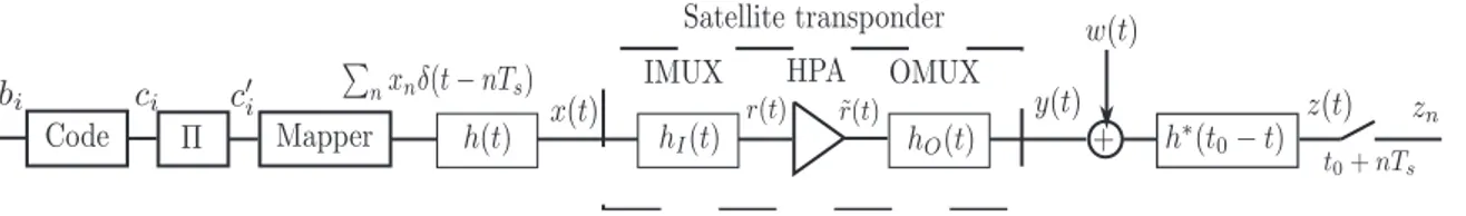
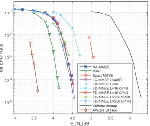
A comparison of iterative receivers for the non linear satellite channel
Texte intégral
Figure
Documents relatifs
A com- parison of Multiple Non-linear regression and neural network techniques for sea surface salinity estima- tion in the tropical Atlantic ocean based on satellite data.. CMACS
In the frequency domain, the third moment of the response of a linear oscillator subjected to a random loading is the result of the double integration of the bispectrum of the
The selected AMSU-B and AMSU-A pixels were radiance-averaged for all channels and associated to the UTH values derived from the corresponding radiosonde profiles.. Once the
In table (1), we compare the average number of iterations to get the demanded accuracy on the linear problem (1) for 4 iterative methods : the proposed method (PM), the
the analogy by comparing time and frequency domain measurements of the mechanical response in the non-linear regime and under the in uence of external, gate-controlled frequency
al, “Multicarrier digital predistortion/equalization techniques for non-linear satellite channels,”in Proc.. 30th
A non-linear modal analysis method has been proposed; it is based on the concept of complex non-linear modes and on a frequency-domain formulation of the eigenproblem associated
