En vue de l'obtention du
DOCTORAT DE L'UNIVERSITÉ DE TOULOUSE
Délivré par :
Institut National Polytechnique de Toulouse (Toulouse INP)
Discipline ou spécialité :
Informatique et Télécommunication
Présentée et soutenue par :
M. CHARLES-UGO PIAT-DUROZOIle mardi 27 novembre 2018
Titre :
Unité de recherche : Ecole doctorale :
Nouvelle forme d'onde et récepteur avancé pour la télémesure des futurs
lanceurs
Mathématiques, Informatique, Télécommunications de Toulouse (MITT)
Institut de Recherche en Informatique de Toulouse (I.R.I.T.)
Directeur(s) de Thèse :
MME MARIE LAURE BOUCHERET M. CHARLY POULLIAT
Rapporteurs :
M. EMMANUEL BOUTILLON, UNIVERSITE DE BRETAGNE SUD M. FREDERIC GUILLOUD, IMT ATLANTIQUE
Membre(s) du jury :
M. CHRISTOPHE JEGO, UNIVERSITÉ DE BORDEAUX, Président M. CHARLY POULLIAT, INP TOULOUSE, Membre
Mme MARIE LAURE BOUCHERET, INP TOULOUSE, Membre Mme NATHALIE THOMAS, INP TOULOUSE, Membre
L’aspiration à la vérité est plus précieuse que l’assurance de sa possession.
−Gotthold Lessing.
Des chercheurs qui cherchent, on en trouve; Des chercheurs qui trouvent, on en cherche.
−Générale De Gaulle. Vous me donnerez votre avis à la lecture de ce manuscrit.
Remerciements
Je tiens à remercier mes directeurs de thèse Monsieur Charly Poulliat, Madame Nathalie Thomas et Madame Marie-Laure Boucheret pour leur aide et leurs conseils prodigués pendant la thèse. Plus particulièrement, je remercie Charly pour son abnégation envers ses thésards, sa disponibilité, ses éclairages et ses intuitions qui ont été déterminants dans l’avancement de ma thèse. Également, Nathalie qui fut disponible et pertinente lors des nombreuses relectures et points d’avancements. Enfin je remercie Marie-Laure pour son aide et son expertise apportée lors de la thèse. Mes remerciements vont également à mes encadrants du Centre National d’Étude Spatial (CNES) Monsieur Guy Lesthievent et Monsieur Emmanuel Bouisson.
Je remercie le CNES et l’Institut de Recherche en Informatique de Toulouse (IRIT) pour avoir financé cette thèse.
Je remercie le laboratoire Télécommunication Spatiales et Aéronautiques (TéSA) pour le cadre de travail formidable dont j’ai bénéficié pendant la thèse.
Je souhaite remercier Monsieur Christophe Jego pour avoir accepté de présider ma sou-tenance de thèse. Également, Monsieur Frédéric Guilloud et Monsieur Emmanuel Boutillon pour avoir rapporté ma thèse.
Enfin je souhaiterai remercier tous les membres du TéSA, Romain, Simonet, Barbara, Selma, Julien, Lorenzo, Sylvain, Adrien, Antoine, Raoul, Philippe, Serge, Bernard, Patrice,
Jacques, Isabelle, Jean-Yves, Corinne... avec qui j’ai vécu trois merveilleuses années. L’environnement de travail au TéSA fut très agréable et les pauses animées du matin me manqueront. J’espère
que j’aurais l’occasion de revenir de temps en temps au laboratoire. Pour finir je remercie mes parents qui m’ont soutenu dans le choix de m’orienter vers une thèse, mes cinq frères et soeurs qui étaient toujours curieux et préoccupés de l’avancement de mes travaux et Marianne de m’avoir supporté durant ces trois dernières années (et ce n’est que le début...).
Résumé
Les modulations à phase continue (CPMs) sont des methodes de modulations robuste à la non-cohérence du canal de propagation. Dans un context spatial, les CPM sont utilisées dans la chaîne de transmission de télémesure de la fusée. Depuis les années 70, la modulation la plus usitée dans les systèmes de télémesures est la modulation CPFSK continuous phase frequency
shift keying filtrée. Historiquement, ce type de modulation est concaténée avec un code
Reed-Solomon (RS) afin d’améliorer le processus de décodage. Côté récepteur, les séquences CPM non-cohérentes sont démodulées par un détecteur Viterbi à sortie dure et un décodeur RS. Néanmoins, le gain du code RS n’est pas aussi satisfaisant que des techniques de codage moderne capables d’atteindre la limite de Shannon. Actualiser la chaîne de communication avec des codes atteignant la limite de Shannon tels que les codes en graphe creux, implique de remanier l’architecture du récepteur usuel pour un détecteur à sortie souple. Ainsi, on propose dans cette étude d’ élaborer un détecteur treillis à sortie souple pour démoduler les séquences CPM non-cohérentes. Dans un deuxième temps, on concevra des schémas de pré-codages améliorant le comportement asymptotique du récepteur non-cohérent et dans une dernière étape on élabora des codes de parité à faible densité (LDPC) approchant la limite de Shannon.
Abstract
Continuous phase modulations (CPM) are modulation methods robust to the non-coherency of
propagation channels. In a space context, CPMs are used in the communication link between the rocket and the base stations. Since the 70’s, the most popular telemetry modulation is the filtered continuous phase frequency shift keying (CPFSK). Traditionally, the CPFSK scheme is concatenated with a Reed-Solomon (RS) code to enhance the decoding process. At the receiver side, the non-coherent CPM sequences are demodulated through a hard Viterbi detector and a RS decoder. However, the RS’s coding gain is no more satisfactory when directly compared to modern coding schemes enable to reach the Shannon limit. Updating the communication link to capacity achieving codes, as sparse graph codes, implies to redesign the receiver architecture to soft detector. In that respect, we propose in this study to design a trellis-based soft detector to demodulate non-coherent CPM sequences. In a second part, we will elaborate precoding schemes to improve the asymptotic behaviour of the non-coherent receiver and in a last step we will build low density parity check codes approaching the Shannon limit.
Contents
Table des sigles et acronymes xix
Introduction (French) 1
Introduction 9
1 Continuous Phase Modulation 19
1.1 Résumé . . . 19 1.2 Introduction . . . 20 1.3 CPM signal . . . 22 1.4 Trellis Representation . . . 27 1.5 Rimoldi’s Decomposition . . . 29 1.6 CPM Receivers . . . 34 1.7 Conclusion . . . 42
2 On the link between coherent and non-coherent receivers 45 2.1 Résumé . . . 46
2.2 Introduction . . . 47
2.3 System model . . . 48
2.5 Non-coherent TBR: a novel approach . . . 59
2.6 Complexity computation . . . 61
2.7 Asymptotic Analysis . . . 63
2.8 Simulation results . . . 67
2.9 Phase deviation and frequency synchronization . . . 68
2.10 Conclusion . . . 72
3 CPM Precoding schemes 73 3.1 Résumé . . . 74
3.2 Introduction . . . 75
3.3 Extrinsic Information Transfer Chart . . . 76
3.4 Precoding for maximization of the BICM capacity . . . 81
3.5 A novel approach for non-binary CPM precoding for coherent detection . . . 87
3.6 A novel approach to non-coherent precoding . . . 92
4 CPM coding schemes 101 4.1 Résumé . . . 101
4.2 Introduction . . . 102
4.3 Serially concatenated coded CPM scheme . . . 104
4.4 Introduction to LDPC codes . . . 105
4.6 Binary LDPC codes for coherent and noncoherent channel . . . 117
4.7 Capacity achieving without iterative decoding for M-ary CPM . . . 127
Conclusions et perspectives 131
Conclusions and perspectives 137
A A detail proof of the link between coherent and non-coherent receivers 141
B A detail proof of the novel non-coherent MAP receivers 149
List of Figures
1.1 (a.) Frequency pulse (b.) Phase response. . . 24
1.2 Binary 2GMSK h = 1/2, BT = 0.25 (a.) Amplitude (b.) Envelop. . . . 25
1.3 RC (a.) quaternary L = 3 (b.) binary h = 0.5 . . . . 27
1.4 (a.) PSD of various CPM M = 2, h = 0.5 (b.) GSMK BTs = 0.5, M = 2, L = 2 28
1.5 Modulo 2π Phase Tree of 1RC . . . 30
1.6 Block diagram of CPM system (CPE and MM). . . 31
1.7 Continuous phase modulator. . . 32
1.8 Recursive implementation of MSK following the CPE and MM representation. 33
1.9 Complex matched filters of M-CPM modulation . . . 36
1.10 TBR States Diagram . . . 37
1.11 SER of (a.) GMSK h = 1/2, BT = 0.3 L = 1 and (b.) CPFSK L = 1, M = 4,
h = 5/7 . . . . 42
1.12 Spectral Efficiency of (a.) GMSK h = 1/2, BT = 0.3 L = 1 and (b.) CPFSK
L = 1, M = 4, h = 5/7 . . . . 43
2.1 TBR Extended State Space Model for N=3 and L=2 . . . 51
2.2 Non-coherent TBR State Space Model for N=3 and L=2 . . . 59
2.3 (a) EXIT charts: 2GMSK h = 1/2, M = 2 and BT = 0.25 and 2RC with
h = 1/4, M = 4 (N = 3 for both) (b). BER: 2GMSK with h = 1/2, M =
2.4 SE of (a.) binary GMSK with h = 1/2, L = 2 and BT = 0.25 (b.) quaternary 2RC with h = 1/4. . . . 70
2.5 Impact of (a.) phase deviation (b.) frequency synchronization in non-coherent regime over a binary GMSK, Eb/N0 = 12.8 dB (h = 1/2 and L = 2) . . . 71
3.1 SISO Decoder . . . 77
3.2 EXIT charts Binary 1REC h = 1/2 Eb/N0 = 0 dB (a.) Information Rate (b.)
Precoding Effect . . . 83
3.3 binary 2CPM (Q = 2) CPE diagram . . . . 85
3.4 Exit charts of (a.) binary 2GMSK (h = 0.5) (b.) quaternary 2GMSK (h = 0.25,
BT = 0.5) for Es/N0 = 0 dB . . . 85
3.5 quaternary 2GMSK (h = 0.25, BT = 0.5) CPE diagram . . . . 87
3.6 CPE diagram quaternary CPM with F = [3 3], L = 2 and Q = 4 . . . 89
3.7 3REC h = 1/2 M = 2 and 2REC h = 1/4, M = 4 (a.) Binary EXIT charts at
Es/N0= 0 dB (b.) Spectral Efficiency . . . . 90
3.8 2REC h = 1/4, M = 4, RC h = 1/4 M = 4 (a.) Non-binary EXIT charts at
Es/N0= 0 dB (b.) Spectral Efficiency . . . . 90
3.9 SER : 3REC h = 1/2 M = 2, 2REC h = 1/4, M = 4 and RC h = 1/4 M = 4 92
3.10 NC binary 2GMSK (h = 0.5 and BT = 0.5) (a.) F = [0 0] (b.) F = [1 1] . . . 93
3.11 CPE diagram quaternary CPM with F = [1 3 1 3], L = 2, Q = 4 and N = 3 . 94
3.12 (a.) EXIT charts NCB-precoding CPFSK h = 5/7 and M = 2 (b.) non-binary EXIT charts NCNB-precoding CPFSK h = 3/4 and M = 4 . . . . 96
3.14 Exit charts of NCB-precoding systems (a.) binary GMSK with h = 1/2, L = 2
and BT = 0.25 (b.) quaternary 2RC with h = 1/4 . . . . 99
3.15 NC BER of NCB-precoding systems (a.) binary GMSK with h = 1/2, L = 2 and BT = 0.25 (b.) quaternary 2RC with h = 1/4 . . . . 100
4.1 Coded interleaved CPM scheme with iterative decoding . . . 104
4.2 Tanner graph binary LDPC code . . . 106
4.3 Variable node update . . . 108
4.4 Check node update . . . 108
4.5 Tanner graph non-binary LDPC code . . . 110
4.6 Variable node update . . . 112
4.7 Check node update . . . 113
4.8 CPFSK M = 4 and h = 5/7 (≈ 0.715) (a.) Exit charts (b.) Spectral Efficiency 119 4.9 Coded BER: quaternary CPFSK with h = 5/7, N = 3 and R = 1/2. . . . 121
4.10 Binary EXIT charts: CPFSK h = 5/7, M = 4, 2GMSK h = 1/2, M = 2, BT = 0.3 and 2RC h = 1/4, M = 4 . . . . 124
4.11 Information Rate (a.) 2GMSK h = 1/2, M = 2, BT = 0.3 N = 2 (b.) CPFSK h = 5/7, M = 4, N = 3 . . . 125
4.12 Information Rate 2RC h = 1/4, M = 4, N = 2 . . . . 126
4.13 Non-binary EXIT charts (R = 1/2) (a.) RC with h = 1/4 and M = 4 and (b.) 2REC with h = 1/4 and M = 4. . . . 128
4.14 Information Rate (R = 1/2) (a.) RC with h = 1/4 and M = 4 and (b.) 2REC with h = 1/4 and M = 4. . . . 129
A.1 TBR Extended State Space Model for N=3 and L=2 . . . 141
List of Tables
1.1 CPM schemes and their frequency pulse . . . 23
1.2 Set of parameters of Fig.1.1 . . . 24
2.1 Comparison with main existing approaches. . . 50
3.1 CPM optimal matrix for NCB-precoding . . . 98
4.1 LDPC optimization procedure . . . 116
4.2 Summation of coding scheme stability . . . 120
4.3 Degree distribution used in Fig.4.9 (dvmin≥ 2,R = 1/2). . . . 120
4.4 Degree distribution binary LDPC (R = 1/2). . . . 124
4.5 Summation of coding scheme stability with precoding scheme . . . 126
Table des sigles et acronymes
LLR Log-likelihood ratios
TBR Trellis-based receiver
BICM Bit-interleaved coded modulation
EXIT Extrinsic information transfer
NC Non-Coherent
NB Non-Binary
BER Bit error rate
DE Density evolution
SPA Sum-Product Algorithm
BP Belief Propagation algorithm
SISO Soft-Input Soft-Output
ML Maximum Likelihood
MAP Maximum A Posteriori
RS Reed-Solomon
CPFSK Continuous Phase Frequency Shift Keying
FM Frequency Modulation
PM Phase Modulation
CCSDS Consultative Committee for Space Data Systems
GMSK Gaussian Minimum Sift Keying
MSK Minimum Sift Keying
MSK Frequency Sift Keying
SOQPSK-TG Shaped Offset Quadrature Phase Shift Keying-Telemetry Group
SNR Signal to Noise Ratio
Introduction (French)
Contexte
Le vol de la fusée est entièrement pré-programmé avant le lancement. Par conséquent, après la mise à feu des réacteurs, la trajectoire du lanceur ne peut plus être rectifiée. La seule contre-mesure encore disponible est l’auto-destruction afin d’empêcher la fusée de s’abîmer sur des zones sensibles. Aux États-Unis, cette contre-mesure suit un cahier des charges rigoureux cer-tifié par le 45th Space Wing de l’US Air Force. Afin de prendre cette décision irrémédiable, le lanceur doit informer le sol d’hypothétiques dysfonctionnements. Hormis ce scénario catastro-phe, il est nécessaire que les opérateurs puissent suivre scrupuleusement les comportements de la fusée durant le vol. Ainsi, le système de télémémesures embarqué sur le lanceur transmet au sol de nombreuses données provenant des capteurs. Ensuite, les données sont enregistrées et traitées par les opérateurs sol. Au long de ce manuscrit, on se focalisera davantage sur le système de communication de la télémesure entre la fusée et le sol. Historiquement dans le domaine aéronautique et spatial, le système de télémémesures (TM) est une application requérant un faible débit d’environ 1Mbps en bande S. Ce débit décroît généralement avec l’éloignement de la fusée au cours du vol. Afin de garder le lien de communication ouvert pendant le vol, des stations de base sont positionnées le long de la trajectoire de la fusée. Ces stations enregistrent généralement plusieurs jeux de données identiques provenant du lanceur. En effet plusieurs antennes TM sont disposées sur la fusée avec une diversité de polarisation (Circulaire droite/gauche) ou de fréquence selon les cas. L’idée d’une telle archi-tecture est de minimiser les risques d’une perte totale du lien de la communication entre le sol et la fusée. Ce risque est d’autant plus grand que le canal de propagation est souvent perturbé.
Canal de propagation
Le canal de propagation entre le lanceur et le sol est un milieu très perturbé surtout pendant les phases de transition: allumage moteur, séparation des moteurs, de la coiffe... Ces phases génèrent des vibrations qui parcourent la fusée. Ce phénomène entraîne une dégradation du signal transmis. Un autre phénomène impactant le canal est les effets de flamme. Ces effets apparaissent lorsque le signal passe derrière les réacteurs de la fusée. Ce phénomène provoque une dérive de la phase voir même des sauts de la phase pendant la transmission. On appelle canal non-cohérent un canal de propagation entrainant une rotation de phase (par opposition au canal cohérent). Ces phénomènes accumulés peuvent conduire à une perte totale du lien de communication. Par conséquent, les méthodes de modulation utilisées dans le système de télémesures doivent être suffisamment robustes à de telles contraintes.
Modulation à phase continue
Historiquement les modulations adoptées pour la télémesure sont des modulations de fréquence (FM) et/ou de phase (PM). Elles sont plus connues sous le nom de modulation à phase
con-tinue. Cette classe de modulations est robuste aux dérives de phase et aux distorsions
non-linéaires générées par l’amplificateur lorsqu’il est poussé à sa puissance maximale de sortie. Depuis les années 70, la modulation la plus usitée dans les systèmes de télémesures est la modulation par impulsions et codage PCM/FM aussi appelée la continuous phase frequency
shift keying (CPFSK) filtrée. Cependant la multiplication des capteurs, entraînant un besoin
pressant pour le haut débit, rend ce type de modulation de plus en plus obsolète. De plus, les détecteurs CPFSK des standards de télémesure ne sont pas adaptés aux codes correcteurs à entrées souples ce qui limite le gain de codage atteignable par rapport aux techniques de codage moderne. Récemment, le Range Commanders Council (RCC) a proposé une série de standards pour la télémesure afin de favoriser la compatibilité des équipements en transmis-sion, réception et traitement du signal dans le rapport IRIG Standard 106-17 [Iri]. Ce rapport suggère de remplacer la CPFSK par d’autres modulations comme la shaped offset quadrature
phase shift keying - telemetry group (SOQPSK-TG). De même le Consultative Committee for Space Data Systems (CCSDS) développa une série de recommandations sur des techniques de
modulation pour optimiser les largeurs de bande du standard de la télémesure pour des mis-sions nécessitant du haut débit tel que la Gaussian Minimum Shift Keying (GMSK) précodée ou l’OQPSK filtrée. Un désavantage majeur des modulations OQPSK est que l’information utile est exclusivement comprise dans la phase donc si un déphasage d’une quantité inconnue se produit il est difficile de démoduler de manière non-cohérente. Généralement le déphasage est alors évalué récursivement pour permettre la démodulation. Dans le cas d’une modulation CPM classique, les bits d’information sont encodés dans la trajectoire de phase et décodés par un récepteur dit non-cohérent.
Récepteur non-cohérent
Un canal de transmission caractérisé par un déphasage est appelé non-cohérent. Pour dé-moduler des séquences de manière non-cohérentes, les stations sol doivent être équipées de récepteurs dit non-cohérents. Certains de ces récepteurs fonctionnent sur le même principe que les détecteurs cohérents excepté que l’information de phase est inaccessible. Les récep-teurs non-cohérents se distinguent des cohérents de part leurs métriques de branches. Les métriques non-cohérentes sont calculées en moyennant les métriques cohérentes sur la phase. Deux approches existent pour démoduler une séquence non-cohérente: soit par bloc soit par treillis. La détection par bloc est plus robuste aux sauts de phases que le treillis mais est moins performante. [RD99][VCT10] implémentèrent le récepteur par bloc et [DS90][CFR00] celui par treillis. Ces détecteurs sont évidemment moins performants que le récepteur cohérent mais ils peuvent s’approcher des résultats du cohérent en augmentant fortement la fenêtre d’observation. Historiquement dans les standards de la télémesure, le processus de décodage est amélioré par la concaténation de la CPFSK avec un code Reed-Solomon (RS) [RS60]. Cependant, le gain de codage d’un code RS n’est pas aussi satisfaisant que ceux utilisés dans les techniques de codages modernes.
Schéma de codage
Berrou et al. [BG96] révolutionnèrent le domaine du codage en 1993. Ces derniers proposèrent un schéma de codage fonctionnant proche de la limite de Shannon. Le principe est de con-caténer deux codes convolutifs séparés par un entrelaçeur et d’effectuer un décodage itératif joint. Le décodage joint fonctionne en connectant la sortie d’une premier code avec l’entrée du second et vise versa. Cette classe de code est appelée Turbo-Codes. Les Turbo-Codes sont bien adaptés aux modulations sans mémoire cependant ils deviennent redondants lorsqu’ils sont associés aux modulations CPM. En effet, il est possible d’effectuer un décodage itératif joint directement entre le code convolutif et le démodulateur CPM. Une autre classe de codes fonctionnant proche de la capacité de Shannon est la classe des codes de parité à faible den-sité appelés LDPC. Ils sont aussi performants que les turbo-codes tout en ayant une faible complexité de décodage. De plus, des études récentes ont montré que cette classe de codes est bien adaptée aux CPM [Ben15]. Ainsi on privilégiera, au long de ce manuscrit, le système composé de la concaténation série d’un code LDPC avec une modulation CPM. En revenant à notre contexte, ce schéma de codage devra convenir à la démodulation non-cohérente. Par ailleurs, il serait intéressant d’avoir un schéma de codage adapté à la fois au régime cohérent et non-cohérent ainsi il ne sera pas utile de modifier le codage au cours de la transmission suivant la cohérence du canal. Cependant, cela nécessite d’avoir des récepteurs avec des fonctions de transfert d’information mutuelle proches dans les deux régimes, ce qui est rarement le cas. Un moyen de changer la fonction de transfert sans modifier les performances du récepteur est d’utiliser un schéma de pré-codage.
Schéma de pré-codage
Le pré-codage, associé à la CPM en régime cohérent, fut étudié dans de précédents travaux. [Ben+07]; [Per+10] proposèrent un pré-codage permettant d’atteindre le débit maximal sans itérer entre les schémas de codage. L’idée consiste essentiellement à changer le mapping entre les symboles d’information et les trajectoires de la CPM. Ainsi le débit maximal est
atteint sans itérer, et plus encore, le pré-codage change la forme de la fonction de transfert du démodulateur CPM sans perte de performances. Cependant, cette méthode est efficace uniquement pour les CPM binaires et n’est pas directement applicable au récepteur non-cohérent. Par conséquent, deux axes d’amélioration sont possibles:
1. élaborer une classe de pré-codages applicables quelque soit la cohérence du canal 2. sélectionner ceux de cette classe générant une fonction de transfert de l’information mutuelle proche dans les deux régimes.
Structure du manuscrit et principales contributions
Dans ce manuscrit, on souhaite élaborer un détecteur CPM treillis basé sur une démodulation de type MAP en régime non-cohérent avec de bons gains de codage. L’application principale est le lien de communication entre le système de télémesures de la fusée et le sol. L’organisation de cette thèse et les principales contributions sont résumées ci-dessous.
Chapitre 1: Ce chapitre est un chapitre d’introduction à la CPM [Pro][AAS13] et aux récepteurs cohérent et non-cohérent qui lui sont associés. Dans un premier temps, on passe en revue tous les paramètres du signal CPM et leurs effets sur le spectre. Puis on présente le treillis originellement associé à la CPM [ARS81a][ARS81b] et les améliorations apportées par la décomposition de Rimoldi [Rim88]. Dans une dernière étape, on décrit les différentes méthodes existantes pour démoduler la CPM en régime cohérent et non-cohérent. Dans cette thèse, les contributions sont principalement sur la détection non-cohérente, ainsi on ne présente que le détecteur MAP treillis en régime cohérent. En régime non-cohérent, on aborde deux types d’approches pour démoduler des séquences CPM: soit par bloc soit par treillis. Les détecteurs treillis non-cohérents furent élaborés au travers de deux références majeures: [DS90] pour le cas ML et [CFR00] pour le critère MAP. La détection par bloc, pour sa part, fut formulée dans [RD99] et [VCT10]. Les résultats de ce chapitre ont été publiés dans:
Bouisson, E., & Lesthievent, G. (2017, Sept). Détection non-cohérente souple par bloc ou à mémoire des CPM. In Groupe de recherche sur le traitement du signal (GRETSI), Juan-Les-Pins France.
• Conférence Internationale: Piat-Durozoi, C. U., Poulliat, C., Boucheret, M. L., Thomas, N., Bouisson, E., & Lesthievent, G. (2017, March). Multisymbol with memory nonco-herent detection of CPFSK. In Acoustics, Speech and Signal Processing (ICASSP), 2017 IEEE International Conference on (pp. 3794-3798). IEEE. New-Orleans USA.
Chapitre 2: Dans ce chapitre, on étudie le récepteur treillis non-cohérent. Précédemment, on a mis en lumière un désaccord entre les deux références majeures [DS90] et [CFR00] au sujet de l’espace d’état utilisé pour démoduler des séquences CPM non-cohérentes. Il apparaît que la cardinalité des états proposée pour la détection MAP [CFR00] est plus importante que celle introduite en [DS90] pour la détection ML. En effet, l’auteur en [CFR00] ajouta à l’espace d’état fourni en [DS90] l’information de phase générant un modèle étendu. Ainsi, on étudie dans ce chapitre le bénéfice et/ou la nécessité de cet écart en redérivant complètement les équations de la détection non-cohérente basée sur l’algorithme BCJR. On montre finalement que l’espace d’état étendu peut être réduit à la même formulation que [DS90] sans perte de performance. Cependant le model à espace d’état redondant est utlisable par les deux types de récepteurs (cohérent et non-cohérent). Par la suite, on propose de rectifier la formulation du détecteur non-cohérent MAP proposé en [CFR00] avec la formulation de l’espace d’état optimal donné en [DS90]. Les contributions de ce chapitre ont été publiées dans:
• Journal: Piat-Durozoi, C. U., Poulliat, C., Boucheret, M. L., Thomas, N., Bouisson, E., & Lesthievent, G. Minimal state non-coherent symbol MAP detection of Continuous-Phase-Modulations. IEEE Communication Letter, 2018.
Chapitre 3: Dans ce chapitre, on se propose d’ajuster le comportement asymptotique de la CPM avec les contraintes du canal afin de maximiser les gains de codage. Le comportement asymptotique de la CPM est différent suivant que le régime soit cohérent ou non-cohérent.
En effet, la plupart des CPM utilisées présentent une fonction de transfert d’information mutuelle convergeant vers le point (1, 1) en cohérent alors que ce n’est plus le cas en régime non-cohérent. Ainsi, les schémas de codage classiques (convolutif, LDPC) génèrent une pé-nalité de capacité et/ou un palier d’erreur en régime non-cohérent. Pour répondre à cette problématique, un pré-codage est élaboré. Ce dernier force la convergence de la fonction de transfert vers le point de coordonnées (1, 1). Le pré-codage consiste essentiellement à changer le mapping entre les symboles d’information et les trajectoires de la CPM. Ce pré-traitement préserve le débit maximal atteignable tout en permettant un décodage itératif efficace. La contribution de ce chapitre a été publiée dans:
• Conférence Internationale: Piat-Durozoi, C. U., Poulliat, C., Boucheret, M. L., Thomas, N., Bouisson, E., & Lesthievent, G (2018, October). Precoding for Non-coherent detec-tion of continuous phase moduladetec-tions. MILCOM, 2018 in process, Los-Angeles Califor-nia USA.
• Journal: Piat-Durozoi, C. U., Poulliat, C., Boucheret, M. L., Thomas, N., Bouisson, E., & Lesthievent, G. A novel nonbinary precoding for continuous phase modulations. En préparation.
Chapitre 4: Dans ce chapitre, on élabore des schémas de codage concaténés en série avec une modulation CPM qui donnent de bon gains pour les deux régimes. On se concentre principalement sur les codes de parité à faible densité (LDPC) sur GF(q). On a montré aux chapitres 2 et 3 que la fonction de transfert de l’information mutuelle à la sortie du détecteur non-cohérent dépendait de la cohérence du canal. En effet, dans le cas cohérent, la plupart des CPM ont une information mutuelle atteignant le point (1, 1) alors que ce n’est plus le cas en régime non-cohérent si aucun pré-codage n’est considéré. Par conséquent, les profils et la condition de stabilité des codes en graphes creux seront différents d’un régime à l’autre. En fait, il apparaît qu’un schéma de codage élaboré pour le cas cohérent ne peut être utilisé en régime non-cohérent puisque les profils ne remplissent pas la condition de stabilité. Au contraire, un code conçu pour le non-cohérent est toujours stable en régime cohérent mais au
prix d’une perte de performance. En fait, pour avoir un schéma de codage opérant pour les deux canaux, il semble raisonnable d’élaborer en premier lieu un schéma de codage pour le cas le plus contraignant puis d’évaluer ces performances dans le cas le moins contraint. La contribution de ce chapitre a été publiée dans:
• Conférence Internationale: Piat-Durozoi, C. U., Poulliat, C., Thomas, N., Boucheret, M. L., & Lesthievent, G. (2017, June). On sparse graph coding for coherent and non-coherent demodulation. In Information Theory (ISIT), 2017 IEEE International Sym-posium on (pp. 2905-2909). IEEE, Aachen Germany.
Introduction
Context
Flight phases of the launcher are entirely preprogrammed before take off. Consequently, af-ter the engine-ignition, the rocket trajectory can not be rectified. The only counaf-termeasure available is the self-destruction to prevent the rocket to crash over sensitive areas. In USA this countermeasure follows thorough and strict specifications certified by the 45th Space
Wing of the US Air Force. To take such decision, the launcher must inform the ground
sta-tion of hypothetical failures. Apart from such a worst case scenario, it is important to the ground operators of having a full tracking of the rocket behaviour during the different flight phases. In that respect, the Telemetry System on-board the launcher transmits a wide variety of data coming from its sensors to the ground stations. Afterwards, the data are recorded and processed on ground by the operators. Along this manuscript, we focus more specifi-cally on the communication unit between the rocket and the ground station. Traditionally in space/aeronautical domain, the telemetry (TM) is an application requiring low data rate, around 1Mbps in S-band. This rate usually decreases over the course of the rocket. To keep the communication link open over the flight, ground stations are positioned along the path of the launcher. Those stations may acquire several identical sets of data coming from the launcher. Indeed quite a few TM antennas are set in opposed position on the rocket with a polarization diversity (Right/Left Hand Circular ) or frequency diversity. The idea is to reduce the risk of a total communication loss by enabling multiple sights between the ground station and the rocket. This risk is significant because of the propagation channel features.
Propagation channel
The propagation channel between the launcher and the ground is very disturbed especially during the transitional phases as: engine-ignition, boosters separation, rocket’s nose separa-tion... Actually, those phases generate a lot of vibration spreading over the launcher. This phenomenon leads to impairments of the rocket’s signal during the transmission. Another phenomenon impacting the channel is called the Flame Effects. Those effects appear when the transmitted signal goes on behind the rocket’s engine. As a result, the signal undergoes a phase shift or even phase hopping during the transmission. Usually, transmission channels incurring unknown phase shift are called non-coherent (by opposition to coherent channel). This set of phenomenons may lead to a total loss of the communication link. Consequently, modulations methods used in such transmissions must be sufficiently robust to deal with such constraints.
Continuous phase modulation
Traditional modulation methods for telemetry are frequency modulation (FM) and phase modulation (PM). Among them, continuous phase modulation (CPM) are a class of broadly used modulation. This class of modulations is robust to channel phase shift and insensitive to nonlinear distortions generated by amplifiers at their maximal output power. Since 70’s, the most popular telemetry modulation is the pulse code modulation PCM/FM also called filtered continuous phase frequency shift keying (CPFSK). However the increasing need for high data rates, generated by sensors installed on-board launchers, is less and less adapted to this modulation. Moreover the CPFSK detector does not suite well to soft-input error correcting code which limits the attainable coding gain with respect to modern coding scheme. Recently, the Range Commanders Council (RCC) has provided a telemetry standards to foster compatibility of transmitting, receiving, and signal processing equipment through the report IRIG Standard 106-17 [Iri]. This report suggests to replace the CPFSK by other modulations providing the required bandwidth efficiency for higher bit rate such as shaped
offset quadrature phase shift keying (SOQPSK-TG). As well the Consultative Committee for Space Data Systems (CCSDS) developed in [Ccs] a series of recommendations for standard bandwidth efficient modulation techniques applicable to high rate missions, such as a precoded Gaussian Minimum Shift Keying (GMSK) or Filtered OQPSK. One drawback of OQPSK modulations is that the information bits are encoded in the phase so, if an unknown phase deviation occurs, it is complicated to recover the information bits without a recursive phase estimation. Whereas in classical CPM modulations, the information bits are encoded in the phase trajectory and decoded by a non-coherent receiver.
Non-coherent receivers
Transmission channels undergoing unknown phase shift are called non-coherent. To demodu-late non-coherent sequences, base stations must be equipped of non-coherent receivers. Some of these receivers work using the same principles as classical coherent receivers except that the information phase is not processed. What mathematically differentiates the coherent re-ceivers from the non-coherent ones are the metrics used for enabling MAP/ML detection. The non-coherent metrics are evaluated by averaging the coherent ones over the signal’s phase. Two main approaches exist to detect a non-coherent sequence based either on block or on trellis. Block detection is more robust to phase hopping than trellis-based detector but is less effective. [RD99][VCT10] implemented the receiver by block while [DS90][CFR00] focus on the non-coherent trellis-based detector. Such detectors are less effective than coherent ones but they might reach the same performance by strongly increasing their observation length. In telemetry standards, the decoding process is traditionally enhanced by concatenating the CPFSK scheme with a Reed-Solomon (RS) code [RS60]. However, the RS codes gain is no more satisfactory when directly compared to modern coding scheme.
Coding scheme
In 1993, the field of channel coding was revolutionized by Berrou et al. [BG96]. They proposed a coding scheme performing close to the Shannon limit. The principle is to concatenate two convolutional codes separated by an interleaver and to perform a joint iterative decoding. The joint decoding works by connecting the so called soft output of the first convolutional code to the soft input of the second one and vise versa. This class of codes were named
Turbo-Codes. Turbo-Codes are well suited to modulation without memory yet it seems redundant
when associated to CPM modulation. Indeed, it is possible to perform the joint iterative decoding directly between the CPM demodulator and an inner convolutional code. Another class of codes, performing close to the Shannon capacity, are the low density parity check codes (LDPC). They exhibit competitive performance against turbo-codes while having low decoding complexity. Moreover, recent studies have shown that this class of codes is well suited to CPM [Ben15]. In that respect, system composed of an inner LDPC code serially concatenated with a CPM schemes will be favoured along this manuscript. Back to our context, the coding scheme must be adapted to non-coherent demodulation. Moreover, it would be interesting to have a coding scheme which suits to both coherent and non-coherent CPM receivers so that whatever the channel coherency, we would not be force to change the coding scheme during the transmission. However, this does require that both receivers feature close mutual information transfer functions which is rarely the case. A mean to change the transfer function, without modifying the receiver performance, is to use an adequate precoding scheme.
Precoding scheme
Some previous works on precoding were carried out on CPM in coherent regime. [Ben+07][Per+10] proposed a precoding method to reach the maximal achievable rate without iterative decod-ing. Their idea was essentially to change the mapping between the information symbols and the CPM waveforms. As a result, the maximal achievable rate is reached without
iterat-ing but, above all, it changes CPM demodulator transfer function without performance loss. However the method is efficient only for binary CPM and it is not directly applicable to non-coherent receiver. Consequently, two axis must be investigated: 1. to design a class of precoding schemes applicable whatever the channel coherency is and 2. to find a family belonging to this class generating mutual information transfer function with close behaviours for both regimes.
Dissertation outline and main contributions
In this manuscript, we aim to design a trellis-based detector to demodulate, with a MAP criterium, the non-coherent CPM transmitted sequences with good coding gain. The main application is the communication link between the launcher’s telemetry unit and the ground stations. The dissertation outline and the principal contributions are summarized hereunder.
Chapter 1: This chapter gives an introduction to CPM [Pro][AAS13] and its associated receivers in coherent and non-coherent regimes. First, we review all the parameters of the CPM signal and their effects over the spectrum. Then we revisit the original trellis repre-sentation associated to the CPM [ARS81a][ARS81b] and the improvements achieved by the decomposition proposed by Rimoldi [Rim88]. In a third step, we describe the various CPM demodulation’s methods existing in the literature for both regimes. In the thesis, our contri-butions are mainly on non-coherent detection. In non-coherent regime, we will address two approaches to detect a sequence based by block and by trellis. Non-coherent trellis based de-tector were designed in two major references for respectively a ML [DS90] and MAP criterium [CFR00]. The block detection, for its part, has been formulated by [RD99] and [VCT10]. The contribution of this chapter was published in:
• National Conference Paper: Piat-Durozoi, C. U., Poulliat, C., Thomas, N., Boucheret, M. L., Bouisson, E., & Lesthievent, G. (2017, Sept). Détection non-cohérente souple par bloc ou à mémoire des CPM. In Groupe de recherche sur le traitement du signal
(GRETSI), Juan-Les-Pins France.
• Conference Paper: Piat-Durozoi, C. U., Poulliat, C., Boucheret, M. L., Thomas, N., Bouisson, E., & Lesthievent, G. (2017, March). Multisymbol with memory noncoherent detection of CPFSK. In Acoustics, Speech and Signal Processing (ICASSP), 2017 IEEE International Conference on (pp. 3794-3798). IEEE. New-Orleans USA.
Chapter 2: In this chapter, we mainly focus on non-coherent trellis based receiver. The introduction chapter has brought to light a disagreement between the two major trellis-based detector references [DS90] and [CFR00] about the state space employed to demodulate non-coherent CPM sequences. The state cardinality proposed for the MAP detection in [CFR00] is greater than the one presented in [DS90] for the ML detection. Indeed, the author in [CFR00] added to the state space provided in [DS90] the CPM’s information phase, gener-ating an extended state space. In that respect, we investigate in this chapter the benefit and/or the necessity of this discrepancy by rederiving completely the equations of the non-coherent detection based on the BCJR algorithm. As a result, it seems that the extended state space should reduced to the formulation given in [DS90] without performance loss. Yet this redundant state space model offers the benefit to suit to both regimes enabling an unified framework to derive both type of receivers. Afterwards, we modify the non-coherent sym-bol/MAP detector proposed in [CFR00] with the optimal state space formulation given in [DS90]. The contributions of this chapter were published in:
• Journal Paper : Piat-Durozoi, C. U., Poulliat, C., Boucheret, M. L., Thomas, N., Bouisson, E., & Lesthievent, G. Minimal state non-coherent symbol MAP detection of Continuous-Phase-Modulations. IEEE Communication Letter, 2018.
Chapter 3: In this chapter, we adjust the asymptotic behaviour of CPM scheme to the channel constraints in order to maximize the asymptotic coding gain. It obviously appears that the asymptotic behaviour of CPM varies with respect to the channel coherency. Indeed,
most CPM in use in standards have mutual information transfer functions converging the point (1, 1) in coherent channel, whereas it is almost never the case in non-coherent regime. As a result, classical coding schemes (based on convolutional, LDPC codes) generate a capacity penalty and/or an error floor in the asymptotic regime leading to non-convergent systems in non-coherent regime. To solve this issue, a precoding is designed to force the convergence of the mutual information transfer function to point (1, 1). The precoding essentially consists in changing the mapping between the information symbols and the CPM waveforms. This preprocessing preserves the information rate while enabling efficient iterative decoding. The contributions of this chapter is published in:
• Conference Paper: Piat-Durozoi, C. U., Poulliat, C., Boucheret, M. L., Thomas, N., Bouisson, E., & Lesthievent, G. (2018, October). Precoding for Non-coherent detection of continuous phase modulations. MILCOM, 2018 in process, Los-Angeles California USA.
• Journal: Piat-Durozoi, C. U., Poulliat, C., Boucheret, M. L., Thomas, N., Bouisson, E., & Lesthievent, G. A novel nonbinary precoding for continuous phase modulations. In preparation .
Chapter 4: In this chapter we design good coding schemes, serially concatenated with CPM, performing well for both the coherent and the non-coherent regimes. We mainly focused on sparse graph codes such as low-density parity-check (LDPC) codes over GF(2) and their extension over GF(q). We have pointed out, along chapter 2 and 3 that the mutual information transfer function at the output of the CPM detector varies depending on the considered regime. Indeed, in the coherent case, most of the CPM have mutual information transfer functions reaching the point (1, 1) whereas it is no longer the case in non-coherent regime if no specific precoding is used. Consequently the profiles and the stability condition of the sparse graph code will be different from one regime to another. Actually, it seems that a coding scheme designed for the coherent case cannot be used for the non coherent setting, since the resulting profiles cannot be stable. On the contrary, a code designed for the non
coherent case is always stable under coherent decoding. In that respect, to have good coding schemes operating in both regimes, it seems reasonable to design first codes for the most binding case and then assess the performance in the less constraining case. Extension of this work to the precoded case is also investigate. The contributions of this chapter is published in:
• Conference Paper: Piat-Durozoi, C. U., Poulliat, C., Thomas, N., Boucheret, M. L., & Lesthievent, G. (2017, June). On sparse graph coding for coherent and noncoherent demodulation. In Information Theory (ISIT), 2017 IEEE International Symposium on (pp. 2905-2909). IEEE, Aachen Germany.
List of publications
Journal paper
• Piat-Durozoi, C. U., Poulliat, C., Boucheret, M. L., Thomas, N., Bouisson, E., & Lesthievent, G. Minimal state non-coherent symbol MAP detection of Continuous-Phase-Modulations. IEEE Communication Letter, 2018.
• Journal: Piat-Durozoi, C. U., Poulliat, C., Boucheret, M. L., Thomas, N., Bouisson, E., & Lesthievent, G. A novel nonbinary precoding for continuous phase modulations. In preparation.
International conference papers
• Piat-Durozoi, C. U., Poulliat, C., Thomas, N., Boucheret, M. L., & Lesthievent, G. (2017, June). Multisymbol with memory noncoherent detection of CPFSK. In Acoustics, Speech and Signal Processing (ICASSP), 2017 IEEE International Conference on (pp. 3794-3798). IEEE. New-Orleans USA.
• Piat-Durozoi, C. U., Poulliat, C., Boucheret, M. L., Thomas, N., Bouisson, E., & Lesthievent, G. (2017, March). On sparse graph coding for coherent and noncoherent demodulation. In Information Theory (ISIT), 2017 IEEE International Symposium on (pp. 2905-2909). IEEE, Aachen Germany.
• Piat-Durozoi, C. U., Poulliat, C., Boucheret, M. L., Thomas, N., Bouisson, E., & Lesthievent, G. (2018, October). Precoding for Non-coherent detection of continuous phase modulations. MILCOM, 2018 in process, Los-Angeles California USA.
National conference paper
• Piat-Durozoi, C. U., Poulliat, C., Thomas, N., Boucheret, M. L., Bouisson, E., & Lesthievent, G. (2017, Sept). Détection non-cohérente souple par bloc ou à mémoire des CPM. In Groupe de recherche sur le traitement du signal (GRETSI), Juan-Les-Pins France.
Chapter 1
Continuous Phase Modulation
Sommaire
1.1 Résumé . . . . 19
1.2 Introduction . . . . 20
1.3 CPM signal . . . . 22
1.3.1 Representation . . . 22 1.3.2 Effects of some parameters . . . 26
1.4 Trellis Representation . . . . 27 1.5 Rimoldi’s Decomposition . . . . 29 1.5.1 CPM system . . . 32 1.6 CPM Receivers . . . . 34 1.6.1 System model . . . 34 1.6.2 Coherent regime . . . 37 1.6.3 Non-coherent regime . . . 38 1.7 Conclusion . . . . 42
1.1
Résumé
Ce chapitre est un chapitre d’introduction aux modulations à phase continue et aux récep-teurs qui leur sont associés. Les modulations à phase continue sont apparues dans le début des années 70 sous le nom de minimum shift keying (MSK) ou de frequency shift keying (FSK).
Par la suite, ce type de modulation fut formalisé par Tor Aulin and Carl-Erik Sundberg et rebaptisé pour la première fois modulation à phase continue dans [ARS81a],[ARS81b]. Les CPM devinrent vite populaire en communication numérique de par leur bonne efficacité et occupation spectrale. Elles sont d’ailleurs très utilisées aujourd’hui dans le domaine spatial [SG13], aéronautique [Geo00] et militaire [CFC10].
Du point de vue récepteur, les détecteurs CPM optimaux s’appuient sur un treillis. Le treillis originel, tiré des travaux de Tor Aulin, fut amélioré par Rimoldi [Rim88]. Cette nou-velle représentation permet de démoduler efficacement des séquences CPM cohérentes à partir de récepteurs basés sur des algorithmes de type Viterbi [Vit67] et BCJR [Bah+74].
Dans le cas non-cohérent, deux types de détection sont possibles: soit par bloc soit par treillis. La détection par bloc est plus robuste au changement de phase induit par le canal de propagation que par treillis mais est moins performante. [RD99] et [VCT10] implémentèrent respectivement, la détection souple et dure par bloc. La démarche consiste à comparer les échantillons reçus sur une fenêtre donnée avec toutes les combinaisons possibles. Une pre-mière implémentation du récepteur par treillis basée sur l’algorithme Viterbi fut proposée par [DS90]. Peu après, une détection par MAP basée sur l’algorithme de type BCJR fut dévelop-pée par [DS90], à partir d’un espace d’état différent de celui instancié en [DS90]. Ces derniers détecteurs ont montré qu’ils pouvaient atteindre les performances de détecteurs cohérents lorsqu’on augmentait fortement la taille de la fenêtre d’observation.
1.2
Introduction
This chapter introduces continuous phase modulations (CPM) and their associated receivers. This modulation was invented in early 70’s under the name of minimum shift keying (MSK) or frequency shift keying (FSK). Thereafter, their generalization has been formalized by Tor Aulin and Carl-Erik Sundberg. The term of continuous phase modulation was first introduced in their seminal paper [ARS81a],[ARS81b]. After its invention, CPM has become popular in digital communication because of its interesting characteristics regarding the power efficiency
and the spectral occupancy. Today, they are widely used in space [SG13], aeronautical [Geo00] and military [CFC10] communications, but for low rate applications.
Optimal CPM receivers are trellis based detectors. The original trellis was not fully ef-fective to demodulate coherent CPM sequences. Afterwards, based on a well-thought decom-position of CPM modulation scheme, Rimoldi [Rim88] implemented an efficient trellis based detector which can be applied to coherent MAP sequences (Viterbi type algorithms, VA) or symbols/bits (BCJR type algorithm [Bah+74]) detection. The detection of partial CPM can quickly become complex according to the size of the CPM memory. Thereby, [Kal89] and later on [CR97], made use of Laurent/Mengali decomposition [Lau86]/[MM95] to reduce the trellis complexity for a maximum likelyhood (ML) and respectively MAP demodulation. Other method as per-survivor [MKF14] was implemented afterward to reduce the complexity of CPM soft detection.
In non-coherent regime, two main approaches exist to demodulate/detect a sequence based either by block or by trellis. Block detection can work for any value of modulation index and is robust to fast channel phase shifts when blocks are taken independently. Trellis based de-tection, for its part, is less robust to channel phase deviation but reaches better performance than block detection. [RD99] and [VCT10] implemented the receiver by block for a hard and respectively soft-decision demodulation. The process can be summarized as follows: the block receiver does the correlation between the block of received symbols and all existing combi-nations of the same block length. The condition required to use this method is the absence of phase shift between symbols belonging to the same block since the phase continuity is exploited within the blocks. Thus the channel coherence time must be at most of the order of the block size. A first trellis-based approach based on Viterbi algorithm was presented in [DS90]. Thereafter [CFR00] proposed a symbol MAP decoding algorithm similar to the well-known BCJR but based on a state space model different from [DS90]. Based on this literature, it seems that non-coherent trellis-based receivers might reach the performance of coherent detectors when the observation length increases.
1.3
CPM signal
CPM [Pro],[AAS13] is a particular modulation having a constant envelop waveform that means the transmitted carrier power is constant. This special feature leads to excellent power efficiency. A second important aspect of CPM is the phase continuity yielding better spectral occupancy. The phase of a CPM signal, for a given symbol interval, is determined by the cumulative phase of previous transmitted symbols known as the phase memory. Hence the decision taken on the current symbol must take into account the previous ones.
Two types of CPM can be distinguished, partial response CPM which has a memory strictly greater than one symbol and full response CPM whose memory is exactly equal to one. Another important element of CPM is the modulation index which could restrain, in a particular case, the set of the phase memory to a finite set. A well-known full response CPM is the continuous phase frequency shift keying (CPFSK) described by a rectangular phase response. This modulation suits well to low rate data transmission applications such as telemetry launchers (Ariane, Vega, Soyuz...). Partial response CPM are also used in several communication systems. For instance, Gaussian minimum shift keying (GMSK) with 3 sym-bols in memory and a gaussian pulse bandwidth of 0.3 (BT ) is the modulation specified for GSM standard. Other types of applications concern aeronautical/satellite or military/tactical communications.
1.3.1 Representation
Let us consider a sequence of Ns independent and identically distributed symbols aNs0 −1 =
[a0, ..., aNs−1] belonging to the M -ary alphabet {±1, ±3, ..., ±(M − 1)} if M is even
(respec-tively {±0, ±2, ..., ±(M − 1)} if odd) with M the modulation order. Each symbol has the same probability 1/M and M is assumed to be a power of 2. The CPM complex baseband representation of this sequence is given as follows:
s(t, aNs0 −1) = s Es T e j2πh Ns−1 P n=0 anq(t−nT ) ejξ0 (1.1)
In the expression above, T is the symbol period, Es is the symbol energy, ξ0 is the initial
phase and h is the modulation index (h = P/Q , with P and Q are relatively prime). the function q(t) is the phase response that satisfies:
q(t) = 0, t ≤ 0 Rt 0g(u)du, 0 < t ≤ LT 1 2, t > LT (1.2)
L is the CPM memory and g(u) is the frequency pulse depending on the kind of used CPM.
Various CPM schemes are provided in Table 1.1 according to their frequency pulse and some other parameters. Then their frequency pulse and phase response have been reproduced in Fig.1.1 (a.) and (b.) respectively for a set of parameters given in Table 1.2.
Table 1.1: CPM schemes and their frequency pulse
CPM Frequency pulse g(t) Parameters
LGMSK g(t) = 2T1 · G 2πB t − T2 p log(2) − G 2πB t + T2 p log(2) G(t) =R∞ t √12πe −v2 2 dv, t ∈ IR 0 ≤ BT ≤ 1 L LRC g(t) = 2LT1 , t ∈ [0, LT ) (also noted gLRC) L
LREC g(t) = 2LT1 ·h1 − cos(2πtLT)i, t ∈ [0, LT ) (also noted gLREC) L
Weighted
average CPM [SG13]
(a.) (b.)
Figure 1.1: (a.) Frequency pulse (b.) Phase response.
Table 1.2: Set of parameters of Fig.1.1
CPM Modulation order (M ) Modulation index (h)
GMSK binary 1/2
2RC quaternary 1/4
1REC (CPFSK) quaternary 5/7
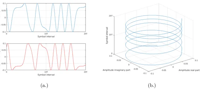
Fig.1.2, (a.) and (b.) illustrate respectively two important aspects of the CPM: the phase continuity between symbols and the constant envelop. The phase continuity yields excellent spectral occupancy. This latter can be shaped by CPM parameters as we would show in sec-tion 1.3.2. The constant envelop, for its part, is desirable when considering nonlinear/fading channels or communication tools generating perturbations (as nonlinearities). For instance in satellite communication, amplifiers on board satellite (TWTA) generate nonlinearities when reaching the saturation point. This effect occurs as well for unmanned aerial vehicle (UAV) communications. Then to prevent this unwanted effect, amplifiers are not used at their maximal power. However transmitted carrier with constant power (as CPM) are insensitive to nonlinear distortions which permits to push amplifiers at their maximal output power. For its numerous qualities, CPM are used in various contexts as in satellite communications [SG13], deep space communications [Sim05], Bluetooh data transmission [Lam+03], aero-nautical telemetry systems [Geo00], automatic identification system (AIS) [Sco+10], GSM mobile communications [MPFBH92], tactical communications [CFC10], machine to machine communications [DL12] and optical communications [Det11].
(a.) (b.)
1.3.2 Effects of some parameters
1.3.2.1 Modulation index h
The modulation index h is usually chosen as a rational number and smaller than one. In the literature, h is frequently written as the ratio between two relatively prime numbers P and Q (such as h = P/Q) where Q is associated to the cardinality of the finite set of phases taken by the CPM scheme in Rimodi’s representation. If irrational modulation index is assumed, the set of phases becomes infinite. Such schemes are avoided here because of the high complexity induced by their associated receivers.
1.3.2.2 CPM memory L
The CPM memory L is the number of previous symbols required to determine the signal waveform of the current symbol. If L is exactly equal to one, the CPM is called full response and when L is strictly greater than one it is called partial response. The CPM memory specifies also the support of the frequency pulse (see Table 1.1). Large L generally leads to complex receivers.
1.3.2.3 The frequency pulse g(u)
As presented in Fig.1.1 (a.) and Table 1.1 the frequency pulse g(u) determines the shape of the CPM (rectangular REC, raise cosine RC, gaussian GMSK, mixture of rectangular and raise cosine Weighted Average CPM...). Its primitive is the phase response q(t), continuous over [0, LT ]. This latter criterium keeps the phase of the CPM signal continuous.
1.3.2.4 Influences of h, L and g(u) on the CPM scheme
h, L and g(u) can be tuned to shape the CPM bandwidth occupancy. It appears that small
values result in CPM signals with large bandwidth occupancy. L impacts also the CPM bandwidth, it seems that large values of L lead to small bandwidth occupancy (but in a lower proportion than h) and reduce the side lobes sizes. Those effects are illustrated Fig.1.3 (a.) for the impact of the modulation index and (b.) for the impact of the CPM memory. However a greater complexity and a worse symbol-error-rate (SER) are the downside of having large
L and small h respectively. Indeed the complexity of the receiver increases exponentially
with L and the SER are impaired when associated with small h (see Fig.1.4 (b.)). g(u), for its part, can modify the main lobe width and the side lobes size according to the chosen shape (RC, REC, gaussian...). Impacts of various frequency pulse shapes on the PSD are displayed Fig.1.4 (b.). It appears that the REC has the narrowest main lobe and RC the lowest out-of-band power.
(a.) (b.)
Figure 1.3: RC (a.) quaternary L = 3 (b.) binary h = 0.5
1.4
Trellis Representation
A trellis is a state diagram. It visually characterizes a set of states linked to each other by connection called transitions. The aim of this section is to present the original states and transitions of the CPM scheme trellis representation [ARS81a],[ARS81b]. Those latter can be identified by decomposing the information-carrying phase Ξ. Then ∀ t ∈ [kT, kT + T [,
0 1 2 3 4 5 6 7 8 9 Eb/N0 dB 10-6 10-5 10-4 10-3 10-2 10-1 100
Symbol Error Rate (SER)
h=0.25 h=0.5 h=0.75
(a.) (b.)
Figure 1.4: (a.) PSD of various CPM M = 2, h = 0.5 (b.) GSMK BTs= 0.5, M = 2, L = 2
Ξ(t, ak 0) is rewritten as follows: Ξ(t, ak0) = 2πh Pk n=0 anq(t − nT ) = 2πhakq(t − kT ) + 2πh k−1 P n=k−L+1 anq(t − nT ) + πh k−L P n=0 an (1.3)
C = 2πhakq(t−kT ) corresponds to the current symbol distribution, D = 2πh
k−1
P
n=k−1−L
anq(t−
nT ) is the contribution of the L − 1 last symbols and ξk= πh
k−L
P
n=0
an is the phase state. By taking the phase state modulo 2π, we can enumerate all its possible values:
• if P is even: ξk∈ {0, πP Q, 2πP Q , ..., π(Q − 1)P Q } • if P is odd: ξk∈ {0, πP Q, 2πP Q , ..., π(2Q − 1)P Q }
A state space emerges from this decomposition. The transition has to depend on C and the state must take into account D and ξ. Consequently, at the kth symbol interval, the encoder state can be completely characterize by the L-tuple:
σk= [ξk, ak−L+1, ..., ak−1] (1.4)
And the transmitted signal in the interval [kT, kT + T [ is completely deduced by the tuple [σk, ak]. By recursion:
σk+1= [ξk+1, ak−L+2, ..., ak]
ξk+1≡ ξk+ πhak−L+1 mod 2π
(1.5)
The original trellis representation has two drawbacks. First the phase trellis is time-varying because of the chosen symmetrical alphabet ({±1, ..., ±(M − 1)} ). It becomes obvious when we draw the phase trajectories of a 1RC (M = 2 and h = 1/2) in Fig.1.5. The phase trajectories in the even intervals (green circle on the figure) do not match with the odd intervals (red circle). Furthermore we notice that the size of the trellis depends on the parity of P so for P even, we obtain Q · ML−1 states and Q · ML transitions and when P is odd this number doubles for both states and transitions. Then, regarding those drawbacks, we conclude this part by saying that the original trellis is not entirely satisfactory.
1.5
Rimoldi’s Decomposition
To address the original trellis’ drawbacks, Rimoldi proposed an astute decomposition of the carrying-phase in [Rim88]. First of all, a time-invariant phase trellis Φ is defined. This latter depends on the traditional phase Ξ plus a corrective term making the new phase trellis time-invariant. Then such a time-invariant phase trellis can be obtained in the following manner ∀ t ∈ [kT, kT + T [,
0 T 2T 3T 4T 5T 6T Symbol interval 0 0.5 1.5 2 Phase
Figure 1.5: Modulo 2π Phase Tree of 1RC
Φ(t, ak0) = Ξ(t, ak0) + π
h(M − 1)t
T (1.6)
πh(M −1)t/T can be absorbed in the signal’s frequency term. For instance if f0is the original
frequency, the new frequency f1 is defined as f1 = f0− h(M − 1)t/2T . To distinguish between both Φ(t, a) and Ξ(t, a), we denote Φ(t, a) the tilted phase. ∀ t ∈ [kT, kT + T [, Φ(t, ak0) is rewritten as follows: Φ(t, ak0) = 2πh k X n=k−L+1 anq(t − nT ) + πh k−L X n=0 an+ πh(M − 1)t T (1.7)
We may introduce the modified data sequence defined by:
un=
an+ (M − 1)
2 (1.8)
In the sequel we denote un ∈ {0, 1, ..., M − 1} the tilted symbol. The astute reader will notice that the modified data digits are just M-ary digits whatever the parity of M . We set
Φ(τ + kT, uk0) = 4πhL−1P n=0 uk−nq(τ + nT ) + 2πh k−L P n=0 un+ πh(M − 1)τ T −2πh(M − 1)L−1P n=0 q(τ + nT ) + (L − 1)(M − 1)πh (1.9) W (τ ) = πh(M − 1) Tτ − 2L−1P n=0 q(τ + nT ) + (L − 1) !
is the data-independent terms. This part is common to all the transmitted continuous-time waveform whatever the value of k. The data dependent (and time independent) term modulo 2π and modulo Q is called the phase state φk= 2πh
k−L
P
n=0
un. This term can take Q possible values whatever the parity of P , which contrasts with the original representation where ξk takes 2Q values for P odd. In the sequel, we would note Q the set of phases taken by φ. Finally at the kthsymbol interval, the encoder state can be completely characterize by the L-tuple:
δ0k= [φk, uk−L+1, ..., uk−1] (1.10)
And the transmitted signal in the interval [kT, kT + T [ is completely deduced by the L-tuple [δk0, uk]. By recursion:
δ0k+1= [φk+1, uk−L+2, ..., uk]
φk+1 ≡ φk+ 2πhuk−L+1 mod 2π
(1.11)
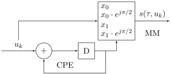
The encoding stage, leading to δk0, is done through a linear continuous phase encoder (CPE) then, a memoryless modulator (MM) mapps δ0k’s symbols with the phase response q(t) (see Fig. 1.6). Those two steps are described in the next section.
Linear Continuous Phase Encoder
Memoryless Modulator
uk δk0
1.5.1 CPM system
Taking into account the tilted phase and the tilted symbols, the signal is redefined as follows:
s(τ, ukk−L+1) = s Es T A(τ )e j4πh L−1 P n=0 uk−nq(τ +nT ) ejφk (1.12)
Where A(τ ) = ejW (τ ) is the Rimoldi’s data independent term.
1.5.1.1 The continuous-phase encoder (CPE)
As pointed out previously, at the kth symbol interval, the CPE updates the L-tuple δ0k using the next symbol uk to generate the next MM input δ0k+1. The CPE can be designed by a shift register thereby, at each time clock, T symbols are moved by one in the shift register (replacing k by k + 1 in δ0k−1) and φk is updated by adding uk−L+1 (1.11). A possible realization of the CPE is proposed in Fig.1.7.
D D ... D D P D
[δ0k, uk]
uk uk−1 uk−2 uk−L+2 uk−L+1
φk
Figure 1.7: Continuous phase modulator.
1.5.1.2 The memoryless modulator (MM)
The memoryless modulator maps the output of the CPE into a set X of ML continuous-time waveforms with finite continuous-time support of length LT . At the kth symbol interval, the subset
ukk−L+1= {uk−L+1, ..., uk} matches xi(τ ) corresponding to the ithsignal ofX = {xi(τ ), i = 0...ML− 1}
xi(τ ) = A(τ ) √ T · e j4πh L−1 P n=0 uk−nq(τ +nT ) , τ ∈ [0, T ), (1.13)
The index i is determined as follows.
i =
L−1
X
n=0
uk−n· ML−1−n (1.14)
It seems that some explanations are needed for the evaluation of index i. Since symbols belong to the M-ary alphabet, they may take M possible value. For partial CPM, the phase trajectory depends on a set of L symbols. Thus X is composed of MLpossible trajectories. To sort each of them in X, we decided to make use of index i. For instance the set ukk−L+1 = {0, ..., 0} corresponds to the first index i = 0 according to (1.14). As well the set ukk−L+1= {1, 0, ..., 0} corresponds to the second index i = 1 and so on. We could equivalently replace index i by its depending set of symbols ukk−L+1 and write xuk
k−L+1 .
We will terminate this section showing a basic example of the Rimoldi’s decomposition for the MSK modulation Fig.1.8. The set of samples is {±1} which corresponds in the tilted domain to the set {0, 1}. The cardinality of the tilted phase’s set is divided by 2 when we compare to the cardinality of original phase’s set , then φ ∈ {0, π/2}.
+ D x0 x0· ejπ/2 x1 x1· ejπ/2 uk s(τ, uk) MM CPE