HAL Id: hal-01657898
https://hal.archives-ouvertes.fr/hal-01657898
Submitted on 7 Dec 2017HAL is a multi-disciplinary open access
archive for the deposit and dissemination of sci-entific research documents, whether they are pub-lished or not. The documents may come from teaching and research institutions in France or abroad, or from public or private research centers.
L’archive ouverte pluridisciplinaire HAL, est destinée au dépôt et à la diffusion de documents scientifiques de niveau recherche, publiés ou non, émanant des établissements d’enseignement et de recherche français ou étrangers, des laboratoires publics ou privés.
Manufacturing and quasi-static bending behavior of
wood-based sandwich structures.
John Susainathan, Florent Eyma, Emmanuel de Luycker, Arthur Cantarel,
Bruno Castanié
To cite this version:
John Susainathan, Florent Eyma, Emmanuel de Luycker, Arthur Cantarel, Bruno Castanié. Manufac-turing and quasi-static bending behavior of wood-based sandwich structures.. Composite Structures, Elsevier, 2017, 182, pp.487-504. �10.1016/j.compstruct.2017.09.034�. �hal-01657898�
To link to this article:
DOI:10.1016/j.compstruct.2017.09.03
URL:
https://doi.org/10.1016/j.compstruct.2017.09.034
This is an author-deposited version published in: http://oatao.univ-toulouse.fr/ Eprints ID:
18480
To cite this version:
Susainathan, John and Eyma, Florent and De Luycker, Emmanuel and
Cantarel, Arthur and Castanier, Bruno Manufacturière and quasi-static
bending behavior of wood-based sandwich structures. ( In Press: 2017)
Composite Structures, vol. 182 (n° 15). pp. 487-504. ISSN 0263-8223
O
pen
A
rchive
T
oulouse
A
rchive
O
uverte (
OATAO
)
OATAO is an open access repository that collects the work of Toulouse researchers and makes it freely available over the web where possible.
Any correspondence concerning this service should be sent to the repository administrator: staff-oatao@listes-diff.inp-toulouse.fr
Manufacturing and quasi-static bending behavior of wood-based
sandwich structures.
John SUSAINATHAN1, Florent EYMA1, Emmanuel DE LUYCKER1, Arthur
CANTAREL1, Bruno CASTANIE1
1
Institut Clément Ader (ICA), Université de Toulouse, CNRS UMR
5312-INSA-ISAE-Mines Albi-UPS, Toulouse, France.
Abstract
The quasi-static behavior of innovative wood based sandwich structures with plywood core and skins made either of aluminum or of fiber reinforced polymer (carbon, glass or flax composite skins) was investigated. The wood based sandwich structures were subjected to three point static bending tests to determine their strength and failure mechanisms. Two different manufacturing processes, namely vacuum bag molding and thermo-compression, were used to manufacture the structures. The influence of some aspects of the different manufacturing processes on the flexural behavior of wood based sandwich structures are discussed. It is shown that manufacturing processes influence strongly the static responses. Failure modes and strengths are investigated during quasi-static bending tests. Bending tests showed that the mechanical characteristics were very high compared to those of a reference sandwich that is currently used for civil aircraft floors. This new kind of structure is environmentally friendly and very cheap, and seems promising for the transportation industry in general.
*
Corresponding author: bruno.castanie@insa-toulouse.fr
Keywords Wood Failure Mechanical testing Sandwich structures
1. Introduction
A sandwich structure is a laminated composite fabricated by attaching two stiff, thin skins to a thick, lightweight core [1]. Their specific properties, such as high stiffness to weight
ratio and high strength to weight ratio for bending, are the major advantages of these structures. Because of their high corrosion resistance, they are also of significant interest for aeronautical or naval structures [2, 3].
Wood exhibits very particular and complex behavior. The tensile resistance and longitudinal elastic modulus (E1) of wood plies are difficult to obtain directly by means of
tensile and/or compression tests. In fact, the material response along the fiber direction is quite different in tension and in compression. In tension, wood exhibits an elastic-brittle behavior whereas, in compression, it shows an elastic-plastic behavior with limited ductility, which causes premature brittle collapse before complete exhaustion of its plastic resource [4]. Furthermore, the ultimate tensile stress is about twice the ultimate compression strength. However, the longitudinal elastic modulus, E11, is practically the same in tension and
compression [5]. Thus, both the technical literature and the codes suggest that a conventional flexural strength should be fixed, which would be equal for tension and compression and obtained by considering an equivalent linear elastic behavior of the whole section up to collapse. Moreover, whether we consider the impact resistance or the stiffness required for floors in the transportation industry (automotive, naval or aeronautic), this type of loading is of particular interest in the present case study.
Regarding the bending response of wood, Brancheriau et al. [6] performed three and four point bending tests on different groups of wood species, such as obeche, okoume, kotibe, amarante, jatoba and ferreol, in order to compare the differences obtained in bending modulus. The three point bending test underestimated the elastic modulus by about 19% in relation to a four point test, due to the fact that indentation and shear effect are neglected in the former test. Hence Costantino [4] carried out three and four point bending with a simply supported scheme, on chestnut wood specimens. They observed that the tensile failure at the bottom and partial compression failure at the top occurred in the central section of the
specimen because of an excess of tensile and compressive stresses respectively. Borega et al. [7] analyzed the bending response of balsa wood of different densities. They concluded that quasi-static bending on low density balsa wood gave the macrofiber and the porous cellulose matrix enough time (strain rates of 10-4/s) to undergo elastic deformation, which minimized local strain energy.
Because wood and epoxy based reinforced skins used in combination here, the influence of curing temperature on the mechanical behavior of wood was studied. As studies related to the influence of temperature on the mechanical behavior of okoume and poplar are scarce in the literature, we considered the equivalent behavior of pear and spruce at high temperature. Among several results on the influence of temperature on the mechanical behavior of wood, Bekhta [8] revealed that the bending strength of spruce wood dried at room temperature (20°C), was 20% and 5% lower than that of wood specimens heated at 100 °C and 150 °C, respectively, and about 33% higher than wood specimens heated at 200 °C. The elastic modulus was lower for wood specimens at room temperature (20 °C) under 95% RH. Finally, the bending strength of spruce wood decreased by 44–50% as the treatment temperature was raised from 100 to 200 °C, whereas temperature had no effect on the modulus of elasticity. However, the impact of heating on the elastic modulus is greater than the impact of moisture content. Gunduz et al. [9] report that each increase in hygroscopic moisture, for a given temperature, causes a decrease of the elastic modulus and modulus of rupture up to the Fiber Saturation Point [9, 10]. Passard et al. [11] report that the elastic modulus determined at 120 °C is quite homogeneous for the same species and the same direction. It is about twice as high in the radial direction as in the tangential one for species such as spruce and oak, and much higher for oak than for spruce. The fall in bending strength and compression strength for pear and spruce wood increases as the heat treatment temperature is raised from 130 to 200 °C [9, 10]. Yildiz et al. [10] claimed an increase in the
elastic modulus of pear wood heated at 160 °C for 2 hours due to wood moisture decrease. The modulus of rupture of Douglas fir plywood decreased by 44–50% as the heat treatment temperature was raised from 50 °C to 200 °C [12].
It is expected that temperature level and moisture content act as a means of activation of the viscoelastic properties. In general, increasing the heat treatment temperature of wood results in an initial increase in strength parameters such as bending and compressive strength until a certain temperature is reached (e.g. 100 °C for spruce ) followed by decrease in strength for the range from 100 °C to 200 °C due to a reduction in the moisture content of the wood. A reduction in relative humidity also causes a slight increase in bending strength parameters. Based on the above results, the reduction in various parameters, such as elastic moduli, and failure strengths, with increasing curing temperature may be explained by the degradation of wood polymers and hemicelluloses [9-12]. Higher temperature and longer duration of curing cycle result in irreversible deterioration such as a permanent decrease in elastic modulus and compressive strength [12, 13]. In summary, when the curing temperature is higher (up to 160°C) and/ the curing cycle is longer, possible strength and stiffness reduction of plywood (around 10 – 15%) may occur. In this study, we used high temperature (between 125°C and 180°C) and pressure environments in both the vacuum molding and the thermo-compression process for better curing of prepregs and efficient bonding between skins and core. Such a high temperature might have had significant influence on the mechanical behavior of the wood.
Very few applications of wood based sandwich structures are found in automotive [3, 14] or in naval structures [15]. In this work, the objective is to create a green, cheap, efficient material for the transportation industry. The reference material will be a sandwich, made of Nomex honeycomb and carbon skins, used in the floors of aircraft cargo bays. Considering the results mentioned above, plywood was chosen here as the core material for wood based
eco-structures intended for applications in the transportation sector and the wooden sandwich structures developed in the laboratory were compared with reference materials currently used for cargo bay floors. Then, quasi-static three and four point bending tests were conducted in order to analyze the flexural response of longitudinal and transverse samples of the nine different wood based sandwich structures considered. The four point bending test also enabled the bending stiffness of the plywood structure to be evaluated without neglecting deflection due to shear. For each material, two measurement configurations were used (longitudinal and transverse) in order to take the wood ply orientations into account. The force–displacement response and failure modes of wood based sandwich structures under quasi-static bending will be compared and described on the basis of a bending scenario deduced from the images of damaged samples.
2. Materials and manufacturing methods
In this work, sandwich materials with plywood core and composite skins were manufactured in order to compare their properties with those of reference materials: a sandwich with carbon composite skins and Nomex (made of aramid) Honeycomb core used for aeronautical floors (reference materials supplied by AIRBUS). Different skin materials were tested: glass, carbon and finally flax fiber composites in order to have a quasi-all green sandwich. There are various methods for manufacturing sandwich structures. A review of the literature and experience gained in the laboratory led us to compare vacuum bag molding with prepreg, Liquid Resin Infusion, and thermo-compression with prepreg in order to find the most suitable method. Some trials (not reported here) revealed that the liquid infusion process needed further development and so it was not used to make the test materials. Thus the work focused on vacuum bag molding and thermo-compression of prepregs.
2.1. Material selection
2.1.1. Plywood Cores
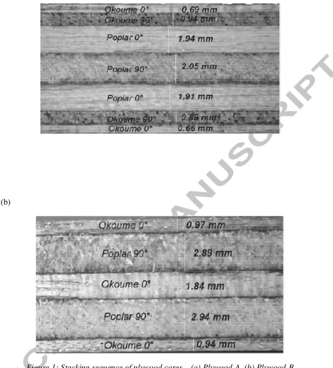
Sandwich cores are generally made of a thick, lightweight material that provides compression resistance to separate the skins and give quadratic momentum. Plywood is made of thin layers of wood bonded together with an adhesive. Each layer of wood, or ply, is usually oriented with its grain running at right angles to that of the adjacent layers in order to reduce shrinkage and improve the strength and stiffness of the finished product, which has comparable strength in both directions. Two plywood structures with the same thickness were chosen as core materials and were named plywood-A and plywood-B. Both plywood structures were made up of plies obtained from poplar and okoume that were bonded together using Melamine Urea Formaldehyde (MUF) glue. The stacking sequences and thicknesses of plywoods A and B are shown in Fig. 1a and b. For plywood A, the bending stiffness of the core is maximized by putting okoume (which is stiffer) at the top and bottom of the plywood. For plywood B, in-plane stiffness is optimized by using three okoume plies in the 0° direction.
2.1.2. Skins
The skin was made from metallic or composite materials. GFRP (Glass Fiber Reinforced Polymer), CFRP (Carbon Fiber Reinforced Polymer) and FFRP (Flax Fiber Reinforced Polymer) offer lower density with higher strength properties than aluminum. Glass fibers are the most used in industry because of their excellent mechanical performance/price ratio and high temperature resistance, but these fibers have a low tensile modulus and high density [16]. Carbon fiber is known for its excellent mechanical and fatigue resistance and very high elastic modulus. It is widely used in aeronautics for its extraordinary mechanical properties and its low density [17, 18]. Flax fibers have good specific properties due to their low density (1.5 versus 2.5 for fiberglass). They are completely renewable and ecologically friendly [19].
i. Aluminum skin
Among the wide choice of aluminum alloys, those of the 1xxx family were chosen for their ductile behavior, which increases the skin resistance to perforation [20-21]. They are pure aluminum (99.3 – 99.9%) with a combination of tiny impurities. Hence aluminum alloy 1xxx was used for the front and rear skin. Finally, the wood based sandwich was manufactured from a core of plywood-A with aluminum skins having a thickness of 0.5 mm (supplied by Allin) as shown in Fig. 2 and Table 1.
ii. Composite skins
The advantages of composite materials over metals are their higher specific stiffness and specific strength, corrosion resistance, ease of manufacturing and the good control that can be achieved over the fiber content. Some mechanical properties of natural and synthetic fibers are recalled in Table 2. Note the lower density of the flax.
Products made with prepreg materials provide a higher and more regular fiber volume fraction than those made by pultrusion or manual stacking. Aero-prepreg, which is suitable for aircraft floor panels, was chosen. It requires a high temperature for curing and a significant drawback was that the implementation temperature for aircraft construction was too high (120 to 180 °C). All prepregs used in this study were bidirectional twill 2/2 reinforcement fabric with thickness of around 0.33mm and all composite skins were made with 3 layers of prepreg at 0°/90°. A sandwich construction requires thin, high-strength prepreg skins bonded to a thicker honeycomb, foam or wood core. A "self-adhesive" prepreg does not require additional adhesive layers, which enables light structures to be produced at reduced fabrication cost. The carbon fiber/epoxy composite prepreg used in the present study had a fiber volume fracton of 46%. This prepreg was supplied by Hexcell (HEXPLY - 913/54% G973 AS40). The detailed ply stacking sequence and thickness of the plywood with its carbon skin are shown in Fig. 3 and Table 3.
Glass fibre is widely used in the marine industry thanks to its low cost, ease of fabrication, low maintenance, corrosion resistance and excellent mechanical performance / cost ratio [24-26]. This study used E-glass/epoxy composite prepreg with 50% of fiber volume fraction. It was supplied by Hexcel (HEXPLY – 1458/50% / 7781 / 1240). The detailed stacking sequence and thickness of plywood with glass skins is shown in Fig. 4 and Table 4.
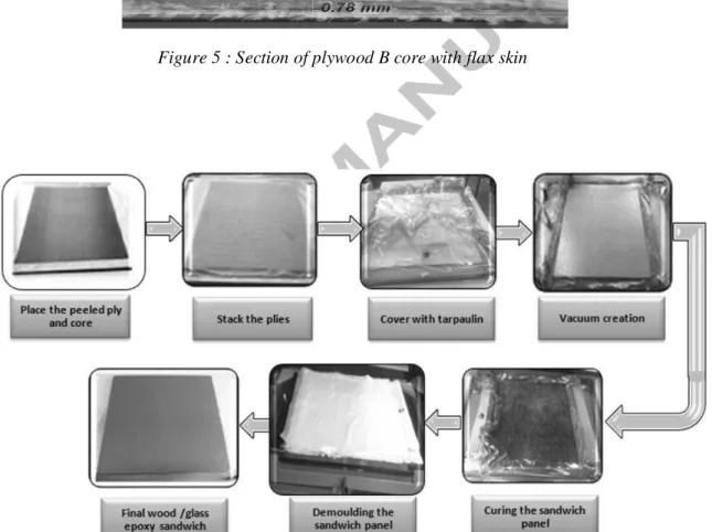
Recently, interest in environmentally friendly materials, such as natural composites, has been growing. Solutions exists that are based on natural fibers instead of synthetic glass and carbon fibers. Their advantages are their biosourced origin, the lower energy necessary for fiber production and lower cost. By using biodegradable polymers as the matrix, we can obtain totally green materials. Natural fibers can compete with synthetic fibers in composites as they have lower density, are healthier in use due to their natural origins, are less abrasive to the processing equipment, and offer good thermal properties and excellent acoustic performance [19, 27]. Among these factors, low density is the key reason why natural fiber composite is attracting interest in the transportation sector. However, the products made from natural fiber composite are still limited to non-structural or sub-structural applications, such as the interiors of cars, because of the high dispersion of their properties. Flax fibers have only 40% of the strength of glass fibers but the same Young's modulus. Their density is only 60% of that of glass fibers, which leads to high specific properties. The flax prepreg used in this work had a 50% fiber volume fraction and was supplied by LINEO (FLAXPREG - BL150/50% 150). The ply sequence and thicknesses of plywood with flax skins are shown in Fig. 5 and Table 5.
2.2. Manufacturing process
2.2.1. Vacuum bag molding
This process consists in stacking plies and core on the mold to make the sandwich and putting a vacuum bag on it. Vacuum bagging is a technique employed to create mechanical pressure on laminate during its cure cycle. This depression has a number of objectives: it removes trapped air between layers and also compacts the fiber layers for efficient force transmission among fiber bundles; it prevents shifting of fiber orientation during the cure; it reduces humidity and, last but not least, the vacuum bagging technique optimizes the fiber ratio in the composite part. All these advantages maximize the physical properties of the sandwich.
With this process, two types of wood core sandwiches were made: one with glass and one with carbon skins. The sandwich was constructed by positioning all the materials on the mold as follows. Three plies of prepreg were peeled and stacked, one by one, at the bottom, the wood core (heated at 90 °C for 1 hour to reduce moisture) was placed in position and three plies of prepreg were stacked on top of it. Finally one ply of drainage fabric was stacked to absorb excess resin. The mold was closed with a sealed covering and the air was evacuated to compact all this together in a vacuum of about 1 bar in order to minimize porosity and have a better fiber ratio. The depression was maintained while the samples were cured in an oven (see Figure 6). Three plates were manufactured for each sandwich material to perform all the mechanical tests.
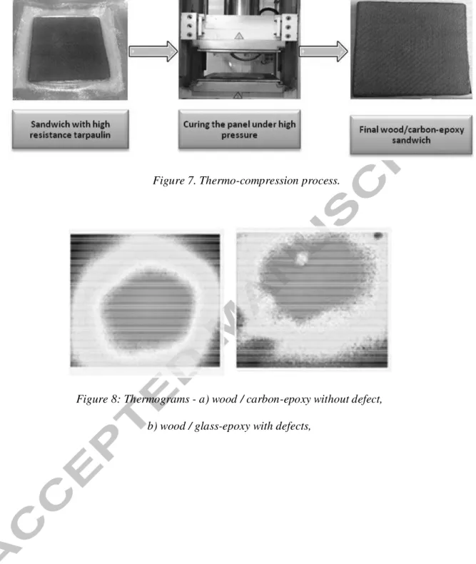
2.2.2. Thermo-compression molding
This process consists in placing the materials of the sandwich (prepreg and core) between two heated platens, then applying pressure to force the materials together, the heat and pressure being maintained until the sandwich has cured (see Figure 7). The pressure and
the temperature imposed are used to reproduce conditions similar to those encountered in an autoclave.
Pre-heated wood that had been cured at 90 °C for 1 hour in order to remove a large proportion of its moisture content was used. For the curing cycle development, the initial focus was to develop a reliable set of cure process parameters, such as temperature, pressure and cycle duration, that satisfied the cure, porosity, fiber volume fraction, and dimensional requirements. The pressure and temperature of the curing cycle was calibrated starting from 1 bar and 90°C. Once the tests had been validated, Panels 500 x 500 mm2 were made under the same conditions but with an equivalent pressure of 4 bars. The time of the curing cycle was chosen according to the prepreg specifications.
2.3. Quality inspection
Several works have shown that thermograms acquired by infra-red thermography (IRT) can be used to highlight and characterize damage or defects in composite materials [28]. In this work, thermal acquisition was carried out on one face of the sample with a FLIR Titanium SC7000 retrofitted camera (InSb sensors, focal plane array of 320x256 pixels, thermal resolution of around 25 mK), some post-processing of derived thermal fields was sometimes necessary to reveal and localize heterogeneities more precisely. The aim of these tests was to ensure that the defects (delamination or debonding for example) identified would not interfere with or influence the behavior of the sandwiches. After detection, other techniques could be used to distinguish the type of defect: more precise non-destructive testing, like ultrasound, or destructive testing. Thermograms of wood based sandwich structures without and with defects are shown in Fig. 8 a and b respectively. In the case of wood based sandwich panels with glass-epoxy prepreg manufactured by vacuum bag molding, a defect was observed on the surfaces near the bottom and top right corners of the
panel, which indicated the presence of air between the wood and the prepreg skin, or a separation or internal cracking due to folds (poor adhesion between the constituents).
It was observed that most of the sandwich panels produced were in good condition without anomalies on the thermograms. Regarding invisible internal defects, a homogeneous temperature was observed on the sandwich panels in infrared thermography analysis, indicating the defect-free nature of the sandwich panels. Finally, the defects were identified through IRT (see Table 6) and the plates without defects were taken to make samples.
2.4. Summary
Suitable and inexpensive techniques were used to make sandwich plates with plywood core (Table7). Infrared thermography, which is capable of showing manufacturing defects in a panel, was used as a non-destructive technique, and allowed us to eliminate all parts with defects. Despite its capability, this method needs more experiments to analyze the type of defect during the manufacturing process. In our case, prepregs were used to make the skins, which gave the skin good mechanical properties despite their high curing temperature (120-180°C) which could cause a loss of mechanical properties of wood and problems of bonding, also with wood. For the technique of vacuum bag molding with prepreg used for making sandwiches with carbon epoxy skin, there was poor adhesion between the two components (wood core and CFRP skin), which resulted in peeling, caused by insufficient pressure being exerted by depression. This was overcome by with the thermo-compression process, which gave good bonding between the plywood core and the skin and, finally, good sandwich panels for this work.
3. Quasi-static bending behavior.
3.1. Experimental setup and analysisQuasi-static bending tests were conducted using a 100 kN load cell on an MTS universal testing machine (Fig. 9). Three and four point bending tests were conducted according to ASTM standard on longitudinal and transverse specimens. Here, the four point bending test was planned in order to include deflection due to shear in the calculation of the bending modulus by correlating load and displacement in three and four point bending. In this study, at least three specimens of each type of material were tested. Initially, the specimens were placed on two roller supports 30 mm in diameter as shown in Fig. 10 a and b, and loaded at a crosshead displacement rate of 5.5 mm/min. The distance between the roller supports (L) was 220 mm. Load and machine displacements were recorded. The deflection was measured with an LVDT sensor located under the sample at the middle, and the tests were filmed in order to identify the different failure mechanisms. The bending tests were continued until fracture occurred. The test matrix for the samples is summarized in Table 8. Then, a quasi-static bending test was carried out under three and four point bending in order to analyze the flexural response of longitudinal and transverse samples of the nine different sandwich structures. For each material, two measurement configurations were used (longitudinal and transverse) in order to take the influence of the plywood stacking sequences into account.
!" # $ % & '
where ț # ț are the deflections produced in 3 and 4 point bending tests, respectively W1 and W2 are the maximum or Failure load in 3 and 4 point bending tests,
respectively
L1 and L2 are the distance between the supports in 3 and 4 point bending tests,
respectively
b and h are the width and thickness of the specimen, respectively. The apparent bending modulus can be calculated using equation 3.
( )" *
The apparent shear modulus can be calculated using equation 4 +, )"$
The orientation of the top and bottom plies of the plywood were considered as the reference to differentiate between longitudinal (L) and transverse (T) samples. Three samples per orientation having dimensions of 270 (L) x 50 (T) x 10 (N) mm3 for plywood-A, plywood-B and each type of sandwich structure with different skin was fabricated as per the European standard NFT54-606. A sandwich structure used for floors in aircraft interiors was also tested for qualitative comparison. It was made of carbon/glass skins with a 10 mm thick Nomex honeycomb core. By cutting floor panels, samples having dimensions of 270 (L) x 22 (T) x 10 (N) mm3 were fabricated according to ASTM C393. The stacking sequence is given in Table 9. The exact materials are unknown. An overview of specimens and tests performed is provided in Table 8.
3.2. Experimental Response and Failure Modes of Plywood Specimens
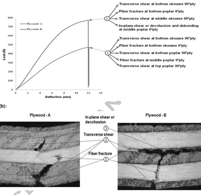
Plywood-A and B:
In the case of longitudinal samples of plywood-A and -B (see Fig. 11 a and b), fiber fracture occurred first at the bottom longitudinal ply (okoume 0°) due to maximum tensile stress, and then propagated as transverse shear through the adjacent transverse ply (okoume 90° for plywood-A, or poplar 90° for plywood-B). Finally, it led to decohesion at the middle transverse ply (poplar 90°) for plywood-A, or fiber fracture at the middle longitudinal ply (okoume 0°) with plywood-B. For transverse samples of plywood-A and B (see Fig. 12 a and b), fiber fracture at the bottom longitudinal ply (okoume 0° with plywood-A, or poplar 0° with plywood-B) and transverse shear at the bottom okoume 90° ply occurred simultaneously and then propagated as transverse shear to the adjacent transverse ply with respect to the type of plywood (poplar 90° with plywood-A, or middle okoume 90° with plywood-B). Finally, it led to transverse shear at the top transverse ply (poplar 90°) with plywood-A, or in-plane shear at the middle transverse ply (okoume 90°) with plywood-B. The only difference in failure modes between plywood-A and plywood-B was the in-plane shear or decohesion at the middle ply (poplar 0° with plywood A, or okoume 90° with plywood B).
As wood has more resistance in the longitudinal direction of its fibers, fiber fracture always occurred at the radial-tangential (RT) plane of longitudinal plies whereas transverse shear always occurred at the radial-longitudinal (RL) plane of transverse plies. Crack propagation always occurred in plywood close to damage caused by peeling, which is the cutting process used to obtain wood plies from the log. This process is known to generate pre-cracks in the radial/longitudinal plane. These peeling cracks may propagate in the same direction or rotate to propagate in the tangent/longitudinal plane because of transverse shear. In summary, the force-displacement histories of plywood structures exhibit a common trend such as linear increase of force as the roller contacts the panel and change in slope, which
indicates crushing through radial compression of cell walls. Then, the drop in peak force occurs due to stiffness reduction caused by fiber fracture, transverse shear or debonding. In the present work the fracture always occurred first at bottom plies due to maximum tensile stress. Fiber fracture and transverse shear were the major failure modes identified in the case of plywood structures under quasi-static bending. However, in the case of plywood structures, there was a peak force drop which indicates a final brittle fracture caused by stiffness reduction.
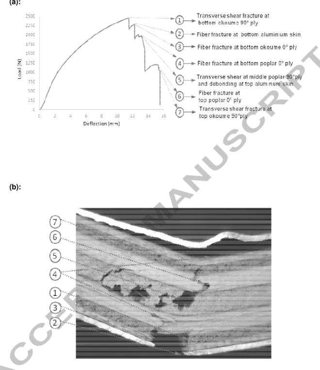
Sandwiches with plywood core and aluminum skin
In the longitudinal case (see Fig. 13), transverse shear at the bottom transverse ply (okoume 90°) occurred first due to maximum tensile stress, and then propagated as decohesion through peeling cracks, which led to fiber fracture at the bottom ply (okoume 0°) and the aluminum skin. Finally, transverse shear occurred at the top okoume 90° ply as shown in Fig. 13. Propagation of in-plane shear through peeling cracks thus occurred only in plywood structures with skin.
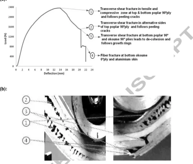
For transverse samples (see Fig. 14), transverse shear and propagation through a peeling crack at the bottom ply (poplar 90°) occurred first and then led simultaneously to fiber fracture at the bottom ply (okoume 0°), transverse shear fracture at the bottom plies, such as poplar and okoume 90°, and bottom aluminum skin fracture. In addition, minor debonding at the top aluminum skin also occurred in the case of transverse samples. Finally, the conclusion was that fiber fracture, transverse shear through peeling cracks, and decohesion and debonding at the top and bottom skin were predominant failure modes under quasi-static bending. It was also noticeable that, because of the plasticity of the aluminum skins, the maximum deflections and strengths were significantly larger than for plywoods alone.
Sandwich with plywood core and carbon skin
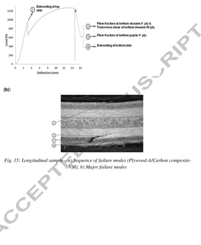
In the case of longitudinal samples of plywood-A with carbon epoxy composite skin produced with the vacuum molding process (see Fig. 15), initially, debonding due to poor adhesion was observed at the top and bottom skins. Transverse shear at the bottom ply (okoume 90°) and fiber fracture at the bottom ply (okoume 0°) simultaneously occurred first due to maximum tensile stress in the bottom plies, and then propagated as fiber fracture at the bottom ply (poplar 0°). Finally, transverse shear occurred at the middle transverse ply (poplar 90° with plywood-A / carbon skins) or fiber fracture at the middle longitudinal ply (okoume 0° with plywood-B / carbon skins).
For a transverse sample, fracture modes and the fracture scenario are shown in Fig. 16. In the case of four point bending on transverse samples of plywood-B with carbon skin, transverse shear at the middle and bottom transverse plies (okoume 90°) simultaneously occurred first and then propagated as decohesion through peeling cracks, which led to fiber fracture at the bottom longitudinal ply (poplar 0° with plywood-B / carbon composite skin) and transverse shear at the bottom transverse ply (okoume 90° with plywood-B / carbon composite skins) as shown in Fig. 16. In this case, a remarkable phenomenon occurred, in which fracture started from the middle, where in-plane stresses were lower, rather than from the top and bottom. This could be explained by prior debonding at the top carbon skin due to poor adhesion caused by the manufacturing process, as compared to a plywood structure with glass skin or also transverse shear stresses. In addition, debonding at the top carbon skin also occurred in both types of samples.
In summary, fiber fracture in longitudinal plies, transverse shear fracture in transverse plies, decohesion through a peeling crack in transverse plies, and debonding at the top and bottom skins were the predominant failure modes under quasi-static bending in the case of plywood structures with carbon composite skin. All of the above failure modes also occur in the case of
plywood structures with glass or flax skin except debonding due to its better adhesion as we shall now observe. The force-displacement plot consists of three main regimes: a linear regime, minor kinking or densification, and unloading. It exhibits a linear trend at lower displacement with the highest peak due to the high stiffness and strength of carbon skin, followed by a peak force drop, which indicates stiffness reduction caused by major failure modes such as debonding between skin and core, fiber fracture and transverse shear.
Sandwiches with plywood core and glass skin
The pictures of longitudinal samples of plywood-A / glass composite skins and their fracture scenarios are shown in Fig. 17. In the case of plywood-A / glass composite skins manufactured by vacuum molding, under four point bending, transverse shear at the middle poplar 90° ply and the top and bottom transverse plies (okoume 90°), and fiber fracture at the bottom ply (okoume 0°) simultaneously occurred first due to maximum tensile stress at the bottom ply, and then propagated as decohesion and in-plane shear in all the transverse plies, which led to fiber fracture at top and bottom longitudinal plies (poplar 0° with plywood-A / glass composite skins) as illustrated in Fig. 17.
The failure modes scenario of transverse samples of plywood-A with glass composite skins manufactured with the vacuum molding process is shown in Fig. 18. In the case of plywood-A / glass composite manufactured by vacuum molding, transverse shear at the top and bottom transverse plies (poplar 90°) occurred first and then propagated as decohesion through peeling cracks, which led to fiber fracture at the middle (poplar 0°) and bottom plies (okoume 0°), and debonding between poplar 90° and poplar 0° plies and at the bottom skin as shown in Fig. 18. Due to better adhesion between glass skins and the core in the thermo-compression process as compared to the plywood structure with carbon skin fabricated by vacuum molding with prepreg, there was no significant debonding at the skins in the case of plywood-B / glass composite skins.
In summary, we found that fiber fracture in longitudinal plies, transverse shear fracture in transverse plies, decohesion through peeling cracks in transverse plies, and debonding at the bottom skin were the predominant failure modes under quasi-static bending in this case.
Sandwiches with plywood core and flax skin
The images of damaged samples of a longitudinal specimen and its fracture scenario are shown in Fig. 19. There is a significant change in slope due to peeling cracks at the top and bottom transverse plies (poplar 90°). In this case of plywood with flax composite skin manufactured by thermo-compression, under four point bending, transverse shear at the bottom ply (Poplar 90°) and fiber fracture at the bottom ply (Okoume 0°) simultaneously occurred first due to maximum tensile stress at the bottom ply, and then propagated as fiber fracture at the middle ply (okoume 0°) (see Fig. 19).
For transverse samples, the images with fractured samples of a transverse specimen and its fracture scenario are shown Fig. 20. In this case, significant change in slope occurs due to a peeling crack at the middle transverse ply (okoume 90°). Transverse shear at the middle transverse ply (okoume 90°) occurred first and then propagated as decohesion through peeling cracks, which led to fiber fracture at the top ply (poplar 0°) and debonding between plies (okoume 90° and poplar 0°).
In summary, because of the better adhesion of flax skins with the core provided by the thermo-compression process, there was no significant debonding at skins as compared to carbon skin manufactured by vacuum molding with prepreg. In both cases, there was a significant change in slope near peak load in both longitudinal and transverse samples, due to peeling cracks at transverse plies (poplar 90° with the longitudinal sample or okoume 90° with the transverse sample). We also found that fiber fracture in longitudinal plies, transverse shear fracture in transverse plies and decohesion through peeling cracks in transverse plies
were predominant failure modes under quasi-static bending in the case of plywood structures with flax composite skin.
Summary.
More generally, it was found that the force-displacement histories of plywood structures with composite skin (Carbon / Glass / Flax epoxy) exhibited certain common trends, such as a linear increase of force as the roller contacted the panel and a small drop in peak force due to a stiffness reduction caused by debonding between the skin and the core. Then, an inelastic plateau occurred, indicating a crushing of cell walls in the plywood core through radial compression. Finally this led to a drop in peak force, which indicated the final rupture caused by fiber fracture and transverse shear.
To sum up, we found that the major fracture modes were fiber fracture, transverse shear, decohesion or longitudinal shear in the case of plywood structures whereas, in the case of plywood structures with either aluminum or composite skins, such as carbon, glass and flax, the predominant fracture modes were fiber fracture, transverse shear, decohesion or longitudinal shear debonding and delamination. Propagation of transverse shear as decohesion or longitudinal shear through peeling cracks occurred only in this case and was due to the bending resistance of the skin. In particular, there was no significant debonding in the case of plywood structures with glass or flax epoxy skin manufactured by thermo-compression with the prepreg process. This was due to adhesion of the skin to the core being better than in the plywood structures with carbon skin fabricated by vacuum molding with the prepreg process.
3.3. Comparative Analysis of Flexural Stiffness and Strength
In this section, the overall behavior of a plywood specimen is compared to that of the reference sandwich, made of carbon skin and Nomex honeycomb core, in terms of flexural stiffness and strength, and also specific values. For each kind of test, the discrepancy was low in terms of stiffness or strength and reached 5 to 10%. So, for simplicity and readability, only a typical response is given and the values provided are average ones.
Plywood -A and -B
As wood has more resistance to traction or compression along the fiber direction, the presence of a greater number of thicker longitudinal (0°) plies with higher modulus was found to cause higher peak load and bending strength in the case of longitudinal samples with plywood-A or in the case of transverse samples with plywood-B. It also caused a change in slope between longitudinal and transverse samples, which led to higher bending stiffness in the longitudinal samples with plywood-A or the transverse samples with plywood-B as shown in Table 10. In contrast, the plywood structure with a greater number of thicker transverse plies, such as transverse samples in the case of plywood-A or longitudinal samples in the case of plywood-B, exhibited good results in terms of shear modulus. The bending modulus found also showed good correlation with the results obtained for three-ply poplar plywood by Vasileiou et al. [29]. Plywood structures also had stiffness and stress comparable to those of the reference sandwich (HC carbon and glass, Fig. 21). However, the reference sandwich clearly had the advantage as far as specific values were concerned, despite its smaller thickness. Regarding the results available in the literature for the flexural response of plywood, it is impossible to predict failure modes with respect to the orientation of the plies in a plywood structure but the originality of the work presented here is related to the accurate identification of the failure mechanisms according to the orientation of the panel (longitudinal or transverse), which will enable numerical models to be improved.
Sandwiches with plywood core and aluminum skins
The force-displacement graph for plywood structures with aluminum skin shows a quasi-linear trend at lower displacements accompanied by non-linearity at higher displacements. The load/displacement history plot (Fig. 22) for the longitudinal and transverse samples of plywood structures with aluminum skin subjected to quasi-static three point bending shows that plywood-A/aluminum skins has higher bending stress and stiffness, and a higher peak load than the reference material (Nomex honeycomb with carbon and glass skin) in the case of a longitudinal sample. However, it has lower specific properties (stiffness and stress) due to its higher density (see Table 10) and also has lower shear modulus than the reference material. It would be possible to lighten the plywood by drilling regular holes and increasing the resistance of the aluminum skin by changing the class of material from 1xxx to 2xxx or others. If this is done, the specific quantities may become closer. The non-linear behavior that can be seen in the force-displacement plot is due to the ductile behavior of aluminum skins. As the isotropic nature of aluminum skin means that there is no significant change in slope between longitudinal and transverse samples, the difference in bending stiffness and shear modulus between them is negligible.
Sandwiches with Plywood Core and Composite Skins
Load/displacement plots for the longitudinal and transverse samples of plywood structures with composite skin made of carbon, glass or flax under quasi-static three point bending are presented in Fig. 23 a and b. Regardless of the manufacturing process considered, the results in Table 12 show that plywood with carbon skin has a higher bending stiffness than all other materials in the case of longitudinal samples, due to the greater stiffness of the carbon skins, and also has specific stiffness and bending stress comparable to those of the reference sandwich. However, the vacuum molding process gave it poor adhesion between the skin and core as compared to the adhesion obtained with the thermo-compression process. In general,
plywood with composite skin, such as carbon, glass or flax skin also has stiffness that is two to three times better than that of the reference sandwich, the specific stiffness and specific shear modulus being comparable to the reference. However, these structures exhibit weak results in terms of shear modulus when compared to the reference material. The results indicate that the reference material seems to yield more stiffness and stress for a very low value of peak load. This difference may be explained by the difference in cross sectional area, which is half that of the other wood based sandwich structures tested. It is interesting to observe, in particular, that plywood with flax skin exhibits specific stiffness that is comparable to that of aramid honeycomb/carbon thanks to the low density of the flax skin. Concerning stress results, plywood with glass skin gives higher bending stress than all other materials in the case of a longitudinal sample, due to the higher strength of its glass skin and the better adhesion between skin and core that comes from the vacuum molding process. Its results in terms of strength and stiffness are comparable with those of the other cases. Specific stresses are clearly still in favor of the reference sandwich but these preliminary results are nevertheless encouraging and optimizations are possible for plywood based sandwich structures. The best compromise solution between stiffness and strength in the flexural response of wood based sandwich panels with these different skins is the plywood (A or B) with glass skin. Its strength is higher and its adhesion better in both kinds of process when compared to carbon skin manufactured by the vacuum molding process.
5. Conclusions
The complete identification of the different modes of damage is an indispensable prelude to the study of new wood-based materials. This should enable them to be precisely modeled and their design and implementation to be optimized.
The manufacturing methods and bending static response of innovative sandwich structures with plywood cores have been studied. It has been shown that the quality of the adhesion between skins and plywood can vary with the manufacturing method (vacuum molding or thermo-compression). Moreover, wood is sensitive to high temperatures and its mechanical properties can be degraded during the manufacturing process. However, bending tests showed that the mechanical characteristics were very high compared to those of a reference sandwich that is currently used for civil aircraft floors. In particular:
- The plywood/carbon composite skins solution is the best in terms of stiffness (almost three times better than the reference aramid honeycomb / carbon and glass material).
- The plywood/glass composite skin solution is the best in terms of resistance (almost twice as good as the reference material).
On the other hand, these solutions will necessarily generate a significant weight penalty as they are around 2 to 3 times the weight of the reference structure (without considering assembly systems such as inserts). Nevertheless, possible optimizations exist to improve the specific resistance of such structures. Moreover, besides being more mechanically efficient and more functional (no need for inserts and possibility of assembling the plates by screwing), these solutions would make significant savings possible as their price is 20 times lower than the current solution. This new kind of structure is environmentally friendly and cheap, and seems promising for the transportation industry in general.
References
[1] ASTM C274-99. ASTM standard terminology of structural sandwich constructions. West Conshohocken, PA: ASTM International; 1999.
[2] Zenkerts D. The handbook of sandwich construction. Engineering Materials Advisory Services Ltd. 1997.
[3] Abrate S, Castanié B, Rajapakse YDS. Dynamic Failure of Composite and Sandwich Structures. Springer 2013.
[4] Giubileo C. Experimental and theoretical analysis of structural behavior of Ancient Timber Structures, Doctoral thesis, 2005.
[5] Giordano G. Tecnica delle Costruzioni in legno (Wooden structure engineering), HOEPLI ed., Milan, Italy, 1989.
[6] Brancheriau L, Bailleres H, Guitard D. Comparison between modulus of elasticity values calculated using 3 and 4 point bending tests on wooden samples, Wood Sci Tech 2002;36:367–383.
[7] Borrega M, Gibson LJ. Mechanics of balsa (Ochroma pyramidale) wood. Mech Mat 2015;84:75–90.
[8] Bekhta P, Niemz P. Effect of High Temperature on Color, Dimensional Stability and Mechanical Properties of Spruce Wood, Holzforschung 2003;57:539–546.
[9] Gunduz G, Aydemir D, Karakas G, The effects of thermal treatment on the mechanical properties of wild Pear (Pyrus elaeagnifolia Pall) wood and changes in physical properties, Mat Design 2009;30:4391–4395.
[10] Yildiz S, Gezerb E, Yildiz U. Mechanical and chemical behavior of Spruce wood modified by heat, Build Env 2006;41:1762–1766.
[11] Passard J, Perré P. Viscoelastic behavior of green wood across the grain. Part I. Thermally activated creep tests up to 120 °C. Ann Forest Sci 2005;62:707–716.
[12] Sinha A, Nairn JA, Gupta R. Thermal degradation of bending strength of plywood and oriented strand board: a kinetics approach, Wood Sci Tech 2009;10: 329-333.
[13] Wood Handbook, Wood as Engineering Materials (2010) Forest Products Laboratory, USA.
[14] http://www.italian.sakura.ne.jp/bad_toys/plywood_monocoque/
[15] Cantwell W, Dirat C, Davies P. A comparative study of thermomechanical properties of sandwich materials for nautical construction, SAMPE J. 1994;30(4):45-51.
[16] Gay D. Composite materials, Design and Applications, CRC Press 2015.
[17] Kassapoglou C. Design and Analysis of Composite Structures. Wiley 2010.
[18] Castanié B, Barrau JJ, Jaouen JP. Theoretical and experimental analysis of asymmetric sandwich structures. Comp. Struct. 2002;55(3):295-306.
[19] Baley C. Analysis of the flax fibres tensile behaviour and analysis of the tensile stiffness increase, Comp. A 2002;33(7):939–948.
[20] Kolopp A, Rivallant S, Bouvet C. Experimental Study of Sandwich Structures as Armour against Medium-Velocity Impacts. Int J Imp Eng 2013;61:24-35.
[21] Abdulhamid H, Kolopp A, Bouvet C, Rivallant S. Experimental and numerical study of AA5086-H111 aluminum plates subjected to impact. Int J Imp Eng 2013;51:1-12.
[22] Hexcel composite prepreg - data sheet (HEXPLY - 913/54% G973 AS40 - www.hexcel.com
[23] Lineo Flax prepreg data sheet – LINEOBL150 - www.lineo.eu
[24] Davies P., Mazeas P., Casari P., Sea water aging of glass reinforced composites: shear behaviour and damage modelling. J. Comp Mat 2001;35 (15):1343-1372.
[25] Peret T, Clement A, Freour S, Jacquemin F. Effect of mechanical states on water diffusion based on the free volume theory: Numerical study of polymers and laminates used in marine application. Comp part B 2017;118:54–66.
[26] Mouritz AP, Gellert E, Burchill P, Challis K. Review of advanced composite structures for naval ships and submarines. Comp Struct 2001:53(1):21-42.
[27] E. Sparnins, Mechanical properties of flax fibers and their composite, Licentiate thesis – 2006, Luleå University of Technology, Sweden.
[28] Barus M, Welemane H, Collombet F, Pastor ML, Cantarel A, Crouzeix L, Grunevald YH, Nassiet V. Bonded repair issues for composites: An investigation approach based on infrared thermography, NDT&E Int 2017;85:27-33.
[29] Vasileiou V, Barboutis I, Kamperidou V. Properties of thin 3-ply plywood constructed with tree-of-heaven and Poplar wood; In proceedings of International Conference “Wood Science and Engineering in the Third Millennium” - ICWSE 2011.
Figures.
(b)
Figure 2: Section of plywood-A with aluminum skin
Figure 3 : Section of plywood-A/ carbon skins
Figure 5 : Section of plywood B core with flax skin
Figure 7. Thermo-compression process.
Figure 8: Thermograms - a) wood / carbon-epoxy without defect, b) wood / glass-epoxy with defects,
Figure 9: overview of 3 point bending test device used.
Figure 10: Schematic diagram of static bending for a) 3 and b) 4 point bending tests [NF-T54606].
(a):
(b) :
(a):
(b):
(a):
(b):
(a):
(b):
(a):
(b):
Fig. 15: Longitudinal sample – a) Sequence of failure modes (Plywood-A/Carbon composite-VM), b) Major failure modes
(a):
(b):
Fig. 16: Transverse sample – a) Sequence of failure modes (Plywood B/Carbon composite – TC), b) Major failure modes
(a):
(b):
Fig. 17: Longitudinal sample –a) Sequence of failure modes (PlywoodA/Glass composite -VM), b) Major failure modes
(a):
(b):
Fig. 18: Transverse sample – a) Sequence of failure modes (Plywood-A / Glass composite – VM), b) Major failure modes
(a):
(b):
Fig. 19: Longitudinal sample – a) Sequence of failure modes (Plywood-B / Flax composite – TC), b) Major failure modes
(a):
(b):
Fig. 20: Transverse sample – a) sequence of failure modes (Plywood B / Flax composite – TC), b) Major failure modes
Figure 21: Longitudinal and transverse load – displacement curves of three point bending for plywood structures and the reference honeycomb/carbon and glass
Figure 22: Load – displacement curves of 3 point bending tests for plywood with aluminum skins.
(a):
(b):
Figure 23: Load – displacement curves of three point bending for plywood structures with composite skin, a) Longitudinal, b) Transverse.
Tables
Table 1: Stacking sequence and thickness of plywood-A/aluminum
Fiber Young’s Modulus E (GPa) Tensile strangth (MPa) Ultimate Strain (%) Density Carbon 230 4500 1.8 1.79 Glass 72 3500 5.4 2.49 Flax 70 1300 1.8 1.45
Table 3: Stacking sequence and thickness of plywood-A/Carbon epoxy
Table 4: Stacking sequence and thickness of plywood-A/Glass epoxy
Type Plies Orientation Thickness (mm) P ly w o o d – A / C a rb o n s k in Carbon Twill f abric (0°/90°) 0.28 Carbon 0.28 Carbon 0.28 Okoume 0 0.53 Okoume 90 0.95 Poplar 0 1.94 Poplar 90 2 Poplar 0 1.99 Okoume 90 0.99 Okoume 0 0.58 Carbon Twill f abric (0°/90°) 0.3 Carbon 0.3 Carbon 0.3
Type Plies Orientation Thickness
(mm) P ly w o o d – A / G la ss s ki n Glass Twill f abric (0°/90°) 0.33 Glass 0.33 Glass 0.33 Okoume 0 0.53 Okoume 90 0.99 Poplar 0 1.94 Poplar 90 2 Poplar 0 1.99 Okoume 90 0.99 Okoume 0 0.58 Glass Twill f abric (0°/90°) 0.33 Glass 0.33 Glass 0.33
Table 5: Stacking sequence and thickness of plywood-B/Flax epoxy
Process Curing cycle
conditions Observations Pressure
Vacuum Molding - Prepreg Carbon At 90°C for 30 min At 125°C for 1hr and cooling in air
Poor adhesion between skin and wood ply causes rupture.
Not pre-heating the wood core results in
delamination between skin and core -1 bar Glass At 160°C for 3h and
cooling in air
Good adhesion between skin and wood core, degradation of wood properties due
to higher temperature Thermo-compression - Prepreg Carbon At 90°C for 30 min At 125°C for 1hr and cooling in air
Smooth surface, the skins are glued to the core very well
4 bar Glass At 160°C for 3h Carbonization of resin on the sides of
plates, but the skins are glued well
Flax At 120°C for 1h Debonding of the skins at the edge of the plate
3 layers of epoxy prepreg with - 2x2 twill weave (0°/90°) fabric
Table 8: Test matrix of wood based sandwich structures for quasi-static bending test (3P- 3 Points, 4P-4 Points
Materials
Young’s Modulus (MPa) Bending stress (MPa) Shear modulus (MPa)
Density (kg/m3) Longitudinal Transverse Longitudinal Transverse Longitudinal Transverse Exp. (E) (MPa) Especific (E/ ) (MPa/kg/m3) Exp. (E) (MPa) Especific (E/ ) (MPa/kg/m3) Exp. ( ) (MPa) specific ( / ) (KPa/kg/m3) Exp. ( ) (MPa) specific( / )
(KPa/kg/m3) Exp. (E) Exp. (E) Plywood -A 5780 12.5 3370 7.3 52.5 114.0 37.0 80.2 204 338 461 Plywood - B 4406 10.2 5140 11.9 37.0 85.4 43.4 100.3 345 109 433 HC/carbon and glass 10520 45.2 12600 54.0 54.2 232.2 72.0 308.6 116 84 233
Table 10: Comparison of flexural response between plywood specimens and reference sandwich made of Aramid Honeycomb (HC) with Carbon and Glass composite skins.
Materials
Young’s Modulus (MPa) Bending stress (MPa) Shear modulus (MPa)
Density (kg/m3) Longitudinal Transverse Longitudinal Transverse Longitudinal Transverse
Exp. (E) (MPa) Especific (E/ ) (MPa/kg /m3) Exp.(E) (MPa) Especific (E/ ) (MPa/kg/ m3) Exp. ( ) (MPa) specific ( / ) (KPa/kg /m3) Exp. ( ) (MPa) specific( / ) (KPa/kg/m3 )
Exp. (E) Exp. (E)
Plywood-A/Al 24960 36.8 22960 33.9 75.5 111.4 69.0 101.8 61 66 678 Aramid HC/carbon and glass 10520 45.2 12600 54.0 54.2 232.2 72.0 308.6 116 84 233
Table 11: Comparison of flexural response of sandwiches with aluminum skins with reference sandwich made of aramid honeycomb (HC) with carbon and glass composite skins.
Table 12: Comparison of flexural response of sandwiches with composite skins and reference sandwich made of Aramid Honeycomb HC/Carbon and Glass composite skins. Materials
Young’s Modulus (MPa) Bending stress (MPa) Shear modulus (MPa)
Density (kg/m3) Longitudinal Transverse Longitudinal Transverse Longitudinal Transverse
Exp.(E) (MPa) Especific (E/ ) (MPa/kg /m3) Exp.(E) (MPa) Especific (E/ ) (MPa/kg/ m3) Exp. ( ) (MPa) specific ( / ) (KPa/kg/ m3) Exp. ( ) (MPa) specific( / ) (KPa/kg/ m3)
Exp. (E) Exp. (E)
V a cu u m m o ld in g Plywood - A / Carbon 34900 61.3 33710 59.2 59.4 104.3 44.7 78.5 52 52 569 Plywood - A /Glass 34300 53.7 33090 51.8 107.3 168.0 94.1 147.5 31 23 638 T h e rm o -c o m p re s si o n Plywood - B /Carbon 31290 50.9 33120 53.9 65.2 106.0 83.1 135.3 49 67 614 Plywood - B /Glass 30970 50.4 32160 52.8 63.3 103.2 72.1 118.4 32 27 609 Plywood - B / Flax 26350 54.0 28190 57.7 46.8 95.7 53.3 109.1 12 13 488 Aramid HC/Carbon and Glass 10520 45.2 12600 54.0 54.2 232.2 72.0 308.6 116 84 233

![Figure 10: Schematic diagram of static bending for a) 3 and b) 4 point bending tests [NF- [NF-T54606]](https://thumb-eu.123doks.com/thumbv2/123doknet/12582054.346880/33.892.225.706.147.532/figure-schematic-diagram-static-bending-point-bending-tests.webp)