HAL Id: hal-00562411
https://hal.archives-ouvertes.fr/hal-00562411
Submitted on 4 Dec 2019
HAL is a multi-disciplinary open access
archive for the deposit and dissemination of
sci-entific research documents, whether they are
pub-lished or not. The documents may come from
teaching and research institutions in France or
abroad, or from public or private research centers.
L’archive ouverte pluridisciplinaire HAL, est
destinée au dépôt et à la diffusion de documents
scientifiques de niveau recherche, publiés ou non,
émanant des établissements d’enseignement et de
recherche français ou étrangers, des laboratoires
publics ou privés.
Method for predicting risk of cracking during weld
repair of heat resistant cast steels
Arnaud Duchosal, Frederic Deschaux-Beaume, Cyril Bordreuil, Gilles Fras,
Philippe Lours
To cite this version:
Arnaud Duchosal, Frederic Deschaux-Beaume, Cyril Bordreuil, Gilles Fras, Philippe Lours. Method
for predicting risk of cracking during weld repair of heat resistant cast steels. Science and Technology
of Welding and Joining, Maney Publishing, 2008, 13, pp.126-135. �10.1179/174329308X283839�.
�hal-00562411�
Method for predicting risk of cracking during
weld repair of heat resistant cast steels
A. Duchosal
1, F. Deschaux-Beaume*
1, C. Bordreuil
1, G. Fras
1and P. Lours
2Owing to their low ductility at room temperature, heat resistant cast austenitic stainless steels are
very sensitive to weld cracking. Cracks are formed in brittle zones of the heterogeneous
microstructure constituted by the carbide rich interdendritic spaces. In order to identify the
operating factors affecting the cracking propensity of such steels during welding, a three step
method, based on numerical simulation, is presented. First, the macroscopic temperature and
stress fields are determined by a finite element calculation, considering a homogeneous material.
In a second step, a localisation criterion is defined to identify critical zones, according to the
macroscopic fields determined in the first step. Then, the heterogeneous microstructure of the
cast steel is modelled in a ‘representative cell’, and the thermomechanical history of the critical
zone previously identified is applied as boundary condition, in order to determine the local stress
field. The cracking is then supposed to occur when the maximal principal stress in the
interdendritic zone of the representative cell reaches the cleavage stress of the carbides,
determined using SEM in situ tensile tests. This method is used to predict cracking during
multipass weld repair of bulk samples, under various welding conditions. A comparison is carried
out between experiment and simulation to validate the method.
Keywords: Heat resistant cast steel, Weld cracking, Numerical simulation, Localisation criterion, Cracking criterion
Introduction
Heat resistant cast austenitic stainless steels are currently used for manufacturing large high temperature compo-nents for the petrochemical industry, or bulk hot forming tools, because of their good corrosion and creep resistances.1–5 However, such materials suffer a quasibrittle behaviour at room temperature, making them sensitive to fatigue cracking. The repair of bulk components is achieved by matter removal around the cracks to form a V groove by machining, and then by filling the groove using arc welding with successive bead deposits (multipass welding).6 Unfortunately, the ther-mal stresses generated by the welding process generally produce new cracks around the repaired zone.
The cracking phenomenon during multipass welding of heterogeneous microstructures is generally attributed to embrittlement phenomena, and can be corrected using of adequate welding consumables.7–11However, in the case of heat resistant cast steels, the low ductility is intrinsically due to their characteristic microstructure, resulting from both the manufacturing process and their composition. These materials are prepared by the sand casting technique and are stabilised using an aging
treatment of several hours aty950uC. The high carbon content, associated with carbide forming elements such as Cr, W, Nb, V or Mo, promotes the carbide precipitation. The microstructure consists of large primary dendrites, separated by narrow interdendritic zones containing primary eutectic carbides, formed at the end of solidification.3,12,13 The dendrites contain a fine dispersion of secondary carbides formed during the aging treatment. The significant creep resistance of these steels is mainly related to the extensive carbide precipitation.1,12Primary carbides prevent intergranular sliding at high temperatures, whereas the secondary precipitates, finely distributed within the grains, reduce the dislocation mobility. However, the primary carbides, forming a quasicontinuous network, are also responsible for the very low ductility at room temperature, the elongation to rupture of such steels being as low as 2%. The low ductility at room temperature of heat resistant cast steels gives such alloys very poor weldability.13–16 Cracking occurs during welding and propagates into the interdendritic zone, due to the brittle behaviour of the carbide phases, and to the stress concentration effect induced by the high difference of mechanical and physical properties between austenitic dendrites and the carbide network.
This cracking phenomenon during welding decreases the lifetime of weld repaired components drastically.17 This is why it is important to understand the factors affecting crack nucleation during welding, and to optimise the welding process to prevent cracking.
1Mechanical and Civil Engineering Laboratory, Universite´ de Montpellier 2,
IUT de Nıˆmes, 30907 Nıˆmes, France
2CROMEP, Research Centre on Tools and Processes, Ecole des Mines
d’Albi-Carmaux, 81013 Albi, France
A numerical method for predicting the risk of cracking during weld repair was developed in order to determine which operational parameters could affect the weld quality. The paper starts with a brief description of the materials and the experiments performed to study the crack phenomenon. Next, the methodology chosen to predict the crack nucleation during the process is presented, and each step of the method is detailed. Finally, the numerical results are discussed and com-pared to experimental data.
Experimental
Materials
The base material chosen is a typical heat resistant cast austenitic stainless steel used for manufacturing hot forming tools. Its composition is given in Table 1, and its physical and mechanical properties in Table 2. Note that the elongation to rupture is extremely low in the whole temperature range from room temperature to 500uC.
Two filler metals are used in the study, in the form of coated electrodes with 2?5 mm core diameter. The chemical composition of the filler metals is given in Table 1. They both have an austenitic structure, in order to match the base material. The first one, designated by the commercial reference 2133Mn (Bo¨hler Thyssen), has a composition similar to the base material, with slightly lower C and Ni contents and higher Mn and Nb contents. The second one, designated 6222Mo (Bo¨hler Thyssen), is a nickel based alloy with a chemical composition similar to a 625 alloy. This material is the most common filler metal used for welding Ni based alloys or heat resistant austenitic stainless steels.
The thermal and mechanical characteristics of the filler metals are indicated in Table 3. The yield strength is higher than that of the base metal. The ultimate elongation at room temperature is high for the two filler metals (above 25%) compared to that of the base metal (2%), indicating that the risk of cracking in the fusion zone is very weak.
Welding experiments
Welding test details
The welding samples are bulk 40061606120 mm3 parallelepiped blocks, representative of industrial tools. A 20 mm deep V groove (60u) is machined on the largest side of the specimens, corresponding to a typical preparation before weld repairing a cracked component. An automatic shielded metal arc welding process, allowing the control of both the welding speed and the arc voltage, is used for the filling of the grooves with several welding passes.
The weld repairs are performed on samples with or without preheating to 400uC (Table 4). Before the samples are welded, the welding parameters, i.e. current
intensity, voltage and welding speed, have been opti-mised for the two filler metals, with or without preheating.
After welding, cross-sections of the samples are cut and polished to observe possible cracks using optical microscopy and scanning electron microscopy (SEM).
Results of welding tests
For all the welding conditions, cracks are in each case observed after welding, located in the base metal very close to the interface with the fusion zone (filling zone), and propagate exclusively through the interdendritic zones rich in primary eutectic carbides (Fig. 1). These observations suggest a standard brittle fracture mechan-ism, due to the thermal stresses associated to the welding operation, and to the brittle behaviour of the primary carbides. The cast steel then consists of a rather ductile austenitic matrix, surrounded by a quasicontinuous network rich in brittle carbides. Then, the material cannot accommodate the thermal stresses by plastic flow, and cracking of the primary carbides occurs when the local stress reaches the cleavage stress of carbides.
In situ tensile tests
In order to understand the cracking mechanism occur-ring in the heat resistant cast steel better, in situ tensile tests were carried out at room temperature, using a TS-300P tensile micromachine type, implemented in a Philips XL30 scanning electron microscope. The tensile sample, with a 2 mm62 mm cross-section and 30 mm length, is ground before the test in order to reveal its microstructure.
The tensile test is carried out at a constant displace-ment rate, by controlling the force. The sample is initially loaded steadily up to 800 N (200 MPa). Then, the sample is loaded in successive increments of 50 N, and the microstructure is observed between each increment in order to detect possible new cracks.
The material in its initial state already contains some cracks inside primary carbides, as seen in the micro-graph of Fig. 2a. These cracks remain stable at the beginning of the test, and start to propagate as the axial load reaches 1090 N (270 MPa). From this stress level, the initial cracks propagate, while other cracks form through primary carbides on the whole sample surface (Fig. 2b). The location and the morphology of the cracks formed at room temperature are similar to those observed after welding, which confirms the assumption of a brittle failure mechanism.
Numerical method of crack prediction
General methodology
The cracking phenomenon occurs during the repair by multipass arc welding of bulk components. Previous works have shown that cracking during welding is dependent on various parameters,18,19in particular:
(i) the composition of the base metal and the filler metal
(ii) the initial temperature of the sample (preheating) (iii) the welding layer structure (volume, number and
sequence of weld depositions).
As welding experiments on bulk samples are expensive, numerical simulation is used to determine the welding conditions that reduce the risk of cracking.
Table 1 Chemical composition of heat resistant cast steel (BM) and filler metals, wt-%
Element C Si Mn Ni Cr Mo Nb Fe BM 0?31 1?45 1?11 40 25 – 0?33 Bal. 6222Mo 0?03 0?3 0?8 63 22 9 3?5 ,1 2133Mn 0?15 0?4 2?8 33 21 – 1?2 Bal.
The modelling of all parameters responsible for the cracking during welding is complex, because its occur-rence depends on macroscopic factors (thermal loading and self-clamping effect), and on microscopic factors (heterogeneous microstructure of the cast steel). Owing to the mismatch in mechanical and physical properties, and to the microstructure morphology, the cracking is controlled by complex local mechanisms. So a macro-scopic criterion would not be able to predict the failure. The failure must be analysed at a local scale, taking into account the local stress state induced by the
microstructure heterogeneities. A methodology based on three step calculation is proposed. Its specificity consists in a partial scale change, with a transfer of information from the global to the local scale.
First, thermomechanical modelling of the welding process using a continuous and homogeneous base material is carried out, in order to access the macro-scopic temperature, stress and strain fields.
Next, a localisation criterion is defined to locate, according to the evolution of the macroscopic fields during welding, the critical zone of the weld repaired sample that runs the highest risk of cracking. This consists in post-processing the macroscopic fields
Table 2 Thermal and mechanical properties of base material Temperature, uC Thermal conductivity, W mm21K21 Specific heat, J kg21K21 Yield strength, MPa Ultimate stress, MPa Elongation, % 20 0?0128 500 220 335 2 500 0?018 500 175 300 5 925 0?0262 590 77 140 35
Table 3 Physical and mechanical properties of filler metals at room temperature (Bo¨hler Thyssen data) Density,
kg mm23 Thermalconductivity,W mm21K21 Specificheat,J kg21K21 Yieldstrength,MPa Ultimatestress,MPa Elongation,%
6222Mo 8?4461023 9?8
61023 429 496 814 40
2133Mn 8?061023
1561023
500 380 600 25
a macrograph showing cracking location in base metal very close to fusion zone; b micrograph showing crack path in interdendritic carbide phase
1 Cross-sections of welded samples
a precracked initial state; b multicracking from loading level of 1090 N (270 MPa)
2 Material cracking during in situ tensile test: horizontal loading direction
calculated in the first step in order to prevent the complete scale change, for each point of the welded material, by selecting the zone of localisation.
Third, a heterogeneous elementary cell, modelling a representative element of the material microstructure, is defined and meshed. The thermal and mechanical histories of the critical zone identified in the second step are applied as boundary conditions to the cell boundaries, in order to obtain a local stress field enabling to predict the cracking of the carbide phase.
Step 1: modelling of welding process
The thermal distribution during welding being a quasistationary problem,20–22i.e. the thermal distribu-tion does not change in a local reference associated to the heat source, except near the edges of the welded samples, a two-dimensional modelling in a cross-section of the sample, with a plane strain hypothesis, has been considered. The numerical simulation is performed using the finite element software Sysweld.
The sample geometry is similar to the one chosen for the welding experiments. It consists of a parallelepipedic block of 1606120 mm2
cross-section, with a 20 mm deep V groove in the largest side. The V groove is filled with 53 successive passes to simulate the multipass weld repair process (Fig. 3). The mesh of each pass is activated just before the weld deposit of the corresponding pass.
The thermal loading is modelled by a power distribu-tion, according to a generalisation of the standard Goldak model20,23 q (x,y,z)~q0exp {f x a ! ! ! !!! " #n1 z y b ! ! ! !!! " #n2 z z c ! ! ! !!! " #n3 h i n o (1) This model enables the calibration of the heat source by adjusting the different parameters q0, f, a, b, c, n1, n2and n3 for each pass, according to the geometry of the deposited pass, thermal measurements and macro-graphic observations carried out in a preliminary experiment. The detailed method employed for calibrat-ing the heat source is described in Ref. 23.
Convection and radiation heat fluxes are prescribed as boundary conditions to the sample surfaces.
The thermal properties versus temperature retained for the modelling of base and filler material behaviours are given in Table 5. The 2133Mn filler alloy has a chemical composition rather similar to the base mate-rial, and its thermal properties are also supposed identical to the base metal.
The base material shows a standard thermoelasto-plastic behaviour with kinematic hardening, which is generally considered well suited for cyclic loading. The evolution of the yield stress versus the equivalent plastic strain for different temperatures is given in Fig. 4a. This behaviour is deduced from the results of the isothermal tensile test.
Table 4 Summary of different welding conditions Test no. Filler metal Preheating temperature,uC
1 6222Mo 20
2 6222Mo 400
3 2133Mn 20
4 2133Mn 400
3 Geometry of V groove machined on bulk sample and layer sequence
Table 5 Physical properties of base metal (BM) and filler metals 2133Mn and 6222Mo used for modelling
Temperature,uC 20 500 750 850 900 950 1050 1200 1400 BM and 2133Mn Thermal conductivity, W mm21K21 0?013 0?018 0?022 0?024 0?025 0?026 0?028 0?030 0?031 Specific heat, J kg21K21 500 500 560 570 575 590 600 650 650 Thermal expansion coefficient,61026K21 16?0 16?2 – 17?9 – – 18?7 – –
6222Mo Thermal conductivity, Wmm21K21 0?010 0?021 0?024 0?026 0?026 0?030 0?032 0?034 0?035
Specific heat, J kg21K21 410 510 560 570 580 590 600 – –
Thermal expansion coefficient,61026
K21 13?2 – – 16?1 – – 17?6 – – a base material; b filler materials used for modelling 4 Mechanical properties
The mechanical behaviour of both filler metals is modelled by a thermoelastoplastic law without hard-ening (Fig. 4b).
The numerical modelling enables the determination of the macroscopic temperature, stress and strain fields in the welded component for each stage of the welding operation.
Step 2: localisation criterion
Because local analysis is impossible to perform at each gauss point or node of the welded component, a critical zone must be located, using a criterion based on macroscopic data. The second step of the method consists in locating a representative zone at the most risk of cracking during weld repair carried out according to a given procedure.
In brittle materials, cracking is the result of a cleavage phenomenon, and the rupture criterion is sometimes defined by a critical value of the maximum principal stress. This criterion was employed in particular by Wu¨rker et al.24to evaluate the risk of cracking of cast steels under thermal stresses.
A similar stress criterion is chosen to locate the critical zone of the base metal during welding. The criterion selected here is thus very simple: cracking is supposed to occur at a given point when the maximum principal stress sPmax reaches a critical value, depending on the material ultimate tensile strength. At each time, and in each point of the structure, the ratio between the maximum principal stress and the ultimate tensile strength of the material at the temperature of the considered point sR(T) is calculated and the maximum value of this ratio is considered
D~ Sup t S
sPmax
sRð ÞT
T (2)
The risk of cracking is supposed to be the highest in a zone where D reaches a maximum during welding.
This criterion is convenient for predicting cracking in homogeneous brittle materials, but fails to take into account the effect of structural heterogeneities, which can locally modify the stress state, for instance, by accumulating dislocations in the vicinity of carbides. In the case of heat resistant cast steels, because of the heterogeneity of the microstructure, this criterion is used to locate the critical zone, but it cannot constitute a cracking criterion. The cracking prediction then requires the determination of local stresses in the material microstructure, which constitutes the third step of the method.
Step 3: microstructure modelling and local
stress calculation
Once the macroscopic localisation criterion has allowed identifying the node exposed to the most critical loading, the temperature, the temperature flow and the strain histories are recovered for this node. This history is then introduced as the boundary condition to the edges of an ‘elementary cell’.
The elementary cell corresponds to a model of a representative microstructure element of the material, selected on a micrograph of the base material. The microstructure element selected is treated by image analysis using Matlab software. A threshold, based on contrast difference, allows separating the carbide rich interdendritic zone from the austenitic matrix (Fig. 5). The coordinates of the points corresponding to the limit between the two zones are then deter-mined, and transferred into the preprocessor of the finite element code Sysweld, which is then used to create contours separating the matrix and the inter-dendritic zone and to mesh the microstructure. Note that the interdendritic zone is considered homo-geneous in the chosen model, while it is actually heterogeneous, because it contains mainly eutectic carbides, but also an austenitic matrix among those carbides.
The major phase in the elementary cell, the austenite, which represents y90% of the surface, is supposed to have the same physical and mechanical properties as the cast steel (Table 5 and Fig. 4a). The interdendritic phase is supposed brittle, with physical and mechanical properties corresponding to those of chromium car-bides.25,26
The boundary conditions applied to the cell bound-aries are sketched in Fig. 6. The imposed temperature at each time, on each face of the cell, is given by
T ~T zX gradT (3)
where T is the temperature recorded in the critical node identified using the localisation criterion, and X the length of the cell.
The displacements imposed to the nodes on the upper and right sides of the cell (Fig. 6), are given by
u ~EX (4)
where E is the macroscopic strain tensor on the critical node, identified using the localisation criterion, and X is the length of the cell.
This is a standard formula used in numerical homogenisation.
This last step enables the calculation of the local stress field by numerical simulation, taking into account the microstructural heterogeneities in the critical zone that has been identified with the macroscopic localisation criterion.
Microstructural observations have revealed that cracking occurs exclusively in the interdendritic regions by a brittle fracture mechanism. The cracks are then supposed to occur when the calculated maximal principal stress in the interdendritic zone is higher than the cleavage stress of the carbides.
Determination of cleavage stress
For predicting the cracking of a cast steel component during a welding operation by the three step method, it is necessary to evaluate the cleavage stress of the eutectic carbides.
The method adopted consists of simulating a tensile test in the elementary cell defined in the previous section, to compare the numerical results with those obtained during in situ tensile tests described in the section on ‘In situ tensile tests’. The cleavage stress of the carbides is considered equivalent to the maximal principal stress in the cell (always located in the inter-dendritic zone), when the cell tensile loading is equi-valent to the cracking stress identified by the in situ tensile test.
The numerical simulation of the tensile test on the cell is carried out with imposed displacements. The experimental results of the in situ tensile tests show that the sample starts to crack for a loading of 1090 N, which corresponds to a mean tensile stress of 270 MPa. Thus the stress distribution in the cell is observed at the time step corresponding to a similar mean stress level in the cell. Figure 7 shows the distribution of the maximum principal stress in the cell for this time step (mean tensile stress in the cell of 270 MPa). Note that the principal stress in the interdendritic zones rich in carbides is at a maximum on a triple point zone (junction of three interden-dritic zones). The maximum value of the principal stress is 505 MPa. This stress value is thus supposed to correspond to the critical level of the maximal principal stress in the carbide network, which results in cracking.
Discussion on methodology and
comparison between simulation and
experiment
Validity of localisation criterion
The localisation criterion chosen is derived from a fracture criterion used for brittle homogeneous materi-als. The authors expect from this criterion a prediction of the location of the critical zone during welding, i.e.
6 Localisation of critical node and boundary conditions imposed on edges of reference cell
7 a geometry of ‘elementary cell’ with interdendritic zone in dark and austenitic matrix in light and b maximum principal stress field in cell exposed to mean tensile stress of 270 MPa
the zone suffering the thermomechanical history produ-cing the highest maximal principal stress in the inter-dendritic zone of the elementary cell. In order to verify whether this criterion is appropriate, the authors have monitored the evolution of the location of the critical zone identified by the criterion after the first passes and have introduced the history of the successive critical zone in the cell.
Figure 8 shows the location of the critical zone given by the criterion after the first four passes. Zone 1 corresponds to the critical zone after the first two passes, whereas zone 2 is the critical zone after the third and fourth passes. Note that the displacement of the critical zone indicates an increase in the risk of cracking. Indeed, a new zone becomes critical only when D parameter in this zone, which is supposed to measure the risk of
a after two passes; b after four passes
cracking, becomes higher than in the last critical zone. The risk of cracking increases with the number of deposited passes, and the zone is moving towards the top.
Figure 9 shows the evolution of the maximal principal stress calculated in the interdendritic zone of the cell, subjected to the history of the critical zones 1 and 2. It can clearly be seen that in zone 1, the interdendritic zone of the cell suffers the highest maximal principal stress during the first and second passes, whereas in zone 2, the maximal principal stress becomes higher for the third and fourth passes. This indicates a pretty good validity of the localisation criterion to predict the zone of the highest risk of cracking.
Comparison simulation experiment and
discussion
The authors only present here the results obtained in the case of the repair with the filler metal 6222Mo without preheating. The other results (6222Mo with preheating and 2133Mn with and without preheating) are discussed in the form of a comparative table between experiment and simulation (Table 6).
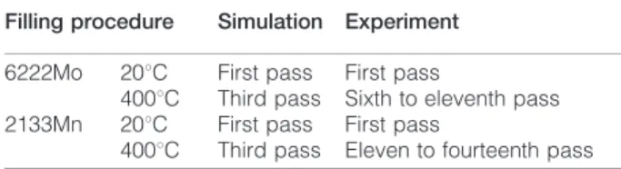
During the welding test without preheating, some cracks were observed at the level of the first welding pass. The numerical simulation calculation of the local cracking risk clearly shows the location of a critical zone, after the first pass, at the bottom of the V groove (Fig. 10a). The loading of the elementary cell with the thermomechanical history of this critical zone then leads to a maximal principal stress after the first pass in the interdendritic zones of 607 MPa, higher than the cracking stress of carbides (505 MPa), thus in complete concordance with the experiment (Fig. 10b). With the 2133Mn filler metal without preheating, the simulation also predicts a cracking after the first filling pass, which conforms to the experimental results (Table 6). On the other hand, with preheating, the simulation overesti-mates the severity of the welding repair operation. When the heat resistant steel is preheated to 400uC, the simulation predicts cracking after the third pass,
whereas the experiment shows that cracking starts from the sixth or the eleventh pass, depending on the filler material. Despite this overestimation of the damaging effect during welding with preheating, the cracking prediction method emphasises the beneficial effect of preheating, since without preheating for both filler materials, the cracking criterion is reached not after the third pass but the first.
The differences observed between simulation and experiment could be for several reasons. First, the thermal and mechanical characteristics of the base and filler materials are generally not identified at high temperatures close to the fusion temperature, so extrapolations of the parameter evolution were neces-sary to model the material behaviour. For the
micro-structure modelling, the morphology of the
representative cell is considerably simplified, because it takes into account two homogeneous phases, the matrix and the interdendritic zone, the latter being actually heterogeneous. Also, the plastic behaviour of the austenitic matrix is considered isotropic, whereas each grain has its own slip planes. Finally, the differences observed can be attributed to the non-detection of the finest of the cracks, due to the limited magnification employed to observe the base material all around the fusion zone. Indeed, these observations fail to detect cracks smaller than 200 mm. Undetected microscopic cracks can thus be formed before the sixth pass, which could then better correspond to the results of the numerical simulation.
Conclusion
A three step method based on numerical simulation was implemented to predict the risk of cracking during the weld repair of heat resistant cast steels. The first step consists of a standard thermomechanical modelling of the welding process, in order to obtain macroscopic temperature, stress and strain fields. In a second step, a critical zone is identified in the welded sample, using a simple maximal principal stress localisation criterion. The third step takes into account the heterogeneous microstructure of the material to calculate local stress fields. A representative microstructure element is mod-elled in an elementary cell, and the thermomechanical history of the critical zone identified in the second step is applied as the boundary condition to the cell bound-aries. This method gives interesting results for predicting cracking during weld repair without preheating, but overestimates the risk of cracking during weld repairs with a 400uC preheating.
Table 6 Summary of location of first cracks according to experiment and simulation
Filling procedure Simulation Experiment 6222Mo 20uC First pass First pass
400uC Third pass Sixth to eleventh pass 2133Mn 20uC First pass First pass
400uC Third pass Eleven to fourteenth pass
9 Evolution of maximal principal stress in interdendritic zone of cell subjected to thermomechanical history of critical zones 1 and 2
References
1. S. K. Bhaumik, R. Rangaraju, M. A. Parameswara, T. A. Bhaskaran, M. A. Venkataswamy, A. C. Raghuram and R. V. Krishnan: Eng. Fail. Anal., 2002, 9, 553–561.
2. L. H. de Almeida, A. F. Ribeiro and I. Le May: Mater. Charact., 2003, 49, 219–229.
3. J. Montagnon, J.Y. Moraux and A. Hocquette: Proc. 3rd European Conf. on ‘Superplastic forming’, Albi, France, July 2004, E´ cole des Mines d’Albi-Carmaux, 117–124.
4. X. Q. Wu, H. M. Jing, Y. G. Zheng, Z. M. Yao, W. Ke and Z. Q. Hu: Mater. Sci. Eng. A, 2000, A293, 252–260.
5. A. K. Ray, S. K. Sinha, Y. N. Tiwari, J. Swaminathan, G. Das and S. Chaudhuri: Eng. Fail. Anal., 2003, 10, 351–362.
10 a location of critical zone after first pass (6222Mo without preheating) and b maximum principal stress in interden-dritic zone of elementary cell in critical zone during deposit of first pass
6. J. L. Desir: Eng. Fail. Anal., 2000, 8, 423–437.
7. K. Nishimoto, K. Saida and H. Okauchi: Sci. Technol. Weld. Join., 2006, 4, 455–461.
8. K. Nishimoto, K. Saida and H. Okauchi, K. Ohta: Sci. Technol. Weld. Join., 2006, 4, 462–470.
9. K. Nishimoto, K. Saida, H. Okauchi and K. Ohta: Sci. Technol. Weld. Join., 2006, 4, 471–479.
10. S. Zenitani, N. Hayakawa, J. Yamamoto, K. Hiraoka, Y. Morikage, T. Kubo, K. Yasuda and K. Amano: Sci. Technol. Weld. Join., 2007, 6, 516–522.
11. N. Yurioka and Y. Horii: Sci. Technol. Weld. Join., 2006, 3, 255– 264.
12. J. Rodriguez, S. Haro, A. Velasco and R. Colas: Mater. Charact., 2000, 45, 25–32.
13. S. Haro, D. Lopez, A. Velasco and T. R. Viramontes: Mater. Chem. Phys., 2000, 66, 90–96.
14. S. Haro, R. Colas, A. Velasco and D. Lopez: Mater. Chem. Phys., 2002, 776, 831–835.
15. S. Haro, C. Ramirez, E. Mendoza, J. Rodriguez and R. Colas: Mater. Charact., 2003, 51, 21–27.
16. T. Branza, A. Duchosal, G. Fras, F. Deschaux-Beaume and P. Lours: J. Mater. Process. Technol., 2004, 155–156, 1673– 1680.
17. T. Branza, A. Martinier, A. Duchosal, F. Deschaux-Beaume, G. Bernhart and P. Lours: Proc. 3rd European Conf. on ‘Superplastic
forming’, Albi, France, July 2004, E´ cole des Mines d’Albi-Carmaux, 133–138.
18. T. Branza, A. Duchosal, C. Bordreuil, F. Deschaux-Beaume, G. Fras and P. Lours: Proc. 4th European Conf. on ‘Superplastic forming’, Manchester, UK, 2005, IOM, 121–126.
19. T. Branza: ‘Weld repair of heat resistant cast steels for superplastic forming dies’, PhD thesis, Universite´ Toulouse III, Toulouse, France, 2005.
20. J. Goldak, A. Chakravarti and M. Bibby: Metall. Trans. B, 1984, 15B, 299–305.
21. P. N. Sabapathy, M. J. Painter and M. Wahab: J. Mater. Process. Technol., 2001, 118, 14–21.
22. M. Wahab, M. J. Painter and M. H. Davies: J. Mater. Process. Technol., 1998, 77, 233–239.
23. A. Duchosal: ‘Repair by multipass welding of heat-resistant cast steels: use of numerical simulation to predict the risk of cracking’, PhD thesis, Universite´ Montpellier II, Montpellier, France, 2006. 24. L. C. Wu¨rker, M. Fackldey, P. R. Sahn and B. G. Thomas:
‘Modelling of casting, welding and advanced solidification processes VIII’, 795–802; 1998, Warrendale, PA, TMS.
25. G. Aliprandi: ‘Mate´riaux re´fractaires et ce´ramiques techniques’; 1989, Paris, Septima.
26. A. Martinier: ‘Life time of refractory steels for SPF tools: tests and simulations’, PhD thesis, Universite´ Toulouse III, Toulouse, France, 2005.