Pépite | Comportement thermo-mécanique de structures géothermiques : modélisations numériques et recommandations
171
0
0
Texte intégral
(2) Thèse de Dina Rammal, Lille 1, 2017. This PhD thesis is dedicated to my beloved parents, and loving sisters. Thank you for all your sacrifices, trust, and support.. © 2017 Tous droits réservés.. lilliad.univ-lille.fr.
(3) Thèse de Dina Rammal, Lille 1, 2017. Acknowledgement The work conducted in this thesis has been carried out at the Laboratory of Civil and GeoEnvironmental Engineering LGCgE at Polytech’Lille, University of Lille 1 under the supervision of Professor Hussein MROUEH and the assistance of Dr. Sébastien BURLON. This PhD thesis has been funded by the Ministry of High and National Education, and Research in France. Foremost, I would like to express my sincere gratitude to my supervisor, Professor Hussein MROUEH for his trust, continuous support, patience, and guidance all along those three years. My gratefulness goes also to Doctor Sébastien BURLON for sharing his knowledge with me, for his precious advices and for the fruitful discussions, all these contributed to improve this work. I would like to thank my PhD committee for accepting to be a part of this achievement by reading, examining, and reporting my work. Thanks to Prof. Anh Minh TANG, Prof. Fabrice EMERIAULT, Dr. Alice DI DONNA, Dr. Lionel DIMONGODIN, and Eng. Julien HABERT. I would like to thank also the Laboratory of Civil and Geo-Environmental Engineering represented by its director Prof. Isam SHAHROUR. My further thanks go to all my friends and colleagues in the LGCgE, in Lille, and in Lebanon. Thanks to your encouragement and motivations. Last but not least, I would like to express my deep gratitude to my father Mohammad, my mother Mariam, and for my sisters Jana, Doha, and Zeina. I would like to thank them for their care, love, support, confidence, and continuous motivation. Without being by my side at every instant, I would not have been here today. Thank you and I love you!. © 2017 Tous droits réservés.. lilliad.univ-lille.fr.
(4) Thèse de Dina Rammal, Lille 1, 2017. Abstract Calorific needs for heating and cooling the buildings account for the majority of their energy demands. To fulfill the thermal needs of constructions without increasing the energy bill and the pollution levels, a solution is to use renewable energy sources that guarantee all these. In this context, geothermal structures represent a promising solution that could satisfy the environmental and the economical necessities at the long term. Geothermal structures act as heat exchanger elements in addition to their major role as bearing structures. Thus, they are subjected to thermal solicitations as well as to mechanical loading. However, their design methods are not clearly defined yet. This work is divided into two main parts that cover the thermal and mechanical design of thermo-active piles and diaphragm walls. Regarding the thermal performance of geothermal structures, the impact of groundwater flow on the heat exchange phenomena between them and the soil is indeed a complex issue. For this reason, in this thesis, two strategies are introduced that are capable to evaluate the allowable exchanged conductive and advective energies. They help to distinguish between different forms of exchanged energies and show how they may vary under cyclic thermal loading. Two and three dimensional hydro-thermal numerical models of geothermal piles and diaphragm walls have been conducted and their thermal performance has been evaluated based on the two presented approaches. On the other hand, regarding the mechanical design, this work covers the issues related to the choice of the thermal solicitation that the designer has to consider for the mechanical design of geothermal structures such as the number of cycles, cyclic thermal amplitude, and influence of. © 2017 Tous droits réservés.. lilliad.univ-lille.fr.
(5) Thèse de Dina Rammal, Lille 1, 2017. the thermal loading order. This work deals with these issues with the aim to facilitate the design of geothermal structures. Adding to this, it considers the factors that may affect their mechanical behaviour. Recommendations are given for the mechanical design of both thermo-active piles and diaphragm walls based on the results obtained from the thermo-mechanical numerical analyses.. © 2017 Tous droits réservés.. lilliad.univ-lille.fr.
(6) Thèse de Dina Rammal, Lille 1, 2017. Résumé Les besoins calorifiques pour le chauffage et le refroidissement des bâtiments représentent la majorité des leurs exigences énergétiques. Pour répondre à ces besoins sans augmenter la facture d'énergie et les niveaux de pollution, une solution est d'utiliser des sources d'énergie renouvelables qui garantissent cela. Dans ce contexte, les structures géothermiques, représentent une solution prometteuse qui pourrait satisfaire les besoins environnementaux et économiques à long terme. Les structures géothermiques agissent comme éléments échangeurs de chaleur en plus de leur rôle majeur en tant que structures porteuses. De ce fait, ils sont soumis à des sollicitations thermiques en plus des charges mécaniques. Cependant, leurs méthodes de dimensionnement ne sont pas encore clairement définies. Ce travail est divisé en deux parties principales qui couvrent le dimensionnement thermique et mécanique des pieux géothermiques et des parois moulées. En ce qui concerne les performances thermiques des structures géothermiques, l'impact du flux d'eau souterraine sur les phénomènes d'échange de chaleur entre les fondations et le sol est en effet un problème complexe. Pour cette raison, dans cette thèse, deux stratégies sont introduites qui sont capables d'évaluer les énergies conductives et advectives échangées admissibles. Ils permettent de distinguer différentes formes d'énergies échangées et montrent comment elles peuvent varier en cas de chargement thermique cyclique. Des modèles numériques couples thermo-hydraulique bidimensionnels et tridimensionnels de pieux géothermiques et de parois moulées ont été réalisés et leur performance thermique a été évaluée en fonction des deux approches présentées.. © 2017 Tous droits réservés.. lilliad.univ-lille.fr.
(7) Thèse de Dina Rammal, Lille 1, 2017. D'autre part, en ce qui concerne le dimensionnement mécanique, ce travail couvre les problèmes liés au choix de la sollicitation thermique que le concepteur doit considérer pour la conception mécanique des structures géothermiques telles que le nombre de cycles, l'amplitude thermique cyclique et l'influence de l'ordre de chargement thermique. Ce travail traite ces problèmes dans le but de faciliter la conception des structures géothermiques. De plus, il considère les facteurs qui peuvent affecter leur comportement mécanique. Des recommandations sont données pour la conception mécanique des pieux géothermiques et des parois moulées basées sur les résultats obtenus à partir des analyses numériques thermo-mécanique.. © 2017 Tous droits réservés.. lilliad.univ-lille.fr.
(8) Thèse de Dina Rammal, Lille 1, 2017. Table of contents Table of contents ...............................................................................................................................i List of figures ..................................................................................................................................vi List of tables .................................................................................................................................. xii Nomenclature ............................................................................................................................... xiii General introduction ......................................................................................................................... 1 CHAPTER 1 : Mechanisms related to the thermal transfer and mechanical behaviour of energy geo-structures ................................................................................................................................... 6 1.1 Introduction ............................................................................................................................ 6 1.2 Overview on energy geo-structures ........................................................................................ 9 1.2.1 Energy piles ..................................................................................................................... 9 1.2.2 Energy diaphragm walls ................................................................................................ 10 1.3 Heat transfer mechanisms .................................................................................................... 11 1.3.1 Heat transfer in soil ....................................................................................................... 11 1.3.2 Heat transfer in energy geo-structures .......................................................................... 14 1.4 Assessment of the exchanged heat between geothermal structures and the surrounding media .......................................................................................................................................... 16 1.4.1 Principles ....................................................................................................................... 16 1.4.2 Factors impacting the heat transfer phenomena between energy-geo structure and soil ................................................................................................................................................ 20. i. © 2017 Tous droits réservés.. lilliad.univ-lille.fr.
(9) Thèse de Dina Rammal, Lille 1, 2017. 1.5 Main issues concerning the thermo-mechanical behaviour of soil and energy geo-structures .................................................................................................................................................... 22 1.5.1 Thermo-mechanical behaviour of saturated soil ........................................................... 22 1.5.2 Thermo-mechanical behaviour of thermo-active piles .................................................. 25 1.5.3 Thermo-mechanical behaviour of thermo-active diaphragm walls ............................... 27 1.6 Main issues and methodology .............................................................................................. 28 CHAPTER 2 : Possible strategies for the evaluation of the thermal exchanged power ................ 31 2.1 Introduction .......................................................................................................................... 31 2.2 Available studies dealing with the assessment of the energy exchange between energy structures and the surrounding media ......................................................................................... 32 2.2.1 Studies carried on energy diaphragm walls ................................................................... 32 2.2.2 Studies carried on energy piles ...................................................................................... 37 2.3 Strategies for the assessment of exchanged thermal power ................................................. 37 2.3.3 Approach 1 .................................................................................................................... 38 Power transferred by conduction.................................................................................................... 38 Power transferred by advection ...................................................................................................... 40 Total transferred power .................................................................................................................. 41 2.3.4 Approach 2 .................................................................................................................... 41 2.4 Conclusion ............................................................................................................................ 44 2.5 Appendix: Calculation of the conductive and advective powers and energies .................... 44 CHAPTER 3 : Assessment of the exchanged energy between geothermal structures and soil .... 48. ii. © 2017 Tous droits réservés.. lilliad.univ-lille.fr.
(10) Thèse de Dina Rammal, Lille 1, 2017. 3.1 Introduction .......................................................................................................................... 48 3.2 Materials’ properties ............................................................................................................ 49 3.3 Two-dimensional energy diaphragm walls .......................................................................... 49 3.3.1 Model geometry and boundary conditions .................................................................... 49 3.3.2 Approach 1 .................................................................................................................... 52 Influence of groundwater flow on the temperature profile ............................................................ 52 Temporal and spatial variation of the allowable exchanged power ............................................... 52 Impact of groundwater flow on the exchanged thermal power ...................................................... 54 Impact of cyclic thermal loading on the allowable exchanged thermal power .............................. 55 Impact of the active length of the diaphragm wall ......................................................................... 59 3.3.3 Approach 2 .................................................................................................................... 60 Distribution of the divergence in the soil ....................................................................................... 61 Evolution of the total exchanged power during the winter season................................................. 62 Cyclic variation of the total exchanged power ............................................................................... 65 3.3.4 Comparison between approach 1 and 2 ......................................................................... 68 3.3.5 Influence of the applied thermal load ............................................................................ 69 3.4 Three dimensional energy diaphragm wall model ............................................................... 74 3.5 Three dimensional energy pile model .................................................................................. 79 3.5.1 Cyclic thermal loading of 3-D energy pile .................................................................... 81 3.5.2 Comparison between 3-D energy diaphragm walls and energy piles ........................... 83 3.6 Conclusion ............................................................................................................................ 84. iii. © 2017 Tous droits réservés.. lilliad.univ-lille.fr.
(11) Thèse de Dina Rammal, Lille 1, 2017. CHAPTER 4 : Thermo-mechanical behaviour of energy piles: Impact of imposed thermal loads ........................................................................................................................................................ 85 4.1 Introduction .......................................................................................................................... 85 4.2 Numerical model .................................................................................................................. 86 4.3 Thermal solicitations under consideration ........................................................................... 89 4.4 Thermal volumetric strain: TS0 ........................................................................................... 91 4.4.1 Pile head displacement .................................................................................................. 91 4.4.2 Normal force distribution .............................................................................................. 92 4.5 Constant pile temperature: TS1 and TS2 ............................................................................. 94 4.5.1 Pile head displacement .................................................................................................. 94 4.5.2 Normal force distribution .............................................................................................. 96. 4.5.3 Comparison between TS0, TS1, and TS2 ..................................................................... 99 4.6 Continuous sinusoidal pile temperature: TS3 .................................................................... 100 4.6.1 Pile head displacement ................................................................................................ 100 4.6.2 Normal force distribution ............................................................................................ 101 4.7 Comparison between the four thermal solicitations ........................................................... 103 4.8 Impact of pile head fixity ................................................................................................... 104 4.8.1 Case TS0R ................................................................................................................... 105 4.8.2 TS1R and TS2R .......................................................................................................... 106 4.8.3 TS3R............................................................................................................................ 109 4.8.4 Comparison between different pile head fixities under variable thermal loads .......... 110 4.9 Influence of soil thermal and thermo-mechanical properties ............................................. 111 iv. © 2017 Tous droits réservés.. lilliad.univ-lille.fr.
(12) Thèse de Dina Rammal, Lille 1, 2017. 4.9.1 Pile head displacement ................................................................................................ 112 4.9.2 Normal force distribution ............................................................................................ 114 4.10 Recommendations for the energy pile design .................................................................. 115 4.11 Conclusion ........................................................................................................................ 116 CHAPTER 5 : Thermo-mechanical behaviour of energy diaphragm walls ................................. 118 5.1 Introduction ........................................................................................................................ 118 5.2 Numerical modelling .......................................................................................................... 119 5.3 Impact of thermal loading type on the mechanical behaviour of energy diaphragm walls 121 5.3.1 Normal forces distribution .......................................................................................... 122 5.3.2 Shear forces ................................................................................................................. 124 5.3.3 Bending moment ......................................................................................................... 125 5.4 Impact of soil thermal properties on the mechanical behaviour of energy diaphragm walls .................................................................................................................................................. 126 5.5 Impact of the soil thermo-mechanical property on the mechanical behaviour of energy diaphragm walls ....................................................................................................................... 127 5.6 Accounting for the soil hardening ...................................................................................... 128 5.7 Comparison between the studied cases .............................................................................. 133 5.8 Recommendations .............................................................................................................. 134 5.9 Conclusion .......................................................................................................................... 135 Conclusion and recommendations for further research ........................................................... 136 References ............................................................................................................................... 141. v. © 2017 Tous droits réservés.. lilliad.univ-lille.fr.
(13) Thèse de Dina Rammal, Lille 1, 2017. List of figures Figure 1. Comparison of worldwide direct-use geothermal energy in TJ/year from 1995, 2000, 2005, 2010, and 2015 (Lund & Boyd, 2016). ……………………………………………………2 Figure 1.1 Installation and carbon dioxide savings in UK by the end of 2015 (GI Energy 2017). 10 Figure 1.2 Heat transfer paths in soil; 1 for particles conduction, 2 for air conduction, 3 for air radiation, 4 for pore air convection, 5 for vapour diffusion, 6 for liquid convection, 7 for liquid conduction (Alrtimi et al. 2016). .................................................................................................... 12 Figure 1.3 Thermal pile heat transfer concepts (a) plan of thermal pile components; (b) temperature differences and component resistances (Loveridge & Powrie 2012). ........................ 16 Figure 1.4 Thermal resistances in the case of energy diaphragm wall (upper part in contact with the excavation on one side). ........................................................................................................... 18 Figure 1.5 Longitudinal distribution of normal and shear forces in a HEP according to thermoelastic model (Arson et al. 2013). .................................................................................................. 25 Figure 1.6 Variation of the thermally induced strains, normal forces, and shear stresses for an energy pile partially restrained at its both ends (Amatya et al. 2012). ........................................... 26 Figure 2.1 Representation of the energy geo-structure and the surrounding soil zones. ............... 39 Figure 2.2. Resistive model for the energy geo-structure and the soil. .......................................... 39 Figure 2.3 Flow chart for the calculation sequence of the conductive and advective powers. ...... 44 Figure 2.4 Illustration of the divergence theorem (https://fr.wikipedia.org/wiki/Flux_électrique). ........................................................................................................................................................ 47. vi. © 2017 Tous droits réservés.. lilliad.univ-lille.fr.
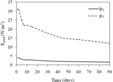
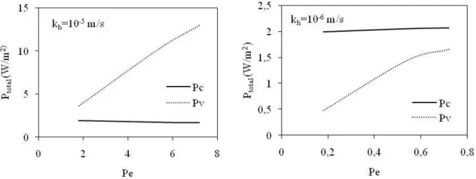
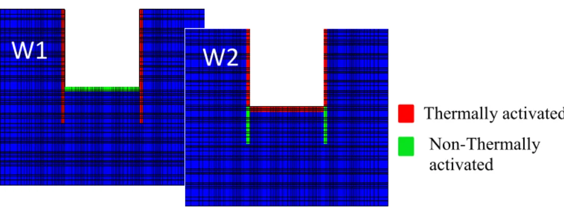
(14) Thèse de Dina Rammal, Lille 1, 2017. Figure 3.1 Geometry of the 2D model representing energy diaphragm walls constituting a metro station. ............................................................................................................................................ 50 Figure 3.2 Temperature profile around the diaphragm walls-kh=10-5 m/s - a) case 1 b) case 2 c) case 3. ............................................................................................................................................. 52 Figure 3.3Variation of the allowable thermal exchanged power along x-direction for the right and left walls (Case 1, kh=10-5 m/s). ..................................................................................................... 53 Figure 3.4 Variation of the total allowable thermal exchanged power during winter season (case 1, kh=10-5 m/s). ............................................................................................................................... 54 Figure 3.5 Variation of Ptotal with Péclet number. .......................................................................... 54 Figure 3.6 Influence of groundwater flow on the exchanged powers Pc and Pv. ........................... 55 Figure 3.7 Temperature variations imposed into the diaphragm wall. ........................................... 56 Figure 3.8 Variation of temperature during the loading cycles. ..................................................... 57 Figure 3.9 Variation of the exchanged power under cyclic loading (kh=10-5 m/s). ....................... 59 Figure 3.10 The modelled diaphragm wall with the two considered configurations. .................... 59 Figure 3.11 Ratio of the total thermal power between the configurations W1 and W2 (kh=10-5 m/s). ................................................................................................................................................ 60 Figure 3.12 Distribution of the total divergence in the domain in the case of pure conduction a) Winter b) Summer. ......................................................................................................................... 61 Figure 3.13 Evolution of the a) advective, b) conductive, and c) total divergences in the soil zones at the end of the winter season (cooling period). ........................................................................... 62 Figure 3.14 Total power a) and advective power b) exchanged by the whole domain during the winter season for the three considered cases with kh=10-5 m/s. ..................................................... 63 Figure 3.15 Evolution of the total, conductive, and advective powers of the whole domain with Péclet number. ................................................................................................................................ 63 vii. © 2017 Tous droits réservés.. lilliad.univ-lille.fr.
(15) Thèse de Dina Rammal, Lille 1, 2017. Figure 3.16 Variation of the power exchanged by the soil surrounding the walls for a) case 1 b) case 2 c) case 3. .............................................................................................................................. 64 Figure 3.17 Total exchanged power a) for the whole domain b) for the zones surrounding the energy walls.................................................................................................................................... 66 Figure 3.18 Exchanged conductive and advective powers, bold lines for conduction, and dotted lines for advection, a) for the whole domain b) for the zones surrounding the diaphragm walls. . 67 Figure 3.19 Energy supplied by the system during the three thermal cycles. ................................ 68 Figure 3.20 Variation of the sinusoidal temperature imposed into the wall. ................................. 69 Figure 3.21 Power exchanged by the whole domain for one year thermal loading under sinusoidal thermal solicitation. ........................................................................................................................ 70 Figure 3.22 Conductive and advective power exchanged by the whole domain. .......................... 71 Figure 3.23 Energy delivered by the energy diaphragm walls. ...................................................... 72 Figure 3.24 Variation of the thermal exchanged power for both types of thermal loading order. . 73 Figure 3.25 Thermal power exchanged in the whole domain and in the zones surrounding the energy walls.................................................................................................................................... 74 Figure 3.26 Geometry of the 3D modeled metro stations with the energy diaphragm walls in green. .............................................................................................................................................. 75 Figure 3.27 Distribution of the total divergence in the domain. .................................................... 76 Figure 3.28 Exchanged power for the whole domain without the thermally activated elements. . 77 Figure 3.29 Exchanged power by the surrounding zones only. ..................................................... 77 Figure 3.30 Distribution of the conductive and advective powers in the surrounding zones. ....... 78 Figure 3.31 Conductive power exchanged by the energy diaphragm walls. .................................. 79 Figure 3.32 Geometry of the three dimensional energy pile model. .............................................. 80. viii. © 2017 Tous droits réservés.. lilliad.univ-lille.fr.
(16) Thèse de Dina Rammal, Lille 1, 2017. Figure 3.33 Distribution of the total divergence in the zones around the pile at the end of the first a) heating phase b) cooling phase. ................................................................................................. 81 Figure 3.34 Power exchanged by the whole domain during three thermal cycles. ........................ 82 Figure 3.35 Power exchanged by the zones surrounding the energy pile only. ............................. 83 Figure 4.1 Model geometry, thermal and mechanical boundary conditions. ................................. 87 Figure 4.2 Load ratio-head displacement variation. ....................................................................... 88 Figure 4.3 Variation of the pile temperature for the three types of thermal solicitations. ............. 90 Figure 4.4 Variation of the thermally induced pile head displacement for a) TS0 b) TS0 with reversed heating and cooling phases. ............................................................................................. 92 Figure 4.5 Axially induced forces at the end of the first and tenth cycles a) TS0 b) TS0 with reversed heating and cooling phases. ............................................................................................. 93 Figure 4.6 Thermally induced axial force a) TS0 b) TS0 with reversed heating and cooling phases. ............................................................................................................................................ 93 Figure 4.7 Variation of the pile head displacement for the cases of constant pile temperature; a) TS1 and TS2 b) TS1 and TS2 with reversed heating and cooling phases. .................................... 95 Figure 4.8 Variation of the axial force at the end of the first and tenth thermal cycles for the case of constant pile temperature a) TS1 b) TS2 c) TS1 with reversed order d) TS2 with reversed order. .............................................................................................................................................. 97 Figure 4.9 Variation of the thermally induced axial force with time a) TS1 b) TS2 c) TS1 with reversed heating and cooling phases d) TS2 with reversed heating and cooling phases. .............. 99 Figure 4.10 Variation of the thermally induced pile head displacement a) TS3 b) TS3 with reversed order of heating and cooling phases. ............................................................................. 101 Figure 4.11 Variation of the axial force at the end of the first and tenth cycles a) TS3 b) TS3 with reversed order of heating and cooling phases. ............................................................................. 102 ix. © 2017 Tous droits réservés.. lilliad.univ-lille.fr.
(17) Thèse de Dina Rammal, Lille 1, 2017. Figure 4.12 Variation of the thermally induced axial force with time a) TS3 b) TS3 with reversed order of heating and cooling phases. ............................................................................................ 102 Figure 4.13 Variation of the axial stress for the fixed pile head a) TS0R b) TS0R with reversed order. ............................................................................................................................................ 106 Figure 4.14 Variation of the thermal axial force with time for the fixed pile head a) TS0R b) TS0R with reversed order. ........................................................................................................... 106 Figure 4.15 Variation of the axial stress for fixed pile head a) TS1R b) TS1R with reversed order c) TS2R d) TS2R with reversed order. ......................................................................................... 108 Figure 4.16 Thermally induced axial force for fixed pile head a) TS1R b) TS1R with reversed order c) TS2R. d) TS2R with reversed order. ...................................................................... 109. Figure 4.17 Variation of the axial stress for fixed pile head a) TS3R b) TS3R with reversed order. ...................................................................................................................................................... 110 Figure 4.18 Thermally induced axial force for fixed pile head a) TS3R b) TS3R with reversed order. ............................................................................................................................................ 110 Figure 4.19 Variation of the pile head displacement for the four cases with respect to the reference case. .............................................................................................................................. 113 Figure 4.20 Vertical displacement (in m) at the end of the tenth cooling phase for a) reference ̊ -1 ̊ -1 case (αT=5x10⁻⁶ C ) b) case a (αT=10x10-6 C ). ........................................................................ 113. Figure 4.21 Variation of the axial normal forces of the four cases and the reference case.......... 115 Figure 5.1 Geometry and the mesh of the model. ........................................................................ 121 Figure 5.2 Different types of the considered thermal loads. ........................................................ 122 Figure 5.3 Variation of the axial normal forces along the diaphragm wall for a) TS2 b) TS2r. .. 123 Figure 5.4 Axial normal force for case TS3. ................................................................................ 124 Figure 5.5 Shear forces along the diaphragm wall for a) TS2 b) TS2r c) TS3. ........................... 125 x. © 2017 Tous droits réservés.. lilliad.univ-lille.fr.
(18) Thèse de Dina Rammal, Lille 1, 2017. Figure 5.6 Bending moment of the diaphragm wall for a) TS2 b) TS2r c) TS3. ......................... 126 Figure 5.7 Variation of the a) normal forces b) shear forces c) bending moment of the diaphragm wall for TS2 with new soil thermal properties. ............................................................................ 127 Figure 5.8 Variation of the structural forces along the diaphragm wall for α=10x10-6 ̊ C-1. ....... 128 Figure 5.9 Variation of the a) principal stress difference and axial strain b) volumetric strain and axial strain. ................................................................................................................................... 129 Figure 5.10 Deformed mesh and deformation contours for Mohr-Coulomb i and ii, and for Hardening soil model iii and iv. ................................................................................................... 130 Figure 5.11 Variation of the normal force N, shear force Q, and bending moment M along the wall at the end of the second excavation phase. ........................................................................... 131 Figure 5.12 Distribution of the plastic zones in the soil for i) Mohr-Coulomb model ii) Hardening soil model. .................................................................................................................................... 131 Figure 5.13 Variation of the normal and shear forces and bending moment for both constitutive laws............................................................................................................................................... 133. xi. © 2017 Tous droits réservés.. lilliad.univ-lille.fr.
(19) Thèse de Dina Rammal, Lille 1, 2017. List of tables Table 2.1 Influence parameters affecting the thermal performance of energy diaphragm walls examined by previous researchers. ................................................................................................. 36 Table 2.2 Thermal resistance values for energy piles (SIA 2005). ................................................ 40 Table 3.1 Hydraulic and thermal parameters of soil and concrete. ................................................ 49 Table 3.2 Temperature imposed in the diaphragm walls (Suryatriyastuti, 2013). ......................... 51 Table 3.3 Hydraulic boundary conditions and flow velocity. ........................................................ 52 Table 4.1 Mechanical parameters of the soil and the pile. ............................................................. 88 Table 4.2 Thermal parameters of the soil and the pile. .................................................................. 89 Table 4.3 Thermal parameters of the four studied cases. ............................................................. 112 Table 5.1 Mechanical parameters of concrete and soil. ............................................................... 119 Table 5.2 Thermal parameters of concrete and soil. .................................................................... 120 Table 5.3 Values of the considered mechanical parameters. ....................................................... 129. xii. © 2017 Tous droits réservés.. lilliad.univ-lille.fr.
(20) Thèse de Dina Rammal, Lille 1, 2017. Nomenclature Greek symbols: αT. thermal expansion coefficient. º C-1. ΔT. temperature gradient. ºC. Δx. center-to-center distance between two adjacent zones. m. ε. deformation. λ. thermal conductivity. ν. Poisson’s coefficient. ρ. density. Kg/m3. σ. stress. Pa. φ. friction angle. º. ψ. dilation angle. º. ω. angular frequency. W/mK. Roman letters: A0. annual amplitude of soil temperature. ºC. B. width of rectangular pile. m. c. cohesion. kPa. cT. specific heat extraction of solid material. J/m3.K. Cv. volumetric heat capacity. J/kgK. Cp. specific heat capacity. J/kgK. d. damping depth. M xiii. © 2017 Tous droits réservés.. lilliad.univ-lille.fr.
(21) Thèse de Dina Rammal, Lille 1, 2017. DT. thermal diffusivity. m2/s. E. elastic modulus. MPa. 𝑟𝑒𝑓. reference triaxial loading stiffness. MPa. 𝑟𝑒𝑓. reference oedometric stiffness. MPa. 𝐸𝑢𝑟. 𝑟𝑒𝑓. reference unloading/reloading stiffness. MPa. E. exchanged energy. kWh. h. heat transfer coefficient. W/m2.K. 𝑗⃗. vector representing heat exchange. 𝑘0𝑛𝑐. coefficient of earth pressure at rest for normal consolidation. kh. hydraulic conductivity. m/s. L. length. m. Lc. characteristic length. m. m. power for stress/level dependency of stiffness used in the hardening soil. 𝐸50. 𝐸𝑜𝑒𝑑. model m. mass flow rate. kg/sec. M. bending moment. kN.m/lm. n. porosity. N. normal force. kN. Pc. conductive power. W/m. Pe. Péclet number. Pv. advective power. W/m2. qT. diffusive heat flux. W/m2. qw. fluid specific discharge. m/s. 𝑞𝑣𝑇. volumetric heat source intensity. W/m3. q. heat flux. W/m2. Q. exchanged heat. W/m. Q. shear frictional force. kN/lm. R. thermal resistance. mK/W. S. degree of saturation. t. time. s. xiv. © 2017 Tous droits réservés.. lilliad.univ-lille.fr.
(22) Thèse de Dina Rammal, Lille 1, 2017. T. temperature. ºC. Tave. annual mean ground temperature. ºC. v. velocity. m/s. w. axial displacement. m. x. distance from the edge of the geothermal structure. m. z. depth. m. Subscripts: adv. advective. c. concrete. cond. conductive. d. dry. d. day. es. energy geostructure. excavation,conv. convection at the excavation side. f. fluid. g. ground. h. hour. in. inlet. mech. due to mechanical load. out. outlet. pcond. conduction of the pipe wall. pconv. convection of the heat carrier fluid. pi. pipe. s. soil. th. due to thermal load. v. volumetric. w. water. y. year. xv. © 2017 Tous droits réservés.. lilliad.univ-lille.fr.
(23) Thèse de Dina Rammal, Lille 1, 2017. General introduction Pollution aggravation induced by large emissions of harmful gases, increases in the price of primary energy sources due to their quick run out caused by excessive demand, and the need to save more spaces; all these factors combined together have led planners and local authorities to encourage the usage of geothermal energy (Lofthouse et al. 2016, P.A. CoE 2010). Energy geostructures that rely on geothermal heat pumps belong to the category of geothermal energy and serve as clean, renewable, and a long-term cost-saving energy source. Following Lund & Boyd (2016), energy savings from the usage of geothermal energy accounted for 352 million barrels of annually oil, and contributed in avoiding 46.1 million tons of carbon and 149.1 million tons of carbon dioxide emissions into the atmosphere. The outcome of the COP 2015 that was held in Paris in December 2015; the Paris agreement has recommended to limit the global temperature rise to well less than 2°C, and has given the grave risk to strive for 1.5°C. To accomplish this goal, the usage of geothermal energy is highly recommended. The concept of geothermal energy is being widely spread in many countries, and this is reflected by the increase in the installed direct-use geothermal capacity and annual utilization by the end of 2014 compared to the data available in 1995 (Lund & Boyd, 2016). Figure 1 represents the evolution of the utilization of direct-use geothermal energy since 1995 till 2015, and it is significant that geothermal heat pumps acquire the highest figures. According to Lund & Boyd 1. © 2017 Tous droits réservés.. lilliad.univ-lille.fr.
(24) Thèse de Dina Rammal, Lille 1, 2017. (2016), the five leading countries in terms of installed capacity of geothermal heat pumps are: USA, China, Sweden, Germany, and France.. Figure 1. Comparison of worldwide direct-use geothermal energy in TJ/year from 1995, 2000, 2005, 2010, and 2015 (Lund & Boyd, 2016).. Geothermal structures present a promising technology in this field. Beside their major role as bearing elements for the constructions, they are gaining attention nowadays due to several reasons. Among these reasons, environmental aspects are prominent with the high need to reduce carbon dioxide emissions all over the world, and consequently alleviate pollution. Moreover, implementing geothermal structures limits the depletion of non-renewable energy sources. Adding to this, the increase of the energy bill required for heating and cooling of the buildings presents a critical issue that requires serious action steps. In this manner, geothermal structures present a promising example for clean and sustainable energy, which are considered as economical solutions at the long-term. Energy piles and recently energy diaphragm walls are being highly installed in several newly developed projects, and thus they require deep studies to improve their design. Despite of the 2. © 2017 Tous droits réservés.. lilliad.univ-lille.fr.
(25) Thèse de Dina Rammal, Lille 1, 2017. wide installation of geothermal structures, the assessment of their sustainability is a tough issue, knowing that the sustainability is an important key factor that allows the evaluation of the thermal and mechanical performance of geothermal structures. The work conducted in this thesis is divided into two main parts. The first part is advocated to study the thermal performance of energy diaphragm walls and energy piles. The impact of the presence of the underground water flow is studied according to two new presented approaches. The second part focuses on the mechanical behaviour of energy piles and diaphragm walls. The influence of the thermal load that must be implemented in these structures at the design stage is studied. Several thermal loading types are considered to give feasible recommendations regarding the most appropriate thermal load to be imposed in geothermal structures. Adding to this, the effect of the thermal and thermo-mechanical parameters of the soil surrounding geothermal structures is evaluated. The presented thesis consists of an introduction, four chapters describing the carried work, and a general conclusion and perspectives. Chapter One is the introduction, it presents an overview on the implementation of energy piles and diaphragm walls around the world. Then, the general mechanisms of heat transfer in the soil and in energy geo-structures are described. Following the factors affecting the heat exchange processes are briefly presented. After that, the mechanical behaviour of the soil and energy geostructures (piles and diaphragm walls) under the impact of thermal loading are presented. These are followed by the main issues that will be dealt with in the presented thesis regarding the energy exchange between energy piles and diaphragm walls, and the surrounding soil, and the mechanical behaviour of energy piles and energy diaphragm walls. Chapter Two is advocated to present in details the two new and simplified approaches that will be used to assess the allowable exchanged energy between energy piles and diaphragm walls, and 3. © 2017 Tous droits réservés.. lilliad.univ-lille.fr.
(26) Thèse de Dina Rammal, Lille 1, 2017. the surrounding soil. Approach 1 is based on the main formulae for conduction and advection, and it calculates the power transferred between the energy geo-structures and the surrounding soil. It is concerned only with the energy exchanged in the soil zones surrounding these structures and are affected by the heat exchange phenomena. Approach 2 based on the energy balance equation tries to evaluate the exchanged power through the assessment of the conductive and advective divergences using the Ostrogradsky theorem. Chapter Three deals with the sustainability of energy piles and diaphragm walls embedded in saturated sandy soil and subjected to cyclic thermal loading. It presents direct numerical applications for the two approaches explained in the preceding chapter using the finite difference code FLAC 3D. Two and three dimensional models are conducted for energy diaphragm walls and energy piles installed in saturated sandy soil. The impact of the presence of underground water flow and thus the advective term is studied as well as the influence of the thermal cyclic loading on the thermal performance of geothermal structures is discussed. Moreover, the effect of the type of the applied thermal load is evaluated. Chapter Four discusses in details the impact of the thermal loads imposed into energy piles on their mechanical behaviour. Different types of thermal loads are considered to cover several climatic conditions and be able to determine the more appropriate thermal load that should be adopted for the design of energy piles. Moreover, the existence of strong super structure-pile connection requires the analysis of the behaviour of restrained pile head, therefore when thermal load is added; the behaviour of restrained piles varies and needs to be studied. Adding to this, the impact of the soil thermal and thermo-mechanical parameters are evaluated to illustrate the importance of assuming real field properties at the design stage. Recommendations are given at the end of this chapter regarding the mechanical design of energy piles.. 4. © 2017 Tous droits réservés.. lilliad.univ-lille.fr.
(27) Thèse de Dina Rammal, Lille 1, 2017. Chapter Five is dedicated to study the impacts of the thermal loading types and the thermal and thermo-mechanical parameters of the soil on the mechanical behaviour of energy diaphragm walls. Finally, it gives some recommendations about the mechanical design of energy diaphragm walls.. 5. © 2017 Tous droits réservés.. lilliad.univ-lille.fr.
(28) Thèse de Dina Rammal, Lille 1, 2017. CHAPTER 1 : Mechanisms related to the thermal transfer and mechanical behaviour of energy geo-structures. 1.1 Introduction Geothermal structures may comprise base slabs, piles, diaphragm walls, and supporting elements for tunnels as linings and anchors. In addition to their traditional role as structural bearing elements, geothermal structures possess a double role as heat exchanger elements that are capable to totally or partially supply other structures with their thermal needs for heating and/or cooling. They are shallow geothermal closed systems, where thin high-density polyethylene plastic pipes are installed as loops within the concrete elements (Brandl 2006, Adam & Markiewicz 2009), these pipes will be connected to the reinforcement bars and a heat carrier fluid flows through them. By virtue of the thermal properties of concrete, the thermal exchange between the energy geo-structures and the surrounding ground is enhanced (Brandl, 2006).. 6. © 2017 Tous droits réservés.. lilliad.univ-lille.fr.
(29) Thèse de Dina Rammal, Lille 1, 2017. Chapter One Although the implementation of geothermal structures is increasing rapidly, but till now there are no specific design codes and methodologies that state the design methods for such structures, except for some recommendations and guidelines regarding their usage in some countries (VDI 2001, SIA 2005, NHBC 2010, GSHP 2012, French Recommendations 2017). A lot of challenges are facing energy geo-structures as the presence of ground water flow near them, thermally induced behaviour of the surrounding soil and its impact on the structures, climatic conditions, presence of near-by existing buildings, and the interaction between heat exchanger elements and their interaction with the super structures. Thus, extensive work should account for all these issues in order to be capable to develop design codes for geothermal structures, with the aim to provide design engineers with simple tools that help them and facilitate the implementation of these structures. Two main issues related to the performance of energy geo-structures need to be studied to better understand their behaviour and facilitate the development of design methods. The first issue is related to the evaluation of the thermal efficiency of geothermal structures. In fact, the key point for assessing the efficiency of geothermal structures is evaluating their sustainability. Sustainability signifies the ability of the production system applied to sustain the production level over long times. Therefore, the sustainability secures the longevity of the resource at a lower production level (Raybach 2002). The thermal performance of energy geostructures is an indicator of their sustainability, thus focusing on the factors that affect their performance is helpful and leads to efficient results. Being surrounded with soil having specific thermal and hydraulic properties, this absolutely affects the thermal exchange between energy geo-structures and the surrounding media (Di Donna & Barla 2016, Di Donna et al. 2016b, Gashti et al. 2015, Maragna & Rachez 2015, Bayandor et al. 2014, Ma & Grabe 2010).. 7. © 2017 Tous droits réservés.. lilliad.univ-lille.fr.
(30) Thèse de Dina Rammal, Lille 1, 2017. Chapter One Assessment of the exchanged heat is indeed a complex issue that needs correct tools for its evaluation and deep analysis to fully understand the heat exchange phenomena including conduction and advection when underground water flow is present. Beside the assessment of the heat exchanged between geothermal structures and the surrounding media, the mechanical behaviour of geothermal structures is the second issue that requires further study. Even though it gains more interest from researchers than the first issue, but till now, taking into account when designing energy geo-structures, the thermal interaction with the soil and its impacts on the mechanical behaviour of the soil and the geothermal structures is not very clear. In this context, the choice of the thermal solicitation (its type, duration, amplitude) to be imposed into the geothermal structures is based on assumptions. Some studies impose a uniform constant temperature neglecting the presence of the U-tubes (Laloui et al. 2006, Suryatriyastuti 2013, Saggu et al. 2015), while others depend on the temperature values measured or obtained at the inlet and outlet tubes (Batini et al. 2015, Gashti et al. 2015, Cecinato & Loveridge 2015, Sterpi et al. 2016). But in fact, with the lack of sufficient in-situ data registration in many regions and climates, then the latter assumption may lead to conservative or may be inefficient results. Thus, defining the thermal solicitation in a proper way could solve such problems and facilitate the design of energy geo-structures. This chapter will present an overview on geothermal structures specifically piles and diaphragm walls, then the heat transfer mechanisms that take place in the soil and in the geothermal structures are discussed, following the approaches that could be used to assess the energy exchanged between geothermal structures and soil are presented. Thereafter, the main issues related to the thermo-mechanical behaviour of soils and energy geo-structures are discussed.. 8. © 2017 Tous droits réservés.. lilliad.univ-lille.fr.
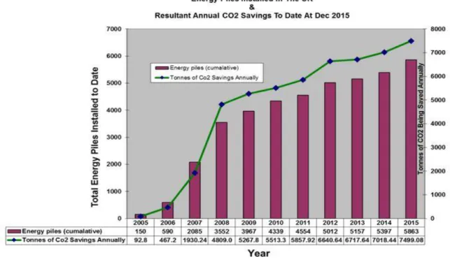
(31) Thèse de Dina Rammal, Lille 1, 2017. Chapter One Finally the main issues considered in this thesis regarding the thermal performance and thermomechanical behaviour of energy piles and diaphragm walls are listed. 1.2 Overview on energy geo-structures 1.2.1 Energy piles Piles are deep foundations formed by a comparatively long and slender columns forced mechanically into the ground. They are used to transfer loads from the super structures to strong and stiff soil with the purpose to decrease the settlement of the super structures (Bazant 1979, Tomlinson & Woodward 2008). Piles foundations, once they are equipped with closed vertical heat exchanger tubes; they will act as heat exchanger elements in addition to their traditional role, thus forming energy piles. Since 1984, energy piles have begun to be used in Austria and Switzerland (Brandl 2006), and their implementation is spreading all around the world. The installation of energy piles is increasing worldwide, but there is lack in the data related to their installation number and the related carbon dioxide savings; Figure 1.1 represents these figures related to the UK experience in this domain.. 9. © 2017 Tous droits réservés.. lilliad.univ-lille.fr.
(32) Thèse de Dina Rammal, Lille 1, 2017. Chapter One. Figure 1.1 Installation and carbon dioxide savings in UK by the end of 2015 (GI Energy 2017).. 1.2.2 Energy diaphragm walls Diaphragm walls are considered as vertical cantilever and they are designed to provide structural support in addition to water tightness. They are widely used in urban excavations for building basements, parking and underground works realized by the cut-and-cover methods, and they are commonly designed as flexible retaining walls. Diaphragm walls started to be equipped with heat exchanger tubes since 1996 (Brandl 2006) where some projects rely on energy diaphragm walls to support excavations or structures and deliver exchanged heat to other buildings. Compared to energy piles, energy diaphragm walls present a great interest through their larger exchange surface area. Mostly, energy diaphragm walls are being used in metro stations as in metro line U2, Vienna (Brandl 2006), Metro line 13 under Shanghai museum (Sun et al. 2013, Xia et al. 2012), Dean Street Station, London (Rui 2014), Tottenham Court Road Station and Moorgate Shaft, London (Di Donna et al. 2016b), Line 10. © 2017 Tous droits réservés.. lilliad.univ-lille.fr.
(33) Thèse de Dina Rammal, Lille 1, 2017. Chapter One 2 of Metro Torino (Cornelio et al. 2016), and Lines 14 and 12 of Paris Metro stations. Even though the spread of energy diaphragm walls remains scarce compared to energy piles, recently, researchers are interested in studying the thermal exchange between energy diaphragm walls and the soil (Di Donna et al. 2016b, Cornelio et al. 2016, Di Donna 2016, Bourne-Webb et al. 2016b), adding to their mechanical behaviour affected by applied thermal loads (Sterpi et al. 2016, Bourne-Webb et al. 2016b, Habert & Burlon 2015). Nevertheless, extensive research is needed to cover all the aspects related to the thermal exchange and mechanical behaviour of energy diaphragm walls as a result of thermally activating them. 1.3 Heat transfer mechanisms Heat transfer takes place when spatial variations of temperature occur. There exist three main mechanisms for heat transfer: conduction, convection, and radiation. 1.3.1 Heat transfer in soil In general, heat transfer in soil is affected by soil thermal properties as thermal conductivity, specific heat capacity, and thermal diffusivity, in addition to the soil hydraulic properties as hydraulic conductivity and flow velocity if groundwater flow of non-static regime exists. These properties depend on the type of soil, its geometry, mineral composition, water content, air content, and porosity. Heat transfer in soils may take place through three main phenomena: conduction, convection and radiation as presented in Figure 1.2.. 11. © 2017 Tous droits réservés.. lilliad.univ-lille.fr.
(34) Thèse de Dina Rammal, Lille 1, 2017. Chapter One. Figure 1.2 Heat transfer paths in soil; 1 for particles conduction, 2 for air conduction, 3 for air radiation, 4 for pore air convection, 5 for vapour diffusion, 6 for liquid convection, 7 for liquid conduction (Alrtimi et al. 2016).. . Conduction: It's the transfer of heat due to direct contact between two bodies derived by temperature difference between them, where these bodies are not moving relative to each other. Conduction is governed by Fourier's Law presented by the following equation:. qcond .T. (1.1). where q is the heat flux, λ is the thermal conductivity coefficient, and T stands for the. temperature. Equation 1.1 represents the first heat conduction law under steady-state conditions, but for non-steady or transient heat conduction we need another law analogous to Fick's second law of diffusion in order to obtain the second law of conduction that is given by the following equation:. C p. T .q t. (1.2). where ρ is the density and Cp is the specific heat capacity. In soils, conduction takes place in the solid phase of the porous media and fluids, which are at rest. Since the soil grains are in contact with each other and the pores in between are. 12. © 2017 Tous droits réservés.. lilliad.univ-lille.fr.
(35) Thèse de Dina Rammal, Lille 1, 2017. Chapter One filled with a mixture of air and water, then heat conduction takes place. Once the soil is more saturated, this means that higher conductive heat transfer occurs. This is related to the dependence of the thermal conductivity on the water content. In addition, it varies with the composition of soil and its compacity, and with the mineralogical components and the chemical properties of the pore water (Brandl, 2006). According to Eslami 2014, the addition of sand to the studied soil samples had a positive impact through increasing their thermal conductivity. As presented by equations 1.1 and 1.2, heat transfer by conduction depends on the thermal properties of the soil, its thermal conductivity, and specific heat capacity. In transient conditions, as Cp starts to play a role, then it is important to note that it increases also with the increase in water content. . Convection: It's the movement of molecules within fluids and is considered as the major mode of heat and mass transfer based on differential movements, due to spatial variations in temperature or chemical concentration. Convection is the sum of advection (molecules are being carried) and diffusion (molecules are being dispersed). Thus, convection is considered as a special form of advection, where advection is a transport mechanism of a substance by a fluid, due to the fluid's bulk motion in a particular direction. In soils, the moving particles which transport heat are water molecules. Therefore, when groundwater flow exists, then one should account for advection that is represented by the following equation: qadv f C f f T. (1.3). 13. © 2017 Tous droits réservés.. lilliad.univ-lille.fr.
(36) Thèse de Dina Rammal, Lille 1, 2017. Chapter One where ρf is the fluid density, Cf is the specific heat capacity of the fluid, vf is the groundwater velocity in liquid phase. Convection in soils can be of two types; forced convection that can be associated with groundwater flow or free convection that can occur due to upward heat flow (Johansen, 1975). To evaluate the relative importance of convective and diffusive heat transport in soils, it is good to introduce Péclet number:. Pe . f C f f . (1.4). Once the Péclet number is greater than 1, then heat exchange is governed by advection, otherwise it is governed by conduction. . Radiation: Radiation is the movement of energy through a medium or vacuum without the movement of molecules. In soils, higher temperature grains radiate more energy and thus energy is transferred by radiation to the lower temperature grains. Generally, in soils, radiation plays almost a negligible role for heat transfer.. According to the soil temperature and its permeability coefficient, one of the three presented mechanisms dominates. Conduction dominates for all ranges of temperature (Sundberg, 1988). However, for temperature above 0°C and in highly permeable soils, forced or/and natural convection will occur and may be significant (Dawson, 2008) 1.3.2 Heat transfer in energy geo-structures Heat transfer in energy geo-structures is a complex phenomenon but can be simplified as presented in Figure 1.3 (for energy piles); it is governed by conduction and convection. Due to the particles’ movement, conduction occurs in the concrete and in the pipe wall. On the other 14. © 2017 Tous droits réservés.. lilliad.univ-lille.fr.
(37) Thèse de Dina Rammal, Lille 1, 2017. Chapter One hand, inside the pipes, heat transfer occurs by convection due to the internal flow of the heat carrier fluid. Convective heat transfer is considered forced since the fluid flow is forced by the heat pump, and it is represented in the following equation: qconv h.T pi T f. . (1.5). where h is the heat transfer coefficient, Tpi and Tf are the temperature of the pipe wall and the fluid respectively. To account for the heat exchange, thermal resistances are to be defined for each heat transfer mechanism taking place. The thermal conductivity is analogous to the Darcy hydraulic conductivity and to electrical conductance, thus thermal resistance can be defined as:. R. T Q. (1.6). where Q may represent either conductive or convective transferred heat in W/m depending on the heat transfer mechanism. For the thermal resistance R as presented in Figure 1.3, it is the sum of the resistances of heat carrier fluid Rpconv, of pipe wall Rpcond, of concrete Rc, and of ground Rg.. 15. © 2017 Tous droits réservés.. lilliad.univ-lille.fr.
(38) Thèse de Dina Rammal, Lille 1, 2017. Chapter One. Figure 1.3 Thermal pile heat transfer concepts (a) plan of thermal pile components; (b) temperature differences and component resistances (Loveridge & Powrie 2012).. Heat transfer in energy geo-structures depends on the material properties of the concrete, pipe, and fluid, and especially on the thermal conductivity (Abuel-Naga et al. 2015). In addition, heat transfer relies on the heat transfer coefficient that depends on the pipe diameter, pipe length, flow velocity, viscosity, density and specific heat capacity, geometric dimensions, and length of heat transfer occurrence (Brandl 2006). 1.4 Assessment of the exchanged heat between geothermal structures and the surrounding media 1.4.1 Principles The thermal exchange between energy geo-structures and the surrounding media differs from one type of structure to the other. In this manner, it is important to note that Figure 1.3 well represents the heat transfer for energy piles, where the pile is totally embedded in soil. For the soil,. 16. © 2017 Tous droits réservés.. lilliad.univ-lille.fr.
(39) Thèse de Dina Rammal, Lille 1, 2017. Chapter One conductive heat transfer always occurs and leads to symmetrical heat exchange, however when water flow is significant then advection takes place too (Chiasson et al. 2000), and then the ground resistivity will be composed of two parts; conductive and advective parts. On the other hand, for energy diaphragm walls; it is not exactly the same. In fact, for energy diaphragm walls, the upper part is in contact with the soil on one side and with the excavation on the other side, thus convection may occur also on the excavation side and depends on the heat transfer coefficient at the excavation side (Figure 1.4). In this figure, Rexcavation,conv stands for the thermal resistance representing the exchange at the excavation side. However, the lower part which is totally embedded in the soil transfers heat with the surrounding in the same way as presented in Figure 1.3.. R=Rg + Rc + Rp,cond + Rp,conv + Rp,cond + Rc + Rp,cond + Rp,conv + Rp,cond +Rc + Rexcavation,conv. 17. © 2017 Tous droits réservés.. lilliad.univ-lille.fr.
(40) Thèse de Dina Rammal, Lille 1, 2017. Chapter One. Figure 1.4 Thermal resistances in the case of energy diaphragm wall (upper part in contact with the excavation on one side).. Generally for a system where there is a convective-diffusive heat transfer, then the energy balance equation is as follows: cT. T q T w c w q w T qvT 0 t. (1.7). where qT is the diffusive heat flux (W/m2), qw is the fluid specific discharge that stands here for the velocity of ground water flow (m/s), qvT is the volumetric heat source intensity (W/m3), and cT is the effective specific heat (J/m3/K). The assessment of the energy exchanged between energy geo-structures and the surrounding media is a complicated issue especially at the design stage where no information about the inlet and outlet heat carrier fluid temperatures would be available. Thus, a more general approach. 18. © 2017 Tous droits réservés.. lilliad.univ-lille.fr.
(41) Thèse de Dina Rammal, Lille 1, 2017. Chapter One should be defined in order to guide the designers, and to avoid conservatism or over-designing of energy geo-structures. Despite of the many applications on energy geo-structures, there is no common approach for the assessment of their thermal performance which depends largely on the thermal transfer between them and the surrounding media. Most of the existing studies estimate the total thermal transfer through Equation 1.8, by taking into account only the thermal and hydraulic properties of the heat carrier fluid (Gao et al. 2008, Bouazza et al. 2013). Qtotal Qin Qout m f .C f .Tin Tout . (1.8). where Qin and Qout (W) are the inlet and outlet heat respectively, mf and Cf are the mass flow rate (kg/s) and the specific heat capacity (J/kg/K) of the heat carrier fluid respectively, and Tin and Tout are the temperatures of the inlet and outlet tubes. Through Equation 1.8, it is difficult to assess precisely the influence of ground conditions on the thermal exchanges: the soil thermal conductivity and its specific heat capacity, the presence of groundwater flow and its permeability. Thus, indeed defining general strategies for evaluating the heat exchange capable to take into account all heat transfer mechanisms is urgently needed to alleviate complexities and facilitate such calculations. Several studies have been conducted on the heat transfer for borehole heat exchangers (Sigfusson & Uihlein, 2015; Diao et al. 2004; Tolooiyan & Hemmingway 2012; Choi et al. 2012), energy piles (Bouazza et al. 2013; Cecinato & Loveridge 2015; Cervera 2013; Ma & Grabe 2010; Zhang et al. 2015; Sedano et al. 2011), and for energy tunnels (Di Donna & Barla, 2016). Energy diaphragm walls present interesting benefits compared to energy piles, they possess a bigger exchange surface with the soil especially in the case of metro stations. They have begun to be studied recently (Di Donna 2016, Cornelio et al. 2016, Di Donna et al. 2016b, Bourne-Webb et. 19. © 2017 Tous droits réservés.. lilliad.univ-lille.fr.
(42) Thèse de Dina Rammal, Lille 1, 2017. Chapter One al. 2016b). All existing studies concerning the energy exchange between energy geo-structures and the surrounding media rely on Equation 1.8 to evaluate the possible exchanged power. 1.4.2 Factors impacting the heat transfer phenomena between energy-geo structure and soil Generally, several factors affect the heat transfer between energy geo-structures and the surrounding media: -. Geometrical configuration of the heat exchanger pipes (Abuel-Naga et al. 2015, Sterpi et al. 2014; Gashti et al. 2014), whether they are single U-tubes, double U-tubes, or Wshaped tubes….. -. Working heat carrier fluid properties and its flow conditions (Abdeen 2014, Sterpi & Angelotti 2013, Xia et al. 2012).. -. Heat transfer at the excavation side in the case of energy diaphragm walls (Bourne-Webb et al. 2016b, Di Donna 2016).. -. Thermal properties of soil and concrete (Abuel-Naga et al. 2015, Abdeen 2014). Higher thermal conductivity boosts conductive heat exchange and thus affects positively the total thermal exchange (Di Donna & Barla 2016; Bourne-Webb et al. 2016b).. -. Groundwater flow properties (Abdeen 2014), its direction and magnitude especially in granular soils have a direct influence on the evolution of temperature around the structural elements and thus on the exchanged energy (Ma & Grabe 2010, Bayandor et al. 2014, Katzenbach et al. 2008, Di Donna & Barla 2016, Di Donna 2016, Maragna & Rachez 2015, Gashti et al. 2015, Zhang et al. 2015), since water flow enhances heat transfer by advection. All studies confirm the positive impact of the presence of water flow on the thermal performance on the system. Concerning the impact of the direction of water flow on the thermal exchange of group of energy piles, Katzenbach et al. 2008 found that 20. © 2017 Tous droits réservés.. lilliad.univ-lille.fr.
(43) Thèse de Dina Rammal, Lille 1, 2017. Chapter One highest expansion of the temperature field occurs towards the direction of the groundwater steam due to stronger convective heat transfer processes compared to sections orthogonal to the groundwater flow. The impact of groundwater flow on the thermal performance of the system depends also on the functioning mode of this system; whether it will be used for heating or cooling only or for both heating and cooling modes. It's noted that heat influx and extraction are necessary for buildings with no or with low flow of ground water, since they provide "active regeneration". In this manner, whenever the water flow exceeds 0.05 m/day, then heat storage requires protecting hydraulic screen (Van Meurs, 1986). In addition heat injection and extraction ensure that energy balance will occur during the whole year, also this confirms that individual systems don't short-circuit, that the natural recovery process can still occur at long term and prevents possible impacts on other nearby installations (Bouazza et al. 2011, Brandl 2006). However, if only cooling or heating is required then high soil permeability and high ground water flow velocity are required (Brandl, 2006). Briefly, since the soil temperature recovery ability is strengthened in the presence of water flow, then the steady-state heat transfer would arrive more quickly (Rui et al. 2007), thus affecting positively the thermal performance of the system. Therefore, the presence of water table has a direct impact on the dimensioning of heat exchanger elements, since water movement can result in smaller ground heat exchangers, and thus decreases the costs dedicated to the heat exchanger tubes. As mentioned before, Equation 1.8 depends on the properties of the heat carrier fluid and thus the interaction between the soil and the geothermal structure is not well presented. Moreover, in case where groundwater flow is significant, then advection could not be neglected anymore. It is. 21. © 2017 Tous droits réservés.. lilliad.univ-lille.fr.
(44) Thèse de Dina Rammal, Lille 1, 2017. Chapter One interesting then to be able to distinguish between the conductive and advective heat exchange contributions in the total heat exchange phenomenon, which is not possible through Equation 1.8. Thus, two new strategies based on the energy balance equation are introduced in this thesis that are capable to take into account the interference of the thermally affected soil, and distinguish between the exchanged advective and conductive energies and to show how they could influence the global thermal performance of the geothermal system. 1.5 Main issues concerning the thermo-mechanical behaviour of soil and energy geostructures Thermal exchange between energy geo-structures and the surrounding media affects absolutely the mechanical behaviour of the structure regarding axial displacements and distribution of forces, also the surrounding soil will be mechanically influenced depending on its type. 1.5.1 Thermo-mechanical behaviour of saturated soil Once a cold or heat fluid passes into the structural elements, an exchange will occur with the surrounding soil. This exchange affects the soil and may influence its behaviour depending on the soil type and its degree of saturation. -. Clayey soil. When soil is heated, all of the constituents dilate. In the case of clayey soil, this dilation produces a decrease in the strength of the adsorbed layers and modification in the distance between the clayey particles (Fleureau, 1979). This leads to change in the equilibrium between the Van der Waals attractive forces and the electrostatic repulsive forces. Thermally induced volume change behaviour in clays is attributed to temperature effects on the physico-chemical interactions between clay particles, which depend on the clay lattice 22. © 2017 Tous droits réservés.. lilliad.univ-lille.fr.
Figure


+7

Documents relatifs