MINISTERE DE L'ENSEIGNEMENT SUPERIEUR ET DE LA RECHERCHE SCIENTIFIQUE
فيطس سابع تاحرف ةعماج
1
UNIVERSITE FERHAT ABBAS SETIF1 UFAS1 (ALGERIE)
THESE
Présenté à la Faculté de Technologie Pour l’Obtention du Diplôme de
Doctorat
Domaine : Science et Technologie Filière : Electronique
Option : Electronique et commande industrielle
Par
Mr. TALBI Billel
Contribution à l’Amélioration de la Commande d’un Système de
Pompage Photovoltaïque
Soutenue le : 20 / 06 / 2018 devant un jury composé de :
FERHAT-HAMIDA Abdelhak Professeur Univ. Sétif 1 Président
KRIM Fateh Professeur Univ. Sétif 1 Directeur de thèse
REKIOUA Toufik Professeur Univ. Bejaia Co-Directeur de thèse
MENDIL Boubaker Professeur Univ. Bejaia Examinateur
Contribution to Improvement in Control of a
Photovoltaic Pumping System
by
TALBI Billel
A thesis
presented to the University of Sétif 1
in fulfillment of the
thesis requirement for the degree of
Doctor of Philosophy
in
i
To my mother
To my Father
To my nephews Abdurrahman and Ayoub
To my sister and my brothers
ii
Acknowledgement
In the name of ALLAH, the Most Gracious and the Most Merciful. Thanks to ALLAH who is the source of all the knowledge in this world, for the strengths and guidance in completing this thesis.
I express my deep sense of gratitude and heart-felt thanks to my supervisor, Prof. KRIM
Fateh, for his invaluable guidance, patience, kindness and consistent encouragement
throughout the course of this work. I am very glad that I have pursued my doctoral studies under his excellent supervision. I would like to express my thanks to my co-supervisor, Prof.
REKIOUA Toufik, for his comments and suggestions during the writing of this thesis.
I would like to express my appreciation to my thesis committee members: Prof.
FERHAT-HAMIDA Abdelhak, Prof. MENDIL Boubaker and Dr. SEMECHEDDINE Samia for their
discussions, suggestions, and feedbacks to improve my thesis.
I cannot forget to mention all my friends, LEPCI group, LAIB Abdelbaset, SAHLI
Abdeslem, FEROURA Hamza, BELAOUT Abdesslam, BOUYAHIA Semcheddine and ARABI Abderrazak for their great friendship, help and support.
iii
Abstract
This thesis is part of the research work dedicated for exploitation of solar photovoltaic energy. Due to the increasing energy demands, the use of photovoltaic energy has increased significantly in the worldwide, especially in remote and isolation regions. Off-grid photovoltaic systems, particularly water pumping system, is becoming more widespread. The use of photovoltaic energy as an energy source for water pumping is considered as one of the most promising areas of the photovoltaic applications. The photovoltaic pumping systems are basically operated in two ways, with or without battery bank. The study presented in this thesis focuses on the improvement photovoltaic power extracting for a battery-less pumping system. In this context, many researchers are committed to invent the algorithms for extracting the maximum energy from a photovoltaic array. It is the principle named maximum power point tracking (MPPT), which is the main object of our research. In the first, various MPPT strategies based on fuzzy logic and predictive control for an off-grid photovoltaic system with resistive load have been developed to improve the performance of the perturb and observe (P&O) algorithm under sudden irradiance changes. The different MPPT strategies have been simulated and verified experimentally using a laboratory bench based on the photovoltaic emulator. Afterwards, a high-performance control scheme have been developed for a photovoltaic pumping system based on three-phase induction motor, in order to maximize the delivered power by the photovoltaic array, to protect the motor under sudden load drops, to regulate the DC-link voltage and to minimize the electromechanical losses in the conversion chain. The developed control scheme is based on fuzzy logic and predictive control. In addition, this scheme has been confirmed through simulation and real-time hardware in the loop system. Simulations presented in this thesis are performed with MATLAB/Simulink® environment, and
practical implementation in real-time has been done through a dSPACE DS 1104 system.
Keywords : Photovoltaic energy; Photovoltaic pumping system; MPPT; Fuzzy logic; Predictive control.
iv
Table of Contents
List of Figures………...………..viii
List of Tables………...xiii
List of Acronyms……….………....xiv
List of Symbols……….………...…………....xvi
Chapter1: Introduction
...……….1
1.1
I
NTRODUCTION TO PHOTOVOLTAICS……….…………...1
1.2
B
ACKGROUNDS OF PHOTOVOLTAIC PUMPING SYSTEMS………….….…..2
1.3
M
OTIVATION……….……….………6
1.4
T
HESIS ORGANIZATION...………..…..….7
R
EFERENCES……….…….…………..8
Chapter 2: Modeling of the Photovoltaic Pumping System
Components…..………
11
2.1
I
NTRODUCTION...………..…..….……….………11
2.2
P
HOTOVOLTAIC ARRAY MODELING………...………...12
2.2.1 Photovoltaic Cell ……….………….………….……...…..12
2.2.2 Photovoltaic Module ………....…………...………...14
2.2.3 Photovoltaic Array ………….…...……….…..…….….15
2.3
P
OWER CONVERTERS MODELING.………..………..18
2.3.1 DC-DC Boost Converter ………...18
v
2.6
C
ONCLUSION………..………..24
R
EFERENCES………...25
Chapter 3: Literature Review ………...
28
3.1
I
NTRODUCTION………..…………..……….….28
3.2
M
AXIMUM POWER POINT TRACKING ALGORITHMS………….…………28
3.2.1 Basic MPPT Algorithms ...……….….………....……29
3.2.1.1 Fractional open-circuit voltage and short-circuit current
methods ………...29
3.2.1.2 Perturb and observe algorithm ………..………….30
3.2.1.3 Incremental conductance algorithm ………...…....32
3.2.2 Fuzzy Logic based MPPT………...…….34
3.2.3 Artificial Neural Network based MPPT…………..….…………36
3.2.4 Other MPPT Algorithms ………...……...…...37
3.3
I
NDUCTION MOTOR DRIVES……….………...…………37
3.3.1 Scalar Control ...……….………38
3.3.2 Field-Oriented Control ...………...………..…….…..38
3.3.3 Direct Torque Control ………...………....…….40
3.3.4 Other Drives ……….…..41
3.4
C
ONCLUSION……….………..……….42
R
EFERENCES………....……….………...43
Chapter 4: Maximum Power Point Tracking Employing
Model Predictive Control ………..…………....
48
4.1
I
NTRODUCTION...………..………..………..…48
4.2
S
TAT OF THE ART OF MODIFIED PERTURB AND OBSERVE ALGORITHM………...…....…49
vi
4.4.1 Current Perturb and Observe Algorithm ...………52
4.4.2 Variable Current Step Size Perturb and Observe Algorithm...53
4.4.3 Fuzzy Perturb and Observe Algorithm………..….53
4.4.4 Instability of the Current Based MPPT Algorithms and the
Proposed Solution………57
4.5
M
ODEL PREDICTIVE CURRENT CONTROLLER………..……....58
4.5.1 Basic Operating of Model Predictive Control………...….58
4.5.2 Control Algorithm………...…59
4.6
S
IMULATION RESULTS...………….………..…….60
4.6.1 Sudden Irradiance Changes……….…………..….61
4.6.2 Ramp Irradiance Changes……….……..……65
4.7
E
XPERIMENTAL RESULTS...……….……….…….66
4.6.1 Sudden Irradiance Changes……….…………..….66
4.6.2 Ramp Irradiance Changes……….……..……70
4.8
C
ONCLUSION...……….………..……..73
R
EFERENCES...………..………….…………..………...74
Chapter 5: High-Performance Control Scheme for
Photo-voltaic Pumping System……….………..
77
5.1
I
NTRODUCTION...……….…………...………..…77
5.2
S
TATE OF THE ART OF PHOTOVOLTAIC PUMPING CONTROL SCHEMES...78
5.3
P
HOTOVOLTAIC PUMPING SYSTEM DESCRIPTION………79
5.4
C
ONTROL SCHEME PROPOSED……….…….……..80
5.4.1 MPPT Control ...………..…….……….80
5.4.1.1 Variable current step size perturb and observe algorithm
………...………….…….81
vii
5.4.3 Predictive Torque Control ………..………...86
5.5
S
IMULATION RESULTS…...………...………...89
5.5.1 Sudden Irradiance Change ……….….………....89
5.5.2 Sudden Load Drop ……….….….97
5.6
E
XPERIMENTAL RESULTS……….………...………..98
5.6.1 Platform Description ……….……..…...……….98
5.6.2 Real-Time Implementation Results ………..……99
5.7
C
ONCLUSION...……….……….……….………....106
R
EFERENCES...……….………….………...107
Chapter 6: Conclusions ………...…...….
111
6.1
G
ENERAL CONCLUSION………...………..111
6.2
A
UTHOR’
S CONTRIBUTIONS...……….…….…...112
6.3
F
UTURE WORKS……….………...…113
List of Publications……….……….
114
viii
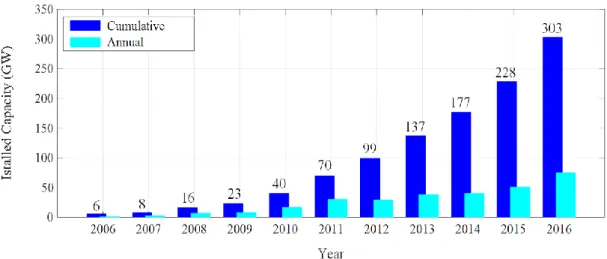
Figure 1.1: Global annual and cumulative installed PV power from 2006 to 2016…………..2
Figure 1.2: Block diagram of a single-stage PV pumping system using DC motor………….3
Figure 1.3: Block diagram of a single-stage PV pumping system using AC motor (a) with and (b) without a step-up transformer……….5
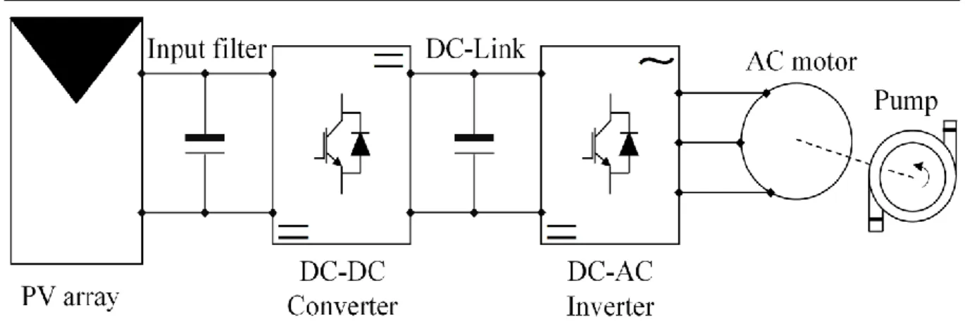
Figure 1.4: Block diagram of a two-stage PV pumping system using AC motor……….6
Figure 2.1: Block diagram of the proposed PV pumping system………...12
Figure 2.2: PV array system………..12
Figure 2.3: The equivalent circuit of a PV cell………..13
Figure 2.4: The equivalent circuit of a PV module………14
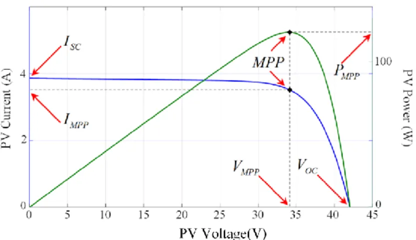
Figure 2.5: I-V and P-V characteristics of pb solar BP SX 120 module under STC………...15
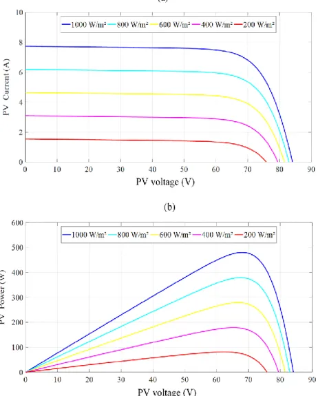
Figure 2.6: (a) I-V and (b) P-V characteristics of PV array under different levels of solar irradiation at 25°C………..16
Figure 2.7: (a) I-V and (b) P-V characteristics of PV array under different temperatures at 1000 W/m²……….17
Figure 2.8: Equivalent boost circuits: (a) switching on and (b) switching off………...18
Figure 2.9: Two-level inverter topology………...19
Figure 2.10: Voltage vectors in the complex plane………...20
Figure 2.11: Coordinate transformation. (a) Current System in a three axis coordinate (a,b,c). (b) Currents expressed in a complex reference frame .……….21
Figure 2.12: Head-flow pump characteristics under different rotor speeds………...23
Figure3.1:(a) Flowchart of the FOCV method, (b) flowchart of the FSCC method………30
Figure 3.2: (a) Flowchart of the P&O algorithm. (b) and (c) Power-voltage characteristics of the PV operating points using the P&O algorithm……….31
Figure 3.3: Basic idea of the IncCon algorithm on a Power-Voltage curve of a PV array…..33
Figure 3.4: Flowchart of the IncCon algorithm……….34
Figure 3.5: Membership function for inputs and output of fuzzy logic controller………….35
Figure 3.6: Example of artificial neural network………...37
Figure 3.7: Bloc diagram of the v/f technique………38
Figure 3.8: Reference frame orientation in FOC………...39
ix
Figure 4.3: The normalized PV power and its derivative variation………...53
Figure 4.4: Flowchart of the FP&O algorithm ………...……...54
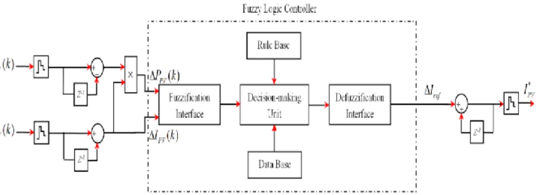
Figure 4.5: Block diagram of the proposed FLC for the FP&O algorithm ………54
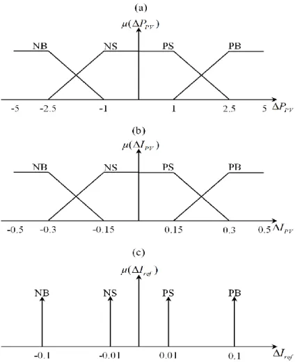
Figure 4.6: Membership function for variables of the FP&O algorithm: (a) and (b) inputs, (c) output ………...………55
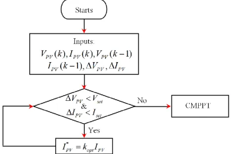
Figure 4.7: PV system behavior with CMPPT algorithm under sudden irradiance decrease ………...………57
Figure 4.8: Proposed solution for CMPPT algorithm under sudden irradiance decrease ………..……….57
Figure 4.9: Operating principle of MPC ..……….58
Figure 4.10: Flowchart of the MPC current controller ...………...59
Figure 4.11: Solar irradiance profile for sudden irradiance changes test ………..61
Figure 4.12: Simulation results of the system of Figure 4.1 with the conventional P&O algorithm ……….………..61
Figure 4.13: Simulation results of the system of Figure 4.1 with the current P&O algorithm based on MPC ………...………62
Figure 4.14: Simulation results of the system of Figure 4.1 with the variable current step size P&O algorithm based on MPC.……….……….…………62
Figure 4.15: Simulation results of the system of Figure 4.1 with the FP&O algorithm based on MPC ……… 63
Figure 4.16: PV Output power waveforms for different MPPT algorithms under sudden irradiance changes ……… 64
Figure 4.17: Solar irradiance profile for ramp irradiance changes test ……… 65
Figure 4.18: PV Output power waveforms for different MPPT algorithms under ramp irradiance changes ……… 65
Figure 4.19: Snapshot of the experimental test bench ………. 66
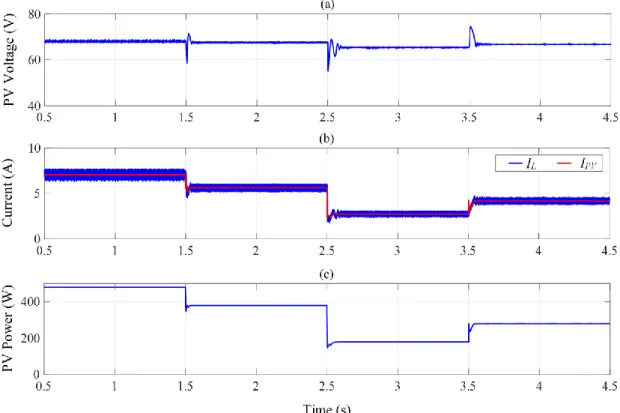
Figure 4.20: Experimental waveforms of the PV voltage, current and output power for sudden irradiance changes, using the conventional P&O ………. 67
x
Figure 4.22: Experimental waveforms of the PV voltage, current and output power for
sudden irradiance changes, using the current P&O based on MPC ……….. 68
Figure 4.23: Zoom-in view of Figure 5.22 during (a) step decrease in the irradiance level (800 W/m²–400 W/m²) and (b) step increase in the irradiance level (400 W/m²–600 W/m²)……… 68
Figure 4.24: Experimental waveforms of the PV voltage, current and output power for sudden irradiance changes, using the variable current step size P&O based on MPC …… 69
Figure 4.25: Zoom-in view of Figure 5.24 during (a) step decrease in the irradiance level (800 W/m²–400 W/m²) and (b) step increase in the irradiance level (400 W/m²–600 W/m²)……… 69
Figure 4.26: Experimental waveforms of the PV voltage, current and output power for sudden irradiance changes, using the FP&O based on MPC ……… 70
Figure 4.27: Zoom-in view of Figure 5.26 during (a) step decrease in the irradiance level (800 W/m²–400 W/m²) and (b) step increase in the irradiance level (400 W/m²–600 W/m²)……… 70
Figure 4.28: Experimental waveforms of the PV voltage, current and output power for ramp irradiance changes, using the conventional P&O ………. 71
Figure 4.29: Experimental waveforms of the PV voltage, current and output power for ramp irradiance changes, using the current P&O based on MPC ……….. 71
Figure 4.30: Experimental waveforms of the PV voltage, current and output power for ramp irradiance changes, using the variable current step size P&O based on MPC ……….. 72
Figure 4.31: Experimental waveforms of the PV voltage, current and output power for ramp irradiance changes, using the FP&O based on MPC ……… 72
Figure 5.1: Schematic diagram of the PV pumping system……….79
Figure 5.2: Proposed control scheme for PV pumping system………..80
Figure 5.3: Flowchart of the proposed P&O CMPPT algorithm………...82
Figure 5.4: Flowchart of the MPC algorithm for current control………...83
Figure 5.5: Block diagram of the proposed FLC………...84
Figure 5.6: FLC membership functions. (a-b) Inputs, (c) Output……….85
xi
under sudden irradiance variations………92 Figure 5.10: PV power waveforms for both conventional P&O and proposed MPPT under sudden irradiance variations………..93 Figure 5.11: DC-link voltage waveforms for both conventional and proposed schemes under sudden irradiance variations………..94 Figure 5.12: Stator currents with zoom waveforms for conventional scheme under sudden irradiance variations………..95 Figure 5.13: Stator currents with zoom waveforms for proposed scheme under sudden irradiance variations………..95 Figure 5.14: (a) Current THD and (b) torque ripple for conventional DTC and PTC under sudden irradiance variations………..96 Figure 5.15: (a) Hydraulic power and (b) pump flow for conventional and proposed schemes under sudden irradiance variations………96 Figure 5.16: PV voltage, current, power and DC-link voltage waveforms for both conventional and proposed schemes under sudden load drop………97 Figure 5.17: Schematic of the HIL setup………...98 Figure 5.18: HIL responses of the PV voltage, current and power for conventional scheme under sudden irradiance variations………99 Figure 5.19: HIL responses of the PV voltage, current and power for proposed scheme under sudden irradiance variations………..99 Figure 5.20: Zoom-in view of Figure 5.19 during (a) step increase in the irradiance level (400 W/m²–600 W/m²) and (b) step decrease in the irradiance level (1000 W/m²–400 W/m²)……….. 100 Figure 5.21: Zoom-in view of Figure 5.20 during (a) step increase in the irradiance level (400 W/m²–600 W/m²) and (b) step decrease in the irradiance level (1000 W/m²–400 W/m²)……… 100 Figure 5.22: HIL responses of the DC-link voltage for conventional scheme under sudden irradiance variations………..………..101 Figure 5.23: HIL responses of the DC-link voltage for proposed scheme under sudden irradiance variations………....101
xii
one-phase stator current for proposed scheme under sudden irradiance variations………..102 Figure 5.26: Zoom-in view of Figure 5.24 of one-phase stator current for conventional scheme under sudden irradiance variations……….…103 Figure 5.27: Zoom-in view of Figure 5.25 of one-phase stator current for proposed scheme under sudden irradiance variations………..…103 Figure 5.28: HIL responses of the hydraulic power and pump flow for conventional scheme under sudden irradiance variations.………..……...104 Figure 5.29: HIL responses of the hydraulic power and pump flow for proposed scheme under sudden irradiance variations………..104 Figure 5.30: Pumped water quantity of conventional and proposed schemes at various pumping heads, during 10 min. (a) simulations, (b) HIL implementations. ………105 Figure 5.31: HIL responses of the PV voltage, current, power and DC-link voltage for proposed scheme under sudden load drop. ……….105 Figure A.1: Block diagram for the developed PV Emulator………..117 Figure A.2: Electrical behavior of the developed PV Emulator using ControlDesk interface………...118
xiii
TABLE 1.1: Advantages and disadvantages of the different types of motor used for PV water
pumping system………...4
TABLE 2.1: Nominal Operating Conditions for pb solar BP SX 120 module………...14
TABLE 3.1: Conventional P&O with fixed perturb step from research survey……….32
TABLE 3.2: The forty-nine fuzzy rules of the fuzzy MMPT……….36
TABLE 4.1: Modified P&O from research survey ………..………50
TABLE 4.2: Fuzzy rules base for FP&O……….……….56
TABLE 4.3: Parameters of the boost converter……….60
TABLE 4.4: Summary of simulation results for sudden irradiance changes……….64
TABLE 4.5: Comparative issues between different MPPT algorithms……….72
TABLE 5.1: Fuzzy rules base for DC-link controller………86
TABLE 5.2: Parameters of the PV pumping system……….90
TABLE 5.3: Comparison results for MPPT techniques……….93
xiv AC Alternative current
ANN Artificial neural network CMPPT Current based MPPT DC Direct current
DTC Direct torque control
EPIA European Photovoltaic Industry Association FCS-MPC Finite control set model predictive control FLC Fuzzy logic control (controller)
FOC Field-oriented control
FOCV Fractional open-circuit voltage FSCC Fractional short-circuit current GA Genetic algorithm
GW Gigawatt
HIL Hardware in the loop
IGBT Insulated gate bipolar transistor
IM Induction motor
IncCon Incremental conductance I-V Current-voltage
MPC Model predictive control
MPP Maximum power point
MPPT Maximum power point tracking P&O Perturb and observe
PCC Predictive current control PI Proportional-integral
PID Proportional-integral-derivative PSO Particle swarm optimization PTC Predictive and flux torque control
PV Photovoltaic
P-V Power-voltage
PWM Pulse width modulation STC Standard test conditions
xvi
c1, c2, c3 Constants depending on the pump geometric dimensions
Cin Boost input capacitor (µF)
F Viscose friction coefficient (N.m.s)
H Head (m)
Hg Geometrical height (m)
Id Diode current (A)
Iinv Inverter input voltage (A)
IL Boost input current (A)
Io Reverse saturation current of the diode (A)
Iph Photovoltaic cell photocurrent (A)
IPV Photovoltaic array output current (A)
ir Rotor current vector (A)
Ir Derived current by the shunt resistance (A)
is Stator current vector (A)
ISC Photovoltaic array short-circuit current
J Moment of inertia of the mechanical shaft (kg.m²)
k Boltzmann constant ( 23
1.38 10 J/K)
kp Pump constant speed
L Boost input inductor (mH)
Lm Magnetizing inductances (H)
Lr Rotor inductances (H).
Ls Stator inductances (H).
n Diode ideality factor
Np Number of cells connected in parallel
Npp Number of modules connected in parallel
Ns Number of cells connected in series
Nss Number of modules connected in series
p Number of pole pairs
q Electronic charge ( 19
1.6 10 C)
Q Flow rate (liter/s or m3/s)
xvii
Rss Stator resistance (Ω)
S Switching signal of the Boost converter
Sa, Sb, Sc Switching signals of the inverter.
T Absolute temperature (K)
Te Electromagnetic torque (N.m)
TL Load torque connected to the IM (N.m)
Ts Sample time of the MPC algorithm (µs)
vaN, vbN, vcN Phase-to-neutral voltages of the inverter (V)
VC Boost output voltage (V)
VDC DC-link voltage (V)
VOC Photovoltaic array open-circuit voltage (V)
VPV Photovoltaic array output voltage (V)
vs Stator voltage vector (V)
Vt Thermal voltage (V)
wi The weight coefficient
θs Stator flux angle (rad)
λ Weighting factor
φr Rotor flux vector (Wb)
φs Stator flux vector (Wb)
φs* Complex conjugate value of the stator flux vector (Wb)
ω Rotor electrical speed (rad/s) ωm Rotor mechanical speed (rad/s)
1
Chapter 1
Introduction
1.1
I
NTRODUCTION TO PHOTOVOLTAICSIn recent years, electricity production from renewable energy sources has attracted great attention in both academia and industry due to the concerns about the global climate change and energy supplies. By 2016, the power generation from renewable energy sources worldwide exceeded 2017 gigawatt (GW) representing approximately 19.3% of global energy consumption [1.1]. Among all the renewable energy sources, solar photovoltaic (PV) energy is increasingly becoming mainstream and competitive with conventional sources of energy. This success is essentially due to the technological developments in solar PV energy system as well as the encouragement of governments incentive programs.
A recent study shows the potential of the solar based energy generation using the PV panel to fulfill the world's energy demand. The annual and cumulative installed PV power capacity worldwide is shown in Figure 1.1 [1.1]. The cumulative installed capacity increased exponentially from 6 GW in 2006 to 303 GW by 2016. It was anticipated on a moderate scale that the cumulative PV capacity would reach 1100 GW by 2030, according to European Photovoltaic Industry Association (EPIA) [1.2]. In 2016, approximately 75 GW of new PV power was installed, which is equivalent to the installation of more than 31000 solar panels every hour [1.1]. The PV energy industry demonstrated an excellent growth rate of more than 30% by the end of 2016. The key reason for this significant development is the increased competitiveness of PV energy because of the cost reduction of PV modules and the introduction of economic incentives or subsidies. This has made PV-generated electrical energy cost-effective and competitive in some regions of the world with good solar irradiation conditions. In addition, PV systems can range from small scale to large scale, making it possible to
2
marine, geothermal, etc.) that have higher capital costs.
Figure 1.1: Global annual and cumulative installed PV power from 2006 to 2016. Generally, photovoltaic systems operate in two different modes: off-grid and grid-connected [1.3-4]. Grid-connected PV energy conversion systems are designed to be able to inject a sinusoidal current into the utility grid. These systems can be grouped into two classes of applications: distributed generation or centralized power systems [1.3-4]. Distributed generation systems are installed to deliver power to a grid-connected customer or directly to the grid. On the other hand, centralized PV power systems offer bulk power in order to reduce
fuel sources dependency and greenhouse gases.
Off-grid PV systems, as their name implies, are designed to function independently of the utility grid [1.3-4]. These systems are composed of several components that convert solar energy into electric energy in a controlled, reliable and efficient manner in order to supply a DC or AC loads. Off-grid PV system is one of the best options for meeting electricity demands in remote or isolation regions where utility power is unavailable or costly. Among the numerous applications of the off-grid PV systems, water pumping system is one of the most promising and attractive in various areas such as domestic and livestock water supplies, small-scale irrigation systems and fish farms.
1.2
B
ACKGROUNDS OF PHOTOVOLTAIC PUMPING SYSTEMSIn various remote and isolation regions, hand pumps or diesel-drive pumps are used for water supply. Diesel pumps consume fossil fuel, affect environment, need more maintenance and are less reliable [1.5]. Due to the cost reduction of PV modules and the developments in
3
received more and more attention and become a reliable alternative for diesel-drive pumps over the last few years.
A PV pumping system is operated independently of the utility grid and is composed of several components such as PV array, power converters, electrical motor, water pump and storage element which can be a battery bank or/and a water tank. PV pumping systems are generally installed with battery bank [1.6], and also can work without chemical storage elements. In battery-less PV pumping systems, the role of batteries is substituted by fluid storage, and steady-state operation depends on the amount of available power, in order to increase the reliability and decrease the cost of such systems (batteries are heavy and expensive and have short lifetime). PV pumping system can be designed to supply either AC or DC motors. For DC motor pumping system, DC motor can be connected directly to the PV array [1.7] or utilize single-stage DC-DC power converters such as the boost [1.8], buck [1.9], buck-boost [1.10] or Cuk [1.11-12] converters. The DC-DC power converters in such systems play a major role in changing the voltage or current level to track the maximum power point (MPP) of the PV array, as shown in Figure 1.2.
Figure 1.2: Block diagram of a single-stage PV pumping system using DC motor. However, the problems associated with DC motors are the high cost and the regular maintenance requirement due to their commutator and brushes. On the other hand, AC motors are generally more reliable and less costly than the DC motors. Many different AC motors have been proposed in PV water pumping [1.12-28]. The main advantages and disadvantages of each of these motors are summarized in Table 1.1. In PV water pumping system driven by AC motor, the MPP is extracted from the PV array to feed the motor-pump set. Single and two stages topologies are commonly used topologies in PV pumping systems using AC motor [1.13-21].
4
pumping system.
Motor Advantages disadvantages
Brushed DC
[1.7-12] Simple speed control
Brushes need to be changed periodically
High initial and maintenance cost Brushless DC
[1.13, 21, 25, 26, 27]
Lower maintenance High efficiency
High initial cost
Possible demagnetization Control complexity Switched reluctance motor [1.22] Lower cost Simple construction No permanent magnets
High iron losses
Possible mechanical resonance Control complexity
Permanent magnet synchronous motor [1.14, 23]
High power density Lower maintenance cost High efficiency
Compact volume
High initial cost High weight Possible demagnetization Open-end winding induction motor [1.18-19] Simple construction
Reduced losses and improved efficiency
High initial and maintenance cost Increased converter cost
Induction motor [1.15, 16, 17, 20,
24, 28]
Simple and rugged in construction
Lower initial and maintenance cost
Lower torque oscillations Available for single or
three-phase supply
Inverters are designed to regulate frequency to
maximize power to the motor in response to changing insolation levels
These motors can handle larger pumping requirements
Control complexity Less efficiency
In single-stage PV pumping system containing AC motor, the system utilizes a single conversion unit (DC-AC power inverter) to track the MPP and interface the PV system to AC motor. In this topology, PV maximum power is delivered into AC motor with high efficiency
5
transformer, which reduces the system efficiency and increases cost, or a PV array with a high DC voltage, this solution is impractical for fractional kilowatt rating (< 1 kW) PV system. Moreover, inverter control is complicated because the control objectives, such as maximum power point tracking (MPPT) and reduction the electromechanical conversion losses, are simultaneously considered. Different types of DC-AC inverters have been applied to enhance and regulate the performance, such as two-level [1.13-17], multilevel [1.18-20] and Z source voltage inverters [1.21]. Figure 1.3 illustratesthe block diagram of a single-stage PV pumping system using AC motor with and without a step-up transformer.
Figure 1.3: Block diagram of a single-stage PV pumping system using AC motor (a) with and (b) without a step-up transformer.
In two-stage PV pumping system containing AC motor, two conversion stages are used. The first stage uses a DC-DC converter (boost [1.23-24], buck-boost[1.25], Cuck [1.26], zeta [1.27] and push–pull [1.28]) for boosting the PV output voltage level and tracking the MPP. A DC-AC inverter is utilized in the second stage to regulate the DC-link voltage and to convert the PV power to AC power for meeting AC motor. The advantages of the two-stage topology lie in the simplicity of designing the control scheme, since the control requirements are disturbed between the two stages. A block diagram of a two-stage PV pumping system using AC motor is illustrated in Figure 1.4.
6
Figure 1.4: Block diagram of a two-stage PV pumping system using AC motor.
1.3
M
OTIVATIONThe design of an effective photovoltaic pumping system without the use of electrochemical storage elements represents a great challenge. It is necessary to deal with the effect of the different operation conditions on the entire energy conversion chain. In other words, it is required to obtain the best performance from each system component over a wide input power range.
However, the output power of a typical PV array can considerably change its position during the day due to the varying atmospheric conditions. Therefore, it is necessary to design a controller that is able to set the value of voltage or current of the PV array and always ensure the working within its maximum power point. Several MPPT controllers have been proposed throughout the literature; nevertheless, most of those controllers have certain disadvantages such as instability, steady-state power oscillation, etc; MPPT schemes that address those challenges suffer from computational burden and increased hardware costs.
Motivated by the above concerns, this thesis focuses on the formulation of new MPPT algorithms that are simple and robust to the atmospheric condition changes. The algorithms shall take into consideration all the challenges and concerns that are presented in the literature (e.g. sudden changing atmospheric conditions, tracking accuracy, etc.)
Furthermore, the electromechanical power conversion in the PV pumping system must be with minimum losses for different atmospheric conditions. Therefore, the DC-AC inverter in the system should have a good DC-link controller and high drive motor performance, which can offer fast transient response and high control accuracy. Moreover, the occurrence of load drops due to any reason might lead to increase the motor voltage in battery-less PV system, which can may damage the motor. Thus, the protection of motor will take into account in the control scheme.
7
The research presented in this thesis is organized into six chapters. The work carried out in each chapter is summarized as follows:
Chapter-2: This chapter decribes the components models of an off-grid photovoltaic system for water pumping. These models are used in the following chapters for control design and simulation work.
Chapter-3: In this chapter, a review of the most widely used maximum power point algorithm for photovoltaic systems is presented. Furthermore, a short overview of the state of the art in control of three-phase induction motor is described in this chapter.
Chapter-4: Two variable current step size perturb and observe maximum power point tracking algorithms for photovoltaic systems are presented in this chapter. The proposed algorithms are employed with a model predictive current controller. Simulation and experimental results are provided to demonstrate the validity and the performance improvement of the proposed algorithms.
Chapter-5: In this chapter, a high-performance control scheme is proposed for battery-less photovoltaic pumping system based on three phase induction motor. The proposed control scheme based on the fuzzy logic and model predictive control strategies. simulations and real-time hardware in the loop implementations are provided to confirm the performance improvement of the proposed control scheme.
Chapter-6: The thesis general conclusion and the author’s contributions are summarized. Possible extensions to the research presented in this thesis are suggested.
8
R
EFERENCES[1.1] Renewable Energy Policy Network for the 21st Centuray (REN21), 2016. Renewables Global Status Report. [Online]. Available: http://www.ren21.net/.
[1.2] European Photovoltaic Industry Association (EPIA), 2012, Global Market Outlook for Photovoltaics until 2016. [Online]. Available: http://www.epia.org/.
[1.3] Ellabban, O., Abu-Rub, H., Blaabjerg F., 2014. Renewable energy resources: current status, future prospects and their enabling technology. Renew. Sustain. Energy Rev.39, 748–764.
[1.4] Madeti, S.R., Singh, S.N., 2017. Monitoring system for photovoltaic plants: A review. Renew. Sustain. Energy Rev. 67, 1180–1207.
[1.5] Periasamy, P., Jain, N.K., Singh, I.P., 2015. A review on development of photovoltaic water pumping system. Renew. Sustain. Energy Rev. 43, 918–925.
[1.6] Rahrah, K., Rekioua, D., Rekioua, T., Bacha, S., 2015. Photovoltaic pumping system in Bejaia climate with battery storage. Int. J. Hydrogen Energy 40, 13665–13675.
[1.7] Kolhe, M., Joshi, J.C., Kothari, D.P., 2004. Performance analysis of a directly coupled photovoltaic water-pumping System. IEEE Trans. Energy Convers. 19, 613–618.
[1.8] Akbaba, M., 2006. Optimum matching parameters of an MPPT unit used for a PVGpowered water pumping system for maximum power transfer. Int. J. Energy Res. 30, 395–409.
[1.9] Elgendy, M.A., Zahawi, B., Atkinson D.J., 2010. Comparison of directly connected and constant voltage controlled photovoltaic pumping systems. IEEE Trans. Sustain. Energy 1, 184–192.
[1.10]El-Khatib, M.F., Shaaban, S., El-Sebah, M.I.A, 2017. A proposed advanced maximum power point tracking control for a photovoltaic-solar pump system. Sol. Energy 158, 321– 331.
[1.11] Algazar, M.M., AL-monier, Hamdy, EL-halim, H.A., Salem, M.E.E.K., 2012. Maximum power point tracking using fuzzy logic control. Int. J. Electr. Power Energy Syst. 39, 21– 28.
9
implementation of FL MPPT control of PV systems based on GA and small-signal analysis. IEEE Trans. Sustain. Energy 8, 279–290.
[1.13] Kumar, R., Bhim, S., 2016. Single stage solar PV fed brushless DC motor driven water pump. IEEE Trans. Ind. Appl. 52, 2315–2322.
[1.14] Antonello, R., Carraro, M., Costabeber, A., Tinazzi, F., Zigliotto, M., 2017. Energy-efficient autonomous solar water-pumping system for permanent-magnet synchronous motors. IEEE Trans. Ind. Electron. 64, 43–51.
[1.15] Betka, A., Attali, A., 2010. Optimization of a photovoltaic pumping system based on the optimal control theory. Sol. Energy 84, 1273–1283.
[1.16] Packiam, P., Jain, N.K., Singh, I.P., 2013. Microcontroller-based simple maximum power point tracking controller for single-stage solar stand-alone water pumping system. Progr Photovolt: Res Appl. 21, 462–471.
[1.17] Chergui, M.-I., Bourahla, M., 2013. Application of the DTC control in the photovoltaic pumping system. Energy Convers. Manage. 65, 655–662.
[1.18] Jain, S., Thopukara, A.K., Karampuri, R., Somasekhar, V.T., 2016. An integrated control algorithm for a single-stage PV pumping system using an open-end winding induction motor, IEEE Trans. Ind. Electron. 63, 956–996.
[1.19] Jain, S., Thopukara, A.K., Karampuri, R., Somasekhar, V.T., 2015. A single-stage photovoltaic system for a dual-inverter-fed open-end winding induction motor drive for pumping applications. IEEE Trans. Power Electron. 30, 4809–4818.
[1.20] Elkholy, M.M., Fathy, A., 2016. Optimization of a PV fed water pumping system without storage based on teaching-learning-based optimization algorithm and artificial neural network. Sol. Energy 139, 199–212.
[1.21] Niapour, S.A.K.H.M., Danyali, S., Sharifian, M.B.B., Feyzi, M.R., 2011. Brushless DC motor drives supplied by PV power system based on Z-source inverter and FL-IC MPPT controller. Energy Conv. Manage. 52, 3043–3059.
[1.22] Bhim, S., Kumar, R., 2016. Solar Powered Water Pumping System Employing Switched Reluctance Motor Drive. IEEE Trans. Ind. Appl. 52, 3949–3957.
10
for photovoltaic pumping system. Trans Inst Measure Control 39, 1–10.
[1.24] Achour, A., Rekioua, D., Mohammedi, A., Mokrani, Z., Rekioua, T., Bacha, S., 2016. Application of direct torque control to a photovoltaic pumping system with sliding-mode control optimization. Electric Power Compon. Syst. 44, 172–184.
[1.25] Bhim, S., Kumar, R., 2016. Simple brushless DC motor drive for solar photovoltaic array fed water pumping system. IET Power Electron. 9, 1487–1495.
[1.26] Kumar, R., Bhim, S., 2017. Solar PV powered BLDC motor drive for water pumping using Cuk converter. IEEE Trans. Ind. Appl. 11, 222–232.
[1.27] Kumar, R., Bhim, S., 2016. BLDC motor-driven solar PV array-fed water pumping system employing zeta converter. IEEE Trans. Ind. Appl. 52, 2315–2322.
[1.28] Vitorino, M.A., de Rossiter, C.M.B., Jacobina, C.B., Lima, A.M.N., 2011. An effective induction motor control for photovoltaic pumping. IEEE Trans. Ind. Electron. 58, 1162– 1170.
11
Chapter 2
Modeling of the Photovoltaic
Pumping System
Components
2.1
I
NTRODUCTIONFollowing the discussion in the previous chapter, a typical configuration of a battery-less photovoltaic (PV) water pumping system, shown in Figure 2.1, is a promising solution for an effective, economic and robust PV pumping system. The system includes a PV generation system, which is a group of series-parallel connected modules (PV array). A passive input filter, a capacitor, which is used to reduce the current and voltage ripple (and hence power) at the PV side, follows the PV array. The input filter is followed by a DC-DC boost converter, which is used to perform the maximum power point tracking (MPPT) of the PV array and elevate its voltage. The DC-DC converter is connected through DC-link (capacitor) to the three-phase two-level inverter. The inverter is used to convert the DC power to AC power and feeds the energy to the utility induction motor (IM) with high power quality. The IM is directly coupled with a centrifugal pump in order to convert the mechanical energy to hydraulic energy.
In order to control the PV pumping system, an essential step consists in modeling the installation components. Hence, this chapter presents the modeling of the proposed PV pumping system components. The mathematical models for PV array, both the boost and invert power converters, IM and centrifugal pump are explicitly developed.
12
Figure 2.1: Block diagram of the proposed PV pumping system.
2.2
P
HOTOVOLTAIC ARRAY MODELINGPhotovoltaic arrays are made of a number of PV modules connected in series and in parallel, where the basic component within module is PV cells. The type of connection depends on the voltage and current levels at which it is desired that the power treating system dedicated to the PV array operate. Figure 2.2 represents a PV array system.
Figure 2.2: PV array system.
2.2.1 Photovoltaic Cell
The PV cell is principally a p-n junction fabricated in a thin wafer of semiconductor. The solar energy is directly converted to electricity through photovoltaic effect. The electrical characteristics of a PV cell are nonlinear and are highly dependent on solar irradiation and
13
[2.1-5]. For simplicity and accuracy, the single diode model is the most studied and used in this work. In this model, the PV cell can be electrically modeled by an equivalent circuit such as the one shown in Figure 2.3, with a photocurrent source in parallel with a diode, a shunt resistance
Rsh and a series resistance Rs.
Figure 2.3: The equivalent circuit of a PV cell.
The model of Figure 2.3 can be mathematically described by the following equation [2.1]:
1 PV s PV PV t V R I PV s nV PV ph d r ph o sh V R I I I I I I I e R (2.1) where: PV
I : is the cell output current (A).
ph
I : is the cell photocurrent (A).
d
I : is the diode current (Shockley equation) (A).
r
I : is the derived current by the shunt resistance (A).
0
I : is the reverse saturation current of the diode (A).
PV
V : is the cell output voltage (V).
s
R : is the cell series parasitic resistance (Ω).
sh
R : is the cell shunt parasitic resistance (Ω).
n: is the diode ideality factor
t
V : is the thermal voltage given by:
t kT V q (2.2) where:
14 q : is the electronic charge (1.6 10 19C)
2.2.2 Photovoltaic Module
Due to low power ratings of each individual PV cell, the cells are connected in series-parallel configuration form a PV module in order to produce required power. Usually, the PV module is rated by its DC output power under standard test conditions (STC) and commercially STC is specified at an irradiance of 1000 W/m² and a 25°C PV cell temperature [2.1]. Figure
2.4 shows the equivalent circuit of a PV module. The nonlinear current-voltage characteristic of the PV module is modeled by the following equation where all cells are identical [2.1]:
( / )
(
/
)
1
(
/
)
s PV s p s PV PV s t N V N N R I s PV s p s nN V PV p ph p o s p shN V
N
N R I
I
N I
N I
e
N
N R
(2.3) where: PVI : is the module output current (A).
PV
V : is the module output voltage (V).
s
N : is the number of cells connected in series
p
N : is the number of cells connected in parallel
Figure 2.4: The equivalent circuit of a PV module.
The PV module considered for this thesis is pb solar BP SX 120 of 120 Wp. The electrical nominal characteristics at STC of this module are listed in Table 2.1. The power versus voltage (P-V) and the current versus voltage (I-V) characteristics of the pb solar BP SX 120 module under STC are shown in Figure 2.5. A PV module can produce the power at a point, called an operating point, anywhere on the I-V curve. Three operating points on the I-V curve are important in defining the performance of a PV module, i.e., the maximum power point, the
15
The maximum power point (MPP) is the point on the I-V curve at which the PV module works with maximum power output.
The short-circuit current point characterized by a zero voltage at the PV module terminals and by a short-circuit current (ISC).
The open-circuit voltage point characterized by a zero current in the PV panel terminals and by an open-circuit voltage (VOC).
Figure 2.5: I-V and P-V characteristics of pb solar BP SX 120 module under STC. TABLE 2.1: Nominal Operating Conditions for pb solar BP SX 120 module [2.6].
PV array Values (STC)
Open-circuit voltage (VOC) 42.1 V
Optimum operating voltage (VMPP) 33.7 V
Short-circuit current (ISC) 3.87 A
Optimum operating current (IMPP) 3.56 A
Maximum power (PMPP) 120 Wp
Temperature coefficient of VOC -0.160 V/°C
Temperature coefficient of ISC 0.065 %/°C
2.2.3 Photovoltaic Array
A PV array is made of a number of PV modules connected in series-parallel arrangement to obtain the desired voltage, current and power. The size of the PV array varies from a single PV module to any number of modules. The PV array output current and voltage can be computed from equations (2.4) and (2.5) respectively [2.7]:
16
PVt ss PV
V N V (2.5)
where:
PVt
I : is the array output current (A).
PVt
V : is the array output voltage (V).
PV
I : is the module output current (A).
PV
V : is the module output voltage (V).
ss
N : is the number of modules connected in series
pp
N : is the number of modules connected in parallel
Figure 2.6: (a) I-V and (b) P-V characteristics of PV array under different levels of solar irradiation at 25°C.
17
Figure 2.7: (a) I-V and (b) P-V characteristics of PV array under different temperatures at 1000 W/m².
The electrical behavior of the PV array is generally represented by the power versus voltage (P-V) and the current versus voltage (I-V) characteristics. A PV array with four pb solar BP SX 120 modules, connected 2×2 in series and parallel, is considered. Figures 2.6 and 2.7
highlighted the strong dependence of the considered PV array performances on the temperature and irradiance levels. The irradiance has a significant effect on the short-circuit current value, as shown in Figure 2.6. On the contrary, the irradiance level has a slight effect on the open-circuit current value. On the other hand, the temperature has a negligible effect on the short-circuit value but it has an important effect on the open short-circuit voltage value, as shown in Figure
2.7. It is worth noting that the temperature usually changes quite slowly, so that the temperature value is often considered a constant with respect to the variation the irradiation level can be subjected to during the day. This simplifying assumption will be also adopted in this thesis.
18
The power electronic converters used in the PV system are receiving more attention due to their flexible controllability and maturing technology. For a PV array, the output power is a DC power and variable as the conditions climatic changes. It cannot be directly connected to the IM. Thus, the PV power should be maximized, and then converted to AC power, which meets the IM requirement. This process has two conversion stages: DC-DC and DC-AC, as shown in Figure 2.1.
2.3.1 DC-DC Boost Converter
The device responsible for maintaining the PV array on the maximum power point, MPP, is the DC/DC converter. Among several options, it was chosen the boost converter. This converter is very simple in structure, design and control and is capable of elevating voltage and controlling the MPPT also, it offers a continuous current at the input. The boost converter can be found implemented with an inductor, a power electronic switch (IGBT), a diode and capacitor [2.8-9]. The equivalent boost circuits during switch-on and switch-off intervals for ideal switch are shown in Figure 2.8.
Figure 2.8: Equivalent boost circuits: (a) switching on and (b) switching off.
When the switch is considered as closed (Figure 2.8(a)), the boost converter operation can be described by the well-known system of equations as follows:
1 L PV d I V dt L (2.6) 1 DC inv d V I dt C (2.7)
19 1 ( ) L PV DC d I V V dt L (2.8) 1 ( ) DC L inv d V I I dt C (2.9)
The aforementioned equations (Eq. 2.6 to 2.9) can be expressed as follows:
1 1 (1 ) L DC PV d I S V V dt L L (2.10) 1 1 (1 ) DC L inv d V S I I dt C C (2.11) where: L
I : is the boost input current (A).
PV
V : is the boost input voltage (V).
DC
V : is the boost output voltage (V).
inv
I : is the boost output current (A).
L: is the boost input inductor (mH).
C : is the boost output capacitor (µF).
S : is the switching signal taking value from the discrete set S [1, 0].
2.3.2 DC-AC Converter
The power circuit of the two-level voltage source inverter (VSI) is presented in Figure 2.9. It uses six bidirectional switches to connect the three-phase IM directly. Each bidirectional switch is composed of an IGBT with a parallel diode, as shown in Figure 2.9. The two switches of each inverter leg must operate in a complementary mode to avoid the short-circuit of the DC-link. It is assumed that the switches and diodes are ideal devices. The inverter output voltages can be expressed in terms of DC-link voltage and switching states as follows [2.10-11]:
aN a DC v S V (2.12) bN b DC v S V (2.13) cN c DC v S V (2.14) where: , , aN bN cN
v v v : are the phase-to-neutral (N) voltages of the inverter (V).
, ,
a b c
20
Considering the unitary vector a, which represents the 120° phase displacement between the phases, the output voltage vector v can be defined as [2.10-11]:
2 2 ( ) 3 aN bN cN v v av a v (2.15) where: 2 /3 1 3 2 2 j ae j (2.16)
Figure 2.9: Two-level inverter topology.
The possible number of combinations for the gating signals (Sa, Sb and Sc) becomes eight
(23), and consequently eight voltage vectors for the inverter are obtained. A space vector
diagram that contains these eight combinations is shown in Figure 2.10.
21
The attractiveness of induction motors (IM) is due to their robustness and operation reliability. They are small in volume and weight, do not require much maintenance, and are of reasonable cost compared to the DC motor. The IM are classified into two types, wound and squirrel-cage, which describes the form of the rotor winding. The squirrel-cage rotor is more mostly applied and it has the rotor winding connection as a short-circuit without any external connections [2.12-13]. The IM considered in this thesis is the squirrel-cage type.
IM contains two main components in its structure: stator winding and rotor winding. The three-phase windings have a spatial phase shift of 120°and suppling by an AC power source, which will create a rotating magnetic field, the so-called stator flux. Then, the constantly changing flux will cause a current induced in the rotor winding, afterward this induced current will generate a magnetic field, the so-called rotor flux. Since both fluxes are opposite to each other, a rotational force is generated to accelerate the rotor until the magnetizing torque is balanced to the load torque [2.13].
To model and analyze such a motor, space vectors as complex state variables should be used because of their convenience and efficiency. In power electronic system, a three-phase current system can be represented by a three-axis coordinate system, as presented in Figure
2.10(a). This three-phase system can be described by using a complex reference frame. Figure
2.10(b) illustrates the equivalent representation.
Figure 2.11: Coordinate transformation. (a) Current System in a three axis coordinate (a,b,c). (b) Currents expressed in a complex reference frame .
A three-phase stator currents system, with angular frequency ωo, can be defined in a fixed
22 2 sin 3 sb o i I t (2.18) 4 sin 3 sb o i I t (2.19)
The transformation from a three- to a two-phase system of the stator currents is presented by:
2 2 ( ) 3 s sa sb sb i i ai a i (2.20) 2 /3 1 3 2 2 j ae j (2.21) 2 4 /3 1 3 2 2 j a e j (2.22) The same coordinate transformation aforementioned is used for the electromagnetic variables. Therefore, the equations of an induction motor can be described in any arbitrary reference frame rotating at an angular frequency ωk [2.13]:
s ss s s k d v R i j dt (2.23) 0 r r r ( k ) r d R i j dt (2.24) s L is s L im r (2.25) r L ir r L im s (2.26) * 3 ( ) 2 e s s T p m i (2.27) where: , s r
L L andL : are the stator, rotor, and magnetizing inductances, respectively (H). m ss
R andR : are the stator and rotor resistances ( ).r s
v andi : are the stator voltage and current vectors. s r
i : is the rotor current vector (A). s
andr: are the stator and rotor flux vectors (Wb). : is the rotor electrical speed (rad/s)
e
23
* s
: is the complex conjugate value of the stator flux vector.
For ωk = 0 the coordinate system is stator-fixed, i.e., the coordinates are given in the
system. The mechanical rotor speed dynamics are given as:
m e L m d J T T F dt (2.28) where: m
: is the rotor mechanical speed (rad/s).
L
T : is the load torque connected to the IM (N.m).
J : is the moment of inertia of the mechanical shaft (kg.m²). F : is the viscous friction coefficient (N.m.s).
The electrical rotor speed ω is related to the mechanical rotor speed ωm as demonstrated
below:
m p
(2.29)
2.5
C
ENTRIFUGAL PUMP MODELINGA centrifugal pump is one of the most used pump type in water pumping applications, due to its advantage such as suitable for small to high head, less torque to start, large flow rates, low cost and high efficiency compared to other pump types [2.14-15]. The centrifugal pump is used for converting the mechanical energy into hydraulic energy. As it has been previously mentioned, it is coupled directly to the IM and opposes a load torque TL [ 2.14]:
2
L p m
T k (2.30)
where:
p
k : is the pump constant speed. m
: is the rotor mechanical speed (rad/s).
The centrifugal pump is characterized by its head-flow rate performance curve at the nominal speed. The head-flow curves at different speeds are commonly estimated using the affinity laws (similarity laws) of the pump [2.14-16]. These laws state that the flow rate is directly proportional to the pump speed, the head is proportional to the square of the speed, and the hydraulic power is proportional to the cube of the speed. The head-flow characteristics of a
24 model [2.16]: 2 2 1 m 2 m 3 H c c Qc Q (2.31) where: H : is the head (m).
Q : is the flow rate (liter/s or m3/s).
1, 2
c c andc : are constants depending on the pump geometric dimensions. 3
The pump performance is estimated by specifying a load curve; the head-flow characteristic of the pipe network can be given by [2.16]:
2
g
H H Q (2.32)
where:
g
H : is the geometrical height, which is the difference between the free level of the water
to pump and the highest point of the canalization (m).
: is a constant depending on conduit diameter and on all frictional losses of the pipe network.
Figure 2.12: Head-flow pump characteristics under different rotor speeds.
2.6
C
ONCLUSIONThe aim of this chapter is to describe the components models of the proposed battery-less photovoltaic pumping system, which will be used in the following chapters for the system control and simulation work. First, the photovoltaic cell, module and array, and their characteristic curves have been described. Additionally, the power converters used in the proposed pumping system were presented to illustrate their power circuit and to model
25
facilitate and understand the operation of motor control. Finally, the centrifugal pump model and their head-flow characteristics under different rotor speeds were presented.
26
R
EFERENCES[2.1] Villalva, M.G., Gazoli, J.R., Filho, E.R., 2009. Comprehensive approach to modeling and simulation of photovoltaic arrays. IEEE Trans. Power Electron. 24, 1198– 1208.
[2.2] Farivar, G., Asaei, B., 2011. A new approach for solar module temperature estimation using the simple diode model. IEEE Trans. Energy Convers. 26, 1118–1126.
[2.3]Rekioua, D., Matagne, E., 2012. Optimization of Photovoltaic Power Systems. Springer Verlag.
[2.4] Bishop, J.W., 1988. Computer simulation of the effects of electrical mismatches in photovoltaic cell interconnection circuits. Solar Cells 25, 73–89.
[2.5] Kassis, A., Saad, M., 2010. Analysis of multi-crystalline silicon solar cells at low illumination levels using a modified two-diode model. Solar Energy Materials and Solar Cells 94, 2108–2112.
[2.6] BP Solar Arrays Datasheet, 2001. [Online]. Available: http://www.eastcountysolar. com/pdf/BPSX120.pdf.
[2.7] Alajmi, B., 2013. Design and control of photovoltaic systems in distributed generation. PhD. thesis, University of Strathclyde.
[2.8] Abu-Rub, H., Malinowski, M., Al-Haddad, K., 2014. Power electronics for renewable Energy systems, transportation and industrial applications. John Wiley & Sons.
[2.9] Luo, F. L., Ye, H., 2004. Advanced DC-DC converters. CRC Press Boca Raton.
[2-10] Rodriguez, J., Pontt, J., Silva, C.A.C.A., Correa, P., Lezana, P., Cortes, P., Ammann, U., 2007. Predictive current control of a voltage source inverter. IEEE Trans. Ind. Electron. 54, 495–503.
[2.11] Cortes, P., Ortiz, G., Yuz, J.I., Rodriguez, J., Vazquez, S., Franquelo, L.G., 2009. Model predictive control of an inverter with output filter for UPS applications. IEEE Trans. Ind. Electron. 56, 1875–1883.
[2.12] Giri, F., 2013. AC Electrical Motors Control. John Wiley & Sons.
27
[2.14] Betka, A., Attali, A., 2010. Optimization of a photovoltaic pumping system based on the optimal control theory. Sol. Energy 84, 1273–1283.
[2.15] Betka, A., Attali, A., 2004. Performance optimization of a photovoltaic induction motor pumping system. Renew. Energy 29, 2167–2181.
[2.16] Achour, A., Rekioua, D., Mohammedi, A., Mokrani, Z., Rekioua, T., Bacha, S., 2016. Application of direct torque control to a photovoltaic pumping system with slidingmode control optimization. Electric Power Compon. Syst. 44, 172–184.
28
Chapter 3
Literature Review
3.1
I
NTRODUCTIONThe efficiency of solar photovoltaic (PV) energy conversion to electrical energy is relatively low, and the characteristics of the PV array are highly nonlinear and are dependent on the environmental conditions. Therefore, a maximum power point tracker (MPPT) is essential to solve these issues and to ensure that the PV pumping system operate at its maximum power point (MPP). On the other hand, electromechanical power conversion in the proposed PV pumping system is provided by a three-phase induction motor (IM) fed by a two-level inverter. Assuming that the PV system is operating at the MPP during different operating conditions, it is necessary also to ensure electromechanical power conversion with minimum loss at all operating points.
In this chapter, the basic concepts of MPPT algorithms are described and analyzed; these concepts include the fractional open-circuit voltage (FOCS) and short-circuit current (FSCC) methods, perturb and observe (P&O) algorithm, incremental conductance (IncCon) algorithm, and an overview on other advanced concepts is presented. In addition, this chapter gives a short review of the state of the art in electrical IM drive systems control and highlights known problems in these methods.
3.2
M
AXIMUM POWER POINT TRACKING ALGORITHMSThe MPPT unit is a power conversion system with a suitable control algorithm that allows extracting the maximum power from a PV array. The maximization of the delivered power can be achieved by regulating the current drawn from the PV array or the voltage across it to yield

![TABLE 3.2: The forty-nine fuzzy rules of the fuzzy MPPT [3.24].](https://thumb-eu.123doks.com/thumbv2/123doknet/3392406.98262/55.892.166.726.286.726/table-fuzzy-rules-fuzzy-mppt.webp)