HAL Id: hal-02464930
https://hal.archives-ouvertes.fr/hal-02464930
Submitted on 4 Feb 2020HAL is a multi-disciplinary open access archive for the deposit and dissemination of sci-entific research documents, whether they are pub-lished or not. The documents may come from teaching and research institutions in France or abroad, or from public or private research centers.
L’archive ouverte pluridisciplinaire HAL, est destinée au dépôt et à la diffusion de documents scientifiques de niveau recherche, publiés ou non, émanant des établissements d’enseignement et de recherche français ou étrangers, des laboratoires publics ou privés.
Influence of carbon characteristics on Sb/carbon
nanocomposites formation and performances in Na-ion
batteries
Cristina Nita, Julien Fullenwarth, Laure Monconduit, Loïc Vidal, Camelia
Matei Ghimbeu
To cite this version:
Cristina Nita, Julien Fullenwarth, Laure Monconduit, Loïc Vidal, Camelia Matei Ghimbeu. Influence of carbon characteristics on Sb/carbon nanocomposites formation and performances in Na-ion batter-ies. Materials Today Energy, 2019, 13, pp.221-232. �10.1016/j.mtener.2019.05.009�. �hal-02464930�
1
Influence of carbon characteristics on Sb/Carbon nanocomposites
formation and performances in Na-ion batteries
Cristina Nita1,2,3, Julien Fullenwarth4,5, Laure Monconduit 4,5, Loïc Vidal1,2, Camélia Matei
Ghimbeu1,2,5, *
1Université de Haute-Alsace, Institut de Science des Matériaux de Mulhouse (IS2M), CNRS
UMR 7361, F-68100 Mulhouse, France
2Université de Strasbourg, F-67081 Strasbourg, France
3 Center for Advanced Laser Technologies (CETAL), National Institute for Lasers, Plasma
and Radiation Physics, Atomistilor 409 bis, RO-77125, Magurele, Romania
4ICG/AIME (UMR 5253 CNRS), Université Montpellier II CC 15-02, Place E. Bataillon,
34095 Montpellier Cedex, France
5 Réseau sur le Stockage Electrochimique de l'Energie (RS2E), CNRS FR3459, 33 Rue Saint
Leu, 80039 Amiens Cedex, France
*Corresponding author:
E-mail: camelia.ghimbeu@uha.fr
2
Abstract
The impact of carbon characteristics (structure, porosity and surface chemistry) on the Sb/Carbon composites formation and electrochemical performances in Na-ion batteries is investigated herein. Mesoporous and non-porous hard carbon heated at different temperatures were used to support Sb nanoparticles prepared via a ball-milling/thermal reduction synthesis approach. The mesoporous carbon presenting higher surface area and oxygen functional groups induce the formation of small Sb nanoparticles (< 5 nm) well dispersed in the carbon network. For the hard carbon, the increase in the annealing temperature from 1100 to 1500°C leads to more organized structure but lower porosity and surface functionalities having as consequence the increase of Sb nanoparticle size and the particle agglomeration. The best electrochemical performances vs. Na were achieved for hard carbon/Sb composite treated at 1100°C which combines several advantages like dispersed Sb nanoparticle, low surface area and good conductivity (360 mAh g-1 after 200 cycles). Regarding the long-term capacity
retention, for all materials a drastic decay was observed starting to 300 cycles and associated to the Sb particle size agglomeration and growth during repeated charge/discharge cycles and amorphization of Sb particles as demonstrated by post-mortem analyses.
3
1. Introduction
Lithium-ion batteries (LIBs) are widely used for portable electronic devices such as phones, laptops, cameras and more recently emerged for large-scale energy storage applications for electrical vehicles and intermittent solar and wind energy sources. However, the increase demand for Li-ion batteries in an economical and geographical context where the Li sources become more and more scarce and localized only in few areas of the world requires tremendous efforts to find alternative cost-effective solutions for current LIBs. In the recent years, sodium-ion batteries (NIBs) have been brought into the spotlight due to the rich Na resources in the Earth’s crust which may offer a low-cost energy system for near future. Despite the rather similar working principles of LIBs and NIBs, Na+ is not able to
insert into graphite anode due to its larger size, steric and thermodynamic limitations [1-3], leading to poor performances. Therefore, many studies were focused on hard carbon materials [4-6] having disordered structure and larger interlayer distance compared to graphite. Various types of hard carbons issue from the pyrolysis of monomers, polymers, biomass and natural resources have been proposed and capacities up to 300 mAh g-1 could be achieved in some
cases via a storage mechanism involving adsorption and intercalation of Na+ in the carbon
porosity and nanographitic domains [7-9]. In order to achieve higher gravimetric and volumetric capacities, anode materials based on alloying materials have been studied as well as anodes for Na-ion batteries. Their charge storage mechanism relies in the formation of alloys with sodium during the charging of the anode leading to much higher and attractive capacities than carbon. Among the reported alloying materials, antimony, tin, and phosphorus are considered promising for Na-ion batteries thanks to their appealing theoretical capacities [10;11]. Antimony (Sb) exhibits a high theoretical capacity (660 mAh g-1) upon full sodiation
to Na3Sb alloy, good kinetic performance and high volumetric energy density compared to
4
volume changes during sodiation/desodiation which induces particle growth and agglomeration, pulverization, loss of electrical contacts and thus performance degradation. Such large volume changes of alloy materials may limit their applications for NIBs. Lately, several solutions have been proposed to overcome this problem including the nanostructuration of the active material, the use of a second metal or the use of carbon materials in order to buffer the Sb volume expansion.
The nanostructuration by synthesizing nanoparticles, nanocrystals or nanorods can facilitate the electrolyte ion diffusion ensuring faster kinetics and high-rate performance [12-14]. The use of metals such Al, Fe, Cu, Sn [15-21] to minimize the volume changes and to prevent aggregation during cycling has been also reported, however, except Sn, most of these metals are electrochemically inactive and would scarify the capacity in some extent. Taking into account this aspect, several works have been focused on carbon materials which are able not only to buffer the active material volume expansion and to avoid agglomeration but also to provide electrical conduction and electrolyte diffusion pathways. A literature table gathering the main forms of Sb and Sb/C composites, their synthesis methods along with their electrochemical performances is provided in Table 1. Darwiche et al. used commercially available bulk Sb electrode and mixed with vapor ground carbon fibers and carbon black conductive additives which resulted in high performance at a high current rate (550 mAh g-1
at 4C, 160 cycles) [22]. Electrospinning was used to anchor Sb nanoparticles on self-sustained carbon nanofibers films derived from polyacrilonitrile (PAN) polymer [23-25] and the capacities were comprised between 274 and 650 mAh g-1. Liao et al. [26] reported a
hydrothermal approach to obtain Sb particles in an amorphous carbon matrix which exhibited high capacity of 622 mAh g-1, at 100 mA g-1 current rate after 100 cycles. Other approaches
such as sol-gel, impregnation of a carbon with a Sb salt followed by chemical reduction, polymerization in the presence of a Sb salt have been explored and yielded distinct materials
5
with capacities ranging between 241 and 554 mAh g-1 (see Table 1) [14;27-30]. Some simple
approach consisting in mixing of a carbon with metallic antimony by ball milling has been demonstrated as well. Zhou et al. [31] used multiwall carbon nanotubes (MWCNTs) and Sb powder and obtained uniformly mixture of Sb NPs on MWCNTs by a wet milling approach. The materials exhibited a high capacity of 502 mAh g-1 at 100 mA g-1 current rate and 120
cycles. Qian et al. [32] prepared Sb/C nanocomposites by mechanical milling of commercial Sb powder with a carbon black (Super P) and demonstrated a high capacity of 610 mAh g-1 at
2 Ag-1 current rate over 100 cycles. Ramireddy et al. [33] prepared Sb/C composites in a
similar manner by using graphite as carbon support. The particle size could be tuned from 1 to 50 nm by adjusting the carbon and Sb weight ratio in the mixture allowing to obtain high a stable capacity at high current rates. Ji et al. [34] proposed a self-thermal-reduction approach of potassium antimony(III)-tartrate to form Sb/C rod composite which exhibited low capacity and fading after ~ 70 cycles, i.e., 150 mAh g-1 at 100 mA g-1 for 200 cycles, due to the
material volume expansion and fragmentation. Such limitation could be overcome by using potassium chloride during the synthesis which leaded to dual carbon/Sb nanoparticle composite (Sb-O-C/C) with high capacity (500 mAh g-1) and good capacity retention for more
than 200 cycles (Table 1).
Considering these above mentioned works, it is clear that the carbon materials play an important role in the stabilization of Sb nanoparticles during synthesis and cycling, in improving the electronic conductivity and in fine in improving the electrochemical performance of SIBs. Despite that, most reported works are devoted to new synthesis routes to obtain Sb/C nanocomposites by employing different carbon and Sb sources and no systematic studies concerning the influence of carbon support characteristics on the formation of Sb nanoparticles and their performances in SIBs have been reported to our knowledge.
6
Moreover, long term cycling is rarely discussed although of prime importance for developing robust energy storage systems.
Table 1. Literature review on Sb/C hybrid materials synthesis methods and performances for
Na-ion batteries.
Materials Synthesis method Electrochemical performances vs. Na Refs.
Current density (mA g-1) Crev (mAh g-1) Cycle number Bulk Sb Commercial 4C 550 160 [22]
Sb/C Sol-gel with citric acid 4C 115 50 [35]
Sb/C Sol-gel with chitosan 500 403 100 [36]
Sb/C Sol-gel 100 423 200 [27] Sb@N-doped C sheets Sol-gel 50 305 60 [30] Sb/CNFs Impregnation/chemical reduction 100 542 100 [37]
Sb/graphenes Chemical reduction 100 241 10 [29]
Sb/graphene/CNFs Sb/CNFs Sb/CNFs Electrospinning 100 200 100 274 600 650 100 80 300 [23] [24] [25] Sb nanorode arrays Template
electrodeposition
1000 574 250 [13]
Sb/porous carbon Salt template 100 456 500 [38]
Sb nanocrystals One-pot colloidal 660 580 100 [14]
Sb/amorphous C Hydrothermal route 100 622 110 [26]
Sb/MWCNTs Wet milling 200 400 100 [31]
Sb/C black Mechanical milling 2000 610 100 [32]
Sb/C graphite Mechanical milling 100 420 100 [33]
Sb/C yolk-shell Polymerization 50 554 200 [39]
Sb/N-doped C Ionic liquids 100 440 100 [28]
NanoSb/C Aerosol spray pyrolysis 100 385 500 [12]
Sb/C roads Sb-O-C/C Self-thermal-reduction Thermal-reduction 100 100 150 500 200 200 [34] [34]
7
Therefore, we report in this work a simple ball milling procedure involving carbon materials and antimony salt followed by thermal reduction to obtain Sb/C nanocomposites. The influence of carbon texture, structure and surface chemistry on the Sb particle size/dispersion was evaluated by several techniques along with their electrochemical performances. Carbons possessing higher surface area and larger amount of functional groups lead to smaller and better dispersed Sb NPs and improved electrochemical performances. The carbon/Sb anodes tested for Na-ion batteries exhibits high reversible capacity after the first charge-discharge cycle up to 639 mAh g-1 and a stable capacity retention up to 200 cycles
with a capacity of 360 mAh g-1. Moreover, irreversible capacity was successfully reduced by
using carbon support with low surface area and low surface chemistry. The capacity fading at long term cycling is discussed as well in terms of materials characteristics.
2. Materials and methods
2.1 Materials Synthesis
In a first step, the carbon support, i.e., a mesoporous carbon and a non-porous carbon called herein hard carbon was prepared by sol-gel polymerization. The mesoporous carbon was obtained as described previously [40], briefly phloroglucinol (the carbon source, 1.65g) and pluronic F-127 (the structure directing and pore generating agent) were dissolved in an acidic ethanol solution, followed by the glyoxal cross-linker addition (1.62 mL). The obtained polymer gel after 3 days aging is dried followed by thermal pyrolysis at 900°C under Ar. The preparation of the hard carbon support was the same as for the mesoporous carbon, the only difference is the absence of pluronic F-127 in the mixture. Three annealing temperatures were used, i.e., 1100, 1300 and 1500oC and the as-prepared carbons denoted: MC@900- for the
8
In a second step, the C/Sb materials were prepared by using a simple ball milling of carbon supports with antimony acetate (Sb (CH3COO)3) for 1h, followed by a thermal reduction in
presence of Ar:H2 gas mixture (1:1, 10L/h flow rate). The materials were heated at 250oC for
1h to allow the melting of the precursor, followed by the increase of the temperature up to 500oC for 1h (heating rate 5k/min) to decompose and reduce the precursor to metallic Sb. A
schematic illustration of the synthesis pathway can be found in Figure 1. The Sb calculated loading was kept constant (60 wt.%) and the resulting materials denoted Sb/MC (for mesoporous carbon support) and Sb/HC@T, with T=1100, 1300, 1500oC (for hard carbon
support). Phloroglucinol Glyoxal 900 oC Mesoporous carbon (MC) Pluronic F127 Hard carbon (HC) 1100-1500oC Phenolic Resin/Template Phenolic Resin 2. Reduction 500°C, H2/Ar 1. Ball-milling Sb(CH3COO)3 Hard carbon/ Sb Mesoporous carbon/Sb
Figure 1. Schematic representation of the synthesis protocol developed for carbon/Sb
materials preparation.
2.2 Materials characterization
The crystalline structure of the materials was characterized by X-ray powder diffraction (XRD) technique, by using a powder diffractometer D8 ADVANCE A25 from Bruker in Bragg-Brentano reflexion geometry θ – θ. Complementary microstructure analysis were performed by Raman spectroscopy in a backscattering geometry using a LabRAM BX40 (Horiba Jobin-Yvon) microspectrometer equipped with a HeNe excitation source (wavelength 532 nm). The material surface morphology/structure was investigated with a JEOL
ARM-9
200F transmission electron microscope working at 200 kV. The surface chemistry was assessed by X-ray photoelectron spectroscopy (XPS) with a VG Scienta SES 200-2 spectrometer equipped with a monochromatized Al Kα X-ray source (1486.6 eV) and a hemispherical analyzer. The pass energy was 100 eV. The bulk surface chemistry was determined by temperature programmed desorption coupled with mass spectrometry (TPD-MS) [41]. The carbon is heat it under vacuum up to 950°C with a heating rate of 5°C/min resulting in the decomposition of oxygen functional groups into CO and CO2 gases which are
monitored by a mass spectrometer. Additionally, water and H2 are evolved as well from the
material. The amount of evolved gases can be obtained by time integration of the TPD curves by comparison with calibrated gases prior the analyses.
The amount of antimony in the composite was determined by thermogravimetric analysis (TGA) conducted on a TGA 851 (Mettler-Toledo) instrument by heating the C@Sb composite under air (100 ml/min), from 30oC up to 900oC with a 10oC/min rate. The textural
properties of the carbon/Sb materials were evaluated using N2 and CO2 sorption isotherms by
using a Micromeritics ASAP 2420 set-up. The materials were outgassed at 200°C under vacuum for 12h prior to the analyses. The BET specific surface area (SSA) was calculated in the relative pressure range, P/P0, of 0.05-0.3.
2.3 Electrochemical characterization
The electrode was prepared by mixing the carbon/Sb materials (70%) with carbon black (10%) and vapor grown carbon fibers - VGCF-S (10%) as conductive additives, and carboxymethylcellulose - CMC (10%) as binder. A quantity of 0.4 ml distillated water was added over the materials and homogeneously mixed by ball-milling for 1h. A film with a thickness of 100µm was laid down on a copper foil, dried at room temperature for 4h and at 100oC under vacuum for other 12h.
10
The electrochemical performances of carbon support and carbon/Sb composites as negative electrode for Na-ion batteries were studied in coin cells assembled in an argon filled glove box. The electrolyte was NaClO4, 1M propylene carbonate (PC) as solvent and vinyl
carbonate (VC)(1%) and fluoroethylene carbonate (FEC) (5%) as additives, which have proven to have a positive effect on the cycling of Sb particles [22]. The galvanostatic charge/ discharge measurements were carried out at room temperature on Mac pile (Biologic SA and MTI) battery testing system at room temperature. The capacity is reported per gram of C/Sb composite.
3. Results and discussion
3.1 Carbon support characterization
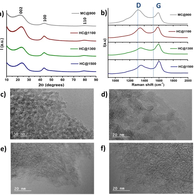
The structure of carbon materials may impact the Na insertion but also their conductivity, therefore was analysed in detail by several complementary techniques. The XRD patterns for the carbon supports (Figure 2a) exhibit three broad diffraction peaks, corresponding to carbon with low degree of graphitization. A slight increase of the peak intensity could be observed for the hard carbons treated at temperature higher than 1100oC. The TEM pictures
(Figure 2c, d, e, f) revealed a disordered structure for both mesoporous and hard carbons, but graphitic layers short domains are more obvious for the hard carbon, especially for the one treated at 1500oC. Figure 2b shows the Raman spectra of carbon support. Two typical bands,
D (1363 cm−1) and G (1600 cm−1), are visible and usually employed for the assessment of the
disorder in the graphitic structure [42;43]. For mesoporous carbon, the D band is more intense and broader than the G band while for hard carbons the increase of the temperature induces an increase in the intensity of G band, sign of a more ordered structure. The ratio of ID/IG is 1.29
for the mesoporous carbon and decreases with the thermal temperature from 0.94 for HC@1100 down to 0.74 for HC@1300 and 0.73 for HC@1500, respectively. The Raman
11
results confirm the XRD and TEM analyses which showed an increase of the carbon organization by increasing the temperature.
1000 1200 1400 1600 1800 2000 HC@1100 I( a.u ) Raman shift (cm-1 ) HC@1500 HC@1300 MC@900 10 20 30 40 50 60 70 80 90 HC@1500 HC@1300 HC@1100 I ( a.u.) 2 (degrees) MC@900
a)
b)
c)
d)
D
G
f)
e)
002 100 110Figure 2. XRD patterns (a) and Raman spectra for carbon supports (b); TEM pictures for
MC@900 (c), HC@1100 (d), HC@1300 (e), HC@1500 (f)
The assessment of the carbon surface chemistry is one of the important factors since is impacting the interactions with the metal precursor salt and the stability of the particles during the synthesis but also the interactions with the electrolyte. The composition and the surface chemistry of the carbon supports (<10 nm thickness) was determined by XPS measurements
12
and gathered in the Table 2. In the case of mesoporous carbon (MC@900), the amount of carbon is 95.7 at% and that of oxygen 4.3 at%. The deconvolution of the C1s peak (Figure
S1a, Supporting Information) reveled the existence of ether (-C-OR), carbonyl (-C=O) and
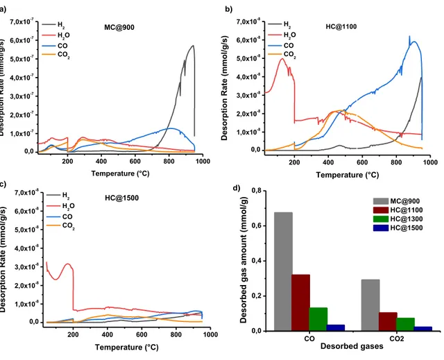
carboxyl (-COOR) groups at 286.1, 287.2 and 288.4 eV, respectively. The major contributions come from C-OR, COOR and then C=O. Similar groups and trend in term of quantities was found for hard carbon as well (Figure S1b, c, d, Supporting Information). Concerning the amounts of oxygen in hard carbon, they were found to be higher than for mesoporous carbon and only slightly decreasing with the increase in the annealing temperature. This observation is rather unexpected since the increase in the temperature generally leads to the decomposition of functional groups and to the decrease in the amount of oxygen. However, it should be reminded that this composition is only in the extreme surface of the materials and the composition it might be different in the bulk. For this reason, the TPD-MS technique was employed to study the materials oxygen functionalities. The carbon materials were heated under vacuum and the evolved gases (H2, CO, CO2 and H2O) recorded
as a function heating temperature. The functional oxygenated groups decomposed in CO and CO2 gases and their release temperature provides insights on their nature. Typically, the CO2
is derived from the decomposition of acidic groups, i.e., carboxyl or/and anhydride groups while CO is obtained by decomposition of more basic groups such as, carbonyl, phenol, ether and quinone groups [44].
For the mesoporous carbon, MC@900, a large CO desorption peak ranged between 200 and 900°C is recorded (Figure 3a) suggesting the existence of a large variety of oxygenated groups such as anhydrides, phenols, ethers and quinones [41;45;46]. The CO peak is more intense and narrower between 600 and 900°C, indication of more predominant basic groups in the material such as ethers and quinones. The CO2 desorption profile is less intense
13
group [41;45;46]. These observations are in good agreement with the XPS results. Water release is also observed (100 – 600°C), which can be assigned to physisorbed water in carbon porosity at low temperature and to chemisorbed water or in-situ formed water at higher temperatures. In addition, an intense peak of hydrogen is evolved at temperatures higher than 800°C suggesting the cleavage of the C-H bonds and the carbon structural organization. In the case of HC@1100 carbon, rather similar CO profiles are observed while the CO2 profile is on
the contrary much larger indicated a greater number of anhydrides and lactones (Figure 3b) besides the carboxyl groups. As for the water profile, the low temperature peaks are intense probably due to the high amount of micropores in this material, as will be demonstrated latter on. It is worth to note that hydrogen evolution is less important than in the case of mesoporous carbon due to the higher synthesis temperature and better organized structure. For HC@1500 (Figure 3c), the peaks are less intense compared to the other materials sign of a poor surface chemistry.
By integration of CO and CO2 desorption peaks, the amounts of the oxygenated functional
groups can be determined (Table 2, Figure 3d). As a general trend, the amounts of CO are higher than CO2 for all materials, in well agreement with the desorption profiles intensity. The
highest amounts of CO and CO2 are obtained for mesoporous carbon while for hard carbon
they are decreasing with the increase of the annealing temperature (Figure 3d). The overall COx (CO + CO2, Table 2) quantities are following the same trend, and they are rather
different from the one determined by XPS, confirming that the oxygen groups in the surface are rather different than in the bulk. It is possible that the higher amounts of water in the hard carbon may induce higher oxygen amount in the materials when analyzed by XPS. In the case of mesoporous carbon, functional groups maybe placed inside the pores and probably not accessible to be measured by XPS, resulting in lower oxygen amounts [47].
14 200 400 600 800 1000 0,0 1,0x10⁻⁸ 2,0x10⁻⁸ 3,0x10⁻⁸ 4,0x10⁻⁸ 5,0x10⁻⁸ 6,0x10⁻⁸ 7,0x10⁻⁸ HC@1100 De so rp tion Ra te ( mmo l/ g /s) Temperature (°C) H2 H2O CO CO2 CO CO2 0,0 0,2 0,4 0,6 0,8 De so rb ed ga s am o u n t ( mmo l/ g ) Desorbed gases MC@900 HC@1100 HC@1300 HC@1500 200 400 600 800 1000 0,0 1,0x10⁻⁸ 2,0x10⁻⁸ 3,0x10⁻⁸ 4,0x10⁻⁸ 5,0x10⁻⁸ 6,0x10⁻⁸ 7,0x10⁻⁸ HC@1500 De so rp tion Ra te ( mmo l/ g /s) Temperature (°C) H2 H2O CO CO2 200 400 600 800 1000 0,0 1,0x10⁻⁷ 2,0x10⁻⁷ 3,0x10⁻⁷ 4,0x10⁻⁷ 5,0x10⁻⁷ 6,0x10⁻⁷ 7,0x10⁻⁷ MC@900 D eso rp ti o n R ate (mmo l/ g /s) Temperature (°C) H2 H2O CO CO2 b) a) d) c)
Figure 3. TPD-MS desorption profiles of mesoporous carbon, MC@900 (a) hard carbon,
HC@1100 (b), HC@1500 (c) and the CO and CO2 desorbed quantities from all carbons (d).
The textural properties of the carbon support were evaluated by nitrogen adsorption/desoption isotherms (Figure S2, Supporting Information). For MC@900, the N2 type IV isotherms
characteristic to mesoporous materials were observed, confirming the role of Pluronic F-127 in the formation of mesopores (Vmeso = 0.47 cm3 g-1). The existence of some micropores is
indicated, as well, by the presence of the points in the low relative pressure region (Vmicro =
0.17 cm3 g-1) with a surface area of 412 m2 g-1.In case of HC@T, the isotherms correspond
more to type I, but not many points are observed in the low-pressure region, indicating the character almost non-porous for these materials in line with the SSA below 4 m2 g-1 (Table 2).
15
Table 2. Properties of the mesoporous and hard carbon/Sb materials. Specific surface area
(SSA) determined by BET method, chemical composition assessed by XPS, COx functional
groups obtained by TPD-MS and Sb amount determined by TGA analyses.
3.2 Carbon/Sb hybrid materials
Taking into account the results obtained in our previous study on the influence of Sn loading [48], we considered 60 wt.% amount of Sb, the appropriate loading to obtain a good compromise between the Sb loading and the Sn particle homogeneity in the material.
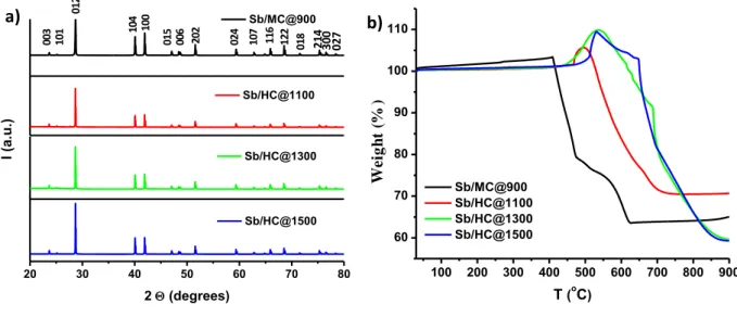
The XRD patterns of the carbon/Sb composites exhibit several peaks which were indexed to the Sb metallic phase (COD 9008575) (Figure 4a). Therefore, the implemented synthesis pathway allowed to decompose the antimony acetate precursor into antimony oxides and their further reduction under hydrogen and by carbo-reduction reactions results in the formation of metallic Sb, according to the following reactions:
Sb(CH3COO)3 => Sb2O3 + (C–COOH) + H2O+COx (1)
Sb2O3 + H2 +C => Sb +H2O +COx (2) Material SSA m2 g-1 C at. % O at. % COx mmol g-1 Sb wt.% MC@900 412 95.7 4.3 0.97 - HC@1100 4.0 93.7 6.3 0.42 - HC@1300 0.1 94.3 5.7 0.20 - HC@1500 0.6 94.4 5.6 0.057 - Sb/MC@900 208 - -- - 51 Sb/HC@1100 6 - - 56 Sb/HC@1300 2 - - - 47 Sb/HC@1500 1 - - - 47
16 100 200 300 400 500 600 700 800 900 60 70 80 90 100 110 We igh t l o ss ( %) T (oC) Sb/MC@900 Sb/HC@1100 Sb/HC@1300 Sb/HC@1500 20 30 40 50 60 70 80 Sb/MC@900 Sb/HC@1100 Sb/HC@1300 I ( a.u.) 2 (degrees) Sb/HC@1500 003 101 012 104 100 006 202 024 107 122 018 214 300 027 015 116 a) b) We ig h t (% )
Figure 4. XRD patterns of carbon/Sb hybrid materials prepared using different carbon
supports (mesoporous and hard carbon) and annealing temperatures for hard carbon (a) and TGA analysis performed in air on the carbon/Sb hybrid materials (b).
The composition and thermal/chemical stability of carbon/Sb hybrid materials were determined by TGA in air (Figure 4b). The TGA curve for the mesoporous carbon presents a slight increase of the mass weight followed by two main mass weight losses observed at ~ 400 and 600 °C, associated to the oxidation of carbon (C+O2 CO2). Regarding the
Sb/HC@T, the gain in mass before 500oC is much more evident. In both cases, this gain could
be associated to the oxidation of the Sb particles (Sb +O2 SbO2), in agreement with other
works [26], [29]. In contrast with the mesoporous material, where this increase was not well visible (more likely because the particles are situated in the pores), for the hard carbon/Sb composites, the particles situated on the carbon surface determines firstly the oxidation of the metallic Sb, and then the carbon combustion. The derivatives for the TGA curves (not shown here) present mainly one exothermic peak for each material, but also one endothermic peak. The peaks are shifted to higher temperature in function of the thermal treatment temperature of the carbon support. The presence of two peaks corresponding to the carbon combustion could indicate that the size of the Sb particles (small particles/aggregates) or the place where
17
they are located (inside/outside of the pores) influence differently the carbon combustion. The real amount of Sb was calculated by taking into account the SbO2 quantity obtained after the
TGA at 900oC in air (Figure S3, Supporting Information) and the Sb/O atomic ratio. The
values presented in Table 2 indicate that the synthesis route allowed preparing materials with high loading of Sb and close to the calculated ones. Insights on the structure and morphology of the different materials were assessed by STEM in dark field. The Sb particle size have a great influence on Na+ diffusion pathways and on the storage mechanism as indicated in the
introduction part. When using mesoporous carbon framework, the Sb nanoparticles are homogeneous distributed in the carbon framework (Figure 5a) and they have small size (< 5 nm) as better visualized in the STEM images provided in the Figure S4a, Supporting Information. . For Sb/HC@T the homogeneity seems to strongly depend on the annealing temperature of the carbon support. The Sb/HC@1100 material presents a homogeneous distribution of Sb nanoparticles (Figure 5b) with slightly higher size than for mesoporous carbon and some larger particles observed (10-20 nm) as well as seen in Figure S4b, Supporting Information. A closer look on a large particle by HRTEM allow to visualize the crystallite lattice fringes, however, on small particles it was difficult to observe it (Figure S5, Supporting Information). Increasing the annealing temperature of the carbon support to 1300 and 1500oC, respectively, a significant increase in particle size is observed (up to 20 nm),
18
Figure 5. STEM images for Sb/MC@900 (a), Sb/HC@1100 (b), Sb/HC@1300 (c) and Sb/HC@1500 (d).
The precise determination of the particle size evolution is rather difficult to realize due to the high density of the particles. However, this behavior may be explained on one hand by the decrease of the amount of oxygen groups of carbon with the increase of the annealing temperature which decreases the hydrophilicity of carbon support and of the functional groups/ active sites serving as anchoring points for the antimony acetate precursor. On the other hand, an important role on the agglomeration of Sb particles could be played by the decrease of the pore volume and size with the temperature, as will be seen in the following part.
19
The textural properties of the composite materials were evaluated by N2 physisorption
technique at 77K (Figure 6) and the corresponding textural data are gathered in Table 2. The surface area and the pore size/volume are carbon characteristics which may strongly impact not only the composite synthesis but also its electrochemical performances. A high pore volume and surface area can be beneficial since it may allow a good diffusion of the electrolyte but also can accommodate the Sb nanoparticles during synthesis and electrochemical cycling. On the contrary, the high surface area may induce undesirable reactions of the support with the electrolyte. Therefore, such characteristics must be determined. Type IV isotherms characteristic to mesoporous materials were observed in the case of the Sb/MC@900. The textural properties, namely the specific surface area and the pore volume decreased after the Sb addition from 412 to 208 m2 g-1(Table 2)and respectively,
from 0.64 to 0.34 cm3 g-1. 0,0 0,2 0,4 0,6 0,8 1,0 0 2 4 6 50 100 150 200 250 0 5 10 15 20 25 30 0,0000 0,0002 0,0004 0,0006 0,004 0,008 0,012 A d s o rb e d N 2 V o lu m e ( cm 3 /g ) Relative Pressure (P/P0) Sb/MC@900 Sb/HC@1100 Sb/HC@1300 Sb/HC@1500 P o re V o lu m e ( cm 3 /g ) Pore diameter (nm) Sb/MC@900 Sb/HC@1100 Sb/HC@1300 Sb/HC@1500 a) b)
Figure 6. N2 adsorption/ desorption isotherms (a) and pore size distribution (b) for carbon/Sb
20
For the Sb/HC@T materials, surprisingly, the Sb addition induces a slight increase of the textural properties (SSA and pore volumes) compared to the values for the HC@T support (Table 2). The Sb/HC@1300 and Sb/HC@1500 materials present an increase of the adsorbed nitrogen volume at high relative pressures (P/P0) indicating an inter-particle porosity due to
the larger amount of Sb particles on the carbon surface. The pore size distribution (PSD) (Figure 6b) determined from the adsorption branch of N2 isotherm indicates the existence of
both micro- (0.6 nm) and meso-pores (7.5 nm) for all composite materials but also pores larger than 20 nm corresponding rather to the inter-particle porosity.
3.3 Electrochemical performances
The electrochemical tests for carbon/Sb materials were performed at C/10 constant current rate in the voltage range of 0.01-1.5V (vs. Na/Na+). Firstly, the carbon supports were tested in
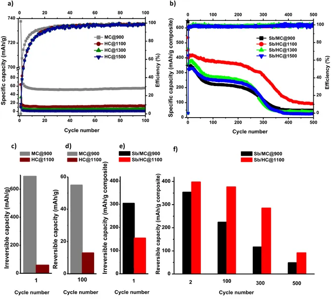
the same conditions as the composites materials for comparison purposes in order to evaluate their contribution to the capacity (Figure 7a). The carbon supports revealed a high irreversible capacity in the first cycles, representing 91-94% from the initial capacity no matter the material. However, it is worth to note that in the case of mesoporous carbon, MC@900, the irreversible capacity is significantly much higher than for the hard carbon, HC@1100 i.e., 738 mAh g-1 vs. 64 mAh g-1 (Figure 7c and Table S1). This may be related in
large extent to the higher specific surface area but also to the richer surface chemistry of mesoporous carbon which induce more electrolyte decomposition and SEI layer formation [49;50]. Such higher irreversible capacity of the carbon support may negatively impact the irreversible capacity of the MC@Sb composite as well.
Regarding the reversible capacity, it was found to be dependent on the carbon support. The mesoporous support presents a higher reversible capacity (55 mAh g-1) after the 100 cycles
21
annealing temperature of the carbon from 13 mAh g-1 for HC@1100 to 4 mAh g-1 for
HC@1500 (Figure 7a). This decrease of the capacity with the temperature could be associated with the higher hydrophobicity for the materials treated at high temperatures and the slight increase of the graphitization level of the carbon. The reversible capacity values are particularly very low for hard carbon materials since usually materials with similar specific surface area and structure delivers much higher capacity (> 200 mAh g-1) [51]. Such different
behavior may come from the different electrochemical conditions used herein (binder, electrolyte, additives) which were optimized for Sb anodes [22] and which do to favor good performances for hard carbons. Considering the low reversible capacity of the pristine carbons, their contribution to the capacity of the C/Sb composite materials can be therefore neglected. For all carbons supports, the coulombic efficiency is quite low in the first cycle, but after 20 cycles it strongly increases to more than 90% and after 30 cycling reaches 100%. Generally, for the C/Sb composite materials, the irreversible capacity was significantly reduced compared to the carbon supports (Figure 7b and Table 3). This can be understood by the lower amount of carbon contained in the composites (~ 50 %) which limits the irreversible reactions with the electrolyte. Moreover, the irreversibility of the composite materials which use hard carbon as support was successfully reduced compared to the mesoporous materials (48% for Sb/MC@900 and 25-29% for Sb/HC@T) (Figure 7e). This decrease can be related to the lower SSA in case of the hard carbon, which in contact with the electrolyte reduce the SEI formation. A slight contribution to the irreversible capacity could come also from the small quantity of Sb oxides covering the Sb nanoparticles a well-known phenomenon for nanoparticles in contact with air (see Raman spectra provided in Figure S6, Supporting
22
Table 3. Electrochemical performances for mesoporous and hard carbon/Sb materials.
Material C 1st discharge C 1st charge C irrev (mAh g -1) C rev 2nd cycle (mAh g-1) Crev 100th cycle (mAh g-1) Crev 300th cycle (mAh g-1) Crev 500th cycle (mAh g-1) Sb/MC@900 639 335 48% 354 224 117 49 Sb/HC@1100 535 381 29% 398 377 285 92 Sb/HC@1300 462 347 25% 362 271 95 37 Sb/HC@1500 416 311 25% 323 253 114 28
Concerning the reversible capacity in the first cycle, the Sb/MC@900 presents the highest specific capacity (639 mAh g-1), while for Sb/HC@T the values decreases with the annealing
temperature from 535 mAh g-1 for Sb/HC@1100 to 419 mAh g-1 for Sb/HC@1500. It is worth
noting that in most of the literature works regarding Sb/C composites, the cycling performances are presented only for a limited number of cycles (Table 1), which do not allow to assess the long-term behavior of such materials. We have therefore tested the materials for the long-term cycling, and during the 75 cycles a decrease of the capacity is observed for all materials. After the 250th cycle, another strong decay is noticed and for 500 cycles the
materials kept only about 8% from their initial capacity for Sb/MC@900, Sb/HC@1300 and Sb/HC@1500 and 17% for Sb/HC@1100, respectively. The most well performing material from cycle stability point of view is Sb/HC@1100 material which, moreover exhibits the highest reversible capacity. A comparison between the reversible capacities of Sb/HC@1100 and Sb/MC@900 is presented in Figure 7e, f. The better performances obtained for the hard carbon/Sb composite as support could be explained by a good compromise between the low
23
surface area and the good dispersion of the Sb particles in the carbon framework. Both these parameters may impact the performances. The Sb particles size are small and well dispersed in both composites ensuring short electrolyte pathways and insertion of Na. However, the carbon supports are rather different in terms of porosity (specific surface area and pore size distribution). The mesoporosity of MC carbon allow better diffusion of the electrolyte but in the same time the associated high surface area induce high irreversible capacity and probably thick and unstable SEI layer which are detrimental during long cycle. On the contrary, the low surface area in the case of HC ensures a low irreversible capacity related to an efficient SEI. The better structural organization of the HC carbon (see Figure 2) may also have a positive impact on the conductivity of Sb nanoparticles [52]. Moreover, it has been shown [53] that the increase of the annealing temperature of hard carbon improves its electronic conductivity. However, for the hard carbon supports annealed at higher temperature, i.e.,1300 and 1500oC
even if they possess low surface area and better structure organization, they lose faster their performances due to the larger and agglomerated Sb particles (Figure 5c, d) situated most probably on the carbon surface triggering more agglomeration during sodiation/desodiation process.
24 0 100 200 300 400 1 Ir reve rsible cap acity (m Ah /g com p o sit e) 0 100 200 300 400 1 Sb/MC@900 Sb/HC@1100
Cycle number Cycle number Cycle number Cycle number
500 300 2 R ev er si b le c ap ac it y (mA h /g c o mp o si te ) 100 Sb/MC@900 Sb/HC@1100 0 200 400 600 Ir reve rsible cap acity (m Ah /g ) 1 0 20 40 60 MC@900 HC@1100 MC@900 HC@1100 Rever sible cap acity (m Ah /g ) 100 0 100 200 300 400 500 0 100 200 300 400 500 600 0 20 40 60 80 100 0 20 40 60 80 700 720 740 MC@900 HC@1100 HC@1300 HC@1500 Cycle number Specific capac ity (mAh/g) 0 20 40 60 80 100 0 20 40 60 80 100 E ff ic ie nc y (% ) E ff ic ie nc y (% ) Specific capac ity (mAh/g co mposite) Cycle number Sb/MC@900 Sb/HC@1100 Sb/HC@1300 Sb/HC@1500 0 100 200 300 400 500 0 20 40 60 80 100 a) b) c) d) e) f)
Figure 7. Electrochemical performances of the carbon support and carbon/Sb materials
(voltage range 0.01-1.5V (Na+/Na), C/10 current rate). The specific discharge capacity vs. the
cycle number and the coulombic efficiency for the carbon supports (a). The specific discharge capacity vs selected cycle numbers and the coulombic efficiency (b), the comparison between the performances (irreversible and reversible capacity vs. cycle number) of mesoporous and hard carbon supports and their Sb based composites vs. Na (c, d, e, f).
Taking into account the as-presented evolution, we can conclude that there is no need to use sacrificial templates in order to create mesopores in the carbon framework. The advantage of the mesopores for improving the electrolyte diffusion and the accommodation of
25
Sb particles it is contra balanced by its higher SSA which determines higher irreversibility. Moreover, there is no reason to treat the carbon support at high temperature (1300oC and
1500oC, respectively) since the Sb agglomeration phenomena negatively impact the
electrochemical performances. The coulombic efficiency of the C/Sb composite materials reaches fast 100% (after 10 cycles), which means that parasitic reactions take place because of the electrolyte degradation are limited after first cycles. That being said, the Sb/HC@1100 could be considered the optimal composite for the proposed applications.
Nevertheless, to better understand this fading behavior which is rarely discussed,
Figures 8 presents the galvanostatic curves and derivative curves for Sb/MC@900 and
Sb/HC@1100 for several specified cycles. For the Sb/MC@900 (Figure 8a, c), the first discharge profile shows a gradual voltage drop to 0.4 V, followed by a plateau and another strong decrease down to 0.01 V, delivering a discharge capacity of 639 mAh g-1. In the same
time, 55% of the inserted Na can be reversibly desodiated, giving a charge capacity of 335 mAh g-1. The subsequent discharge curves are very different compared to the first discharge
because of the formation of SEI on the surface of the anode. The differences in shape and potential between the first insertion and the following ones are similar to the classically observed ones for Sb system and likely attributed to the “electrochemical grinding” occurring in the first discharge. This phenomenon induces the active material particle size grinding leading to smaller and sometimes amorphous particles [20], [54]. The next curves are almost overlapped indicating the good reversibility of the chemical reactions in the electrode. For the discharge curve which corresponds to the 75th cycle, a faster decrease of the potential is
observed, corresponding to the significant decrease of the capacity which took place during the first 75 cycles.
26
The Figure 8b, d presents the galvanostatic and derivative curves for Sb/HC@1100 for selected cycles. The first discharge profile shows a rapid voltage drop to 0.8 V, followed by a gradual decrease down to ≈ 0.45V (Figure 8b).
0 100 200 300 400 500 600 0,0 0,3 0,6 0,9 1,2 1,5 Sb/MC@900 P o te n tia l ( v s . N a /N a + ) ( V )
Specific capacity (mAh/g composite)
1st cycle 2nd cycle 3rd cycle 75th cycle 300th cycle 500th cycle 0 100 200 300 400 500 600 0,0 0,3 0,6 0,9 1,2 1,5 Sb/HC@1100 1st cycle 2nd cycle 3rd cycle 75th cycle 300th cycle 500th cycle P o te n tia l ( v s . N a /N a + ) ( V )
Specific capacity (mAh/g composite)
0,0 0,3 0,6 0,9 1,2 1,5 -6000 -3000 0 3000 6000 1st cycle 2nd cycle 3rd cycle 75th cycle 300th cycle 500th cycle Sb/HC@1100 d X /dV Potential (vs. Na/Na+ ) (V) a) b) c) d) 0,0 0,3 0,6 0,9 1,2 1,5 -6000 -3000 0 3000 6000 1st cycle 2nd cycle 3rd cycle 75th cycle 300th cycle 500th cycle Sb/MC@900 d X /dV Potential (vs. Na/Na+ ) (V) 0 .9 4 0.9 1 0 .8 1 0.7 8 0.70 0.53 0.47 0.45 0 .1 1 0 .7 9 0 .8 5 0 .9 8 0.9 2 0,40 0.44 0.53 0.69 0.21
Figure 8. The galvanostatic (a, b) and derivatives (c, d) curves for Sb/MC@900 and
Sb/HC@1100 materials for the specified cycles (voltage range 0.01-1.5V (Na+/Na), C/10
current rate).
A plateau is observed at this value, followed by another strong decrease down to 0.01V, delivering a discharge capacity of 535 mAh g-1. The next curves present the same voltage
drop to 0.8 V, from here a slow continue decrease of the voltage is observed down to 0.45, followed by a strong decrease to 0.01V. The curves corresponding to the second and third cycles are overlapped indicating the reversibility of the chemical reactions, while the curve
27
for the 75th cycle presents faster decrease to 0.01V. The 3 cathodic peaks observed in the
derivative curves (Figure 8d) situated between 0.38 and 0.72V correspond to the multi-step formation of amorphous NaxSb and crystalline Na3Sb alloys at the end of discharge [22]
according to the following equations:
Sb + xNa+ + xe- ↔ NaxSb (3)
NaxSb + (3-x) Na+ + (3-x) e- ↔ Na3Sb (4)
For the first 3 anodic cycles, an intense peak is seen at 0.78 V and a small oxidative peak at 0.90 V which splits in the 75th cycle into two peaks located at 0.81 and 0.91 V characteristics
to the desodiation of crystalline Na3Sb. At 300 cycles, only one peak is observed which is
shifted at 0.94 V, is broader and less intense, and further vanished at 500 cycles. The same behavior is seen for Sb/MC@900, but in this case, the 0.94 V peak almost disappeared after the 300 cycles. The disappearing of the peaks can be related to the observed fading of the two materials which occurred earlier for Sb/MC@900 compared to Sb/HC@1100. The reason behind the disappearing of the electrochemical peaks may be the amorphisation of Sb particles as observed in the literature [22].
In order to better understand the changes which took place in the anode during the charge-discharge cycling, STEM analyses were performed on the post mortem electrodes (Figure 9). Two materials were selected which present very different physico-chemical properties in order to distinguish easier between the factors which could impact the electrochemical performances. So, the STEM images were taken for Sb/MC@900 (Figure
9a) and Sb/HC@1500 electrodes recovered after 500 cycles (Figure 9b). The post mortem
Sb/MC@900 material revealed a good homogeneity of Sb particles in the carbon matrix, comparable with that of the material before cycling (Figure 5a), confirming the well confinement of the Sb particles in the mesoporous structure. However, few agglomerates of
28
particles are formed during the cycling as well which are no more electrochemically active after several cycles and could be partially responsible for the decay of the reversible capacity after 75 cycles. Moreover, the decay after 300 cycles could be also associated to the amorphization on Sb nanoparticles. On the contrary, the post mortem Sb/HC@1500 electrode shows more agglomerated particles (Figure 9b) compared to Sb/MC@900 composite, the material being more prone to form agglomerates even before the cycling (higher particle sizes and agglomerates before cycling, Figure 5d).
a) b)
Figure 9. STEM images after 350 cycles for Sb/MC@900 (a) and Sb/HC@1500 (b).
In addition, the benefits of the better dispersed particles for the Sb/MC@900 material competes with the weakness due to the high surface area of the mesoporous carbon, which interacts with the electrolyte and forms continuously the SEI layer, originating a significant decay of the capacity in cycling. For the Sb/HC@1500, the irreversible capacity is significantly lower, thanks to the lower textural properties of the carbon support, but due to the larger Sb particles which are partially agglomerated [55] the material loses in performances. Therefore, both mesoporous and hard carbon could be successfully used as support to prepare carbon/Sb anodes for Na-ion batteries, by making a balanced compromise between the amount and the distribution of the Sb particles in the carbon matrix, and the
29
characteristics of carbon support. Well dispersed particles obtained at moderate Sb loading (~50%) and annealing temperatures of the carbon matrix could favor the diffusion of the electrolyte on the anode surface. On the other hand, the carbon porosity allows the particle confinement and accommodate the particles limiting their agglomeration during the cycling, but cannot totally prevent it, few aggregates being formed no matter the carbon support (more for hard carbon). However, in the same time this porosity could react with the electrolyte and form a SEI layer inducing a high irreversible capacity. Therefore, small and well dispersed Sb particles on a suitable carbon support is not sufficient to ensure long term cycling. The emplacement of the particles in the carbon network can be as well an important factor. Ji et al. [34] succeed to avoid the fading of Sb/C composites by embedding carbon Sb nanoparticles in an amorphous carbon network. Such confinement of Sb particles in the carbon structure rather than in the carbon porosity or in the surface may better limit the particle growth and aggregation. Such hypothesis can be sustained by other two works [14], [25], where the Sb particles are trapped in the carbon structure by simultaneous synthesis of Sb and carbon in one-pot synthesis providing long term cycling performances.
Conclusions
Carbon materials presenting different structure, porosity and surface chemistry were synthesized by eco-friendly sol-gel methods and used to support Sb nanoparticles by ball milling-thermal reduction approach. The influences of the presence/absence of mesopores and the annealing temperature on the physico-chemical and electrochemical properties of carbon/Sb hybrid materials was investigated. Small and well dispersed Sb nanoparticles were obtained for mesoporous carbon and hard carbon supports treated at low temperature. By increasing the annealing temperature from 1100°C to 1500°C, the carbon porosity and surface oxygen-based functionalities decreases inducing the Sb particle size increase and
30
agglomeration. The electrochemical tests performed at a C/10 current rate in a voltage range of 0.01-1.5 V (Na/Na+) prove a successfully reduction of the irreversible capacity of
mesoporous carbon and hard carbon from ≈ 91-94% to 48% and ~ 25-29% by preparing Sb/MC@900 and Sb/HC@T hybrid materials. The reversible capacity reached 535 mAh g-1
for Sb/HC@1100 after the first cycle, while the other composites delivered lower capacities. For the long term cycling, the Sb/HC@1100 composite combining both low surface area, small Sb nanoparticles and optimal structure exhibited the most stable behavior up to 300 cycles, while in the case of the other materials fading occurred in the first 75 cycles. In addition, for all materials a drastically capacity fading is observed at around 300 cycles with almost complete loss of the capacity. This behavior could be attributed to the Sb particle size agglomeration and amorphization during cycling.
Acknowledgements
The authors acknowledge the financial support of this work from University of Haute-Alsace, France and European Union’s Horizon 2020 Program (project NAIADES, call: LCE10-2014, Contract no. 646433). Jean-Marc Le Meins, Samar Hajjar-Garreau and Bénédicte Réty are acknowledged for the help provided with the XRD, XPS and TPD-MS analyses.
Data availability
The raw/processed data required to reproduce these findings cannot be shared at this time due to legal or ethical reasons.
Competing financial interests
The authors declare no competing financial interest
Appendix A. Supporting information
Supplementary data associated with this article can be found in the online version at doi:XX.XXXX/XXX.
31
References
[1] M. Dahbi, N. Yabuuchi, K. Kubota, K. Tokiwa, S. Komaba, Negative electrodes for Na-ion batteries. Physical Chemistry Chemical Physics 16 (2014) 15007-15028.
[2] B.L. Ellis, L.F. Nazar, Sodium and sodium-ion energy storage batteries. Current Opinion in Solid State & Materials Science 16 (2012) 168-177.
[3] S.W. Kim, D.H. Seo, X.H. Ma, G. Ceder, K. Kang, Electrode Materials for Rechargeable Sodium-Ion Batteries: Potential Alternatives to Current Lithium-Ion Batteries. Advanced Energy Materials 2 (2012) 710-721.
[4] D. Saurel, B. Orayech, B. Xiao, D. Carriazo, X. Li, T. Rojo, From Charge Storage Mechanism to Performance: A Roadmap toward High Specific Energy Sodium-Ion Batteries through Carbon Anode Optimization. Adv Energy Mater 1703268 (2018). [5] T. Wu, M. Jing, Y. Tian, L. Yang, J. Hu, X. Cao, X. Hou, X. Ji, Surface-Driven Energy
Storage Behavior of Dual-Heteroatoms Functionalized Carbon Material. Adv Funct Mater 1900941 (2019).
[6] H. Hou, C. Banks, M. Jing, Y. Zhang, X. Ji, Carbon Quantum Dots and Their Derivative 3D Porous Carbon Frameworks for Sodium-Ion Batteries with Ultralong Cycle Life. Adv Mater 27 (2015) 7861-7866.
[7] C.M. Ghimbeu, J. Gorka, V. Simone, L. Simonin, S. Martinet, C. Vix-Guterl, Insights on the Na+ ion storage mechanism in hard carbon: Discrimination between the porosity, surface functional groups and defects. Nano Energy 44 (2018) 327-335.
[8] H.Y. Kang, Y.C. Liu, K.Z. Cao, Y. Zhao, L.F. Jiao, Y.J. Wang, H.T. Yuan, Update on anode materials for Na-ion batteries. Journal of Materials Chemistry A 4 (2016) 7962. [9] A. Ponrouch, A.R. Goni, M.R. Palacin, High capacity hard carbon anodes for sodium
ion batteries in additive free electrolyte. Electrochemistry Communications 27 (2013) 85-88.
[10] J.Y. Hwang, S.T. Myung, Y.K. Sun, Sodium-ion batteries: present and future. Chemical Society Reviews 46 (2017) 3529-3614.
[11] Y.C. Liu, X.B. Liu, T.S. Wang, L.Z. Fan, L.F. Jiao, Research and application progress on key materials for sodium-ion batteries. Sustainable Energy & Fuels 1 (2017) 986-1006.
[12] M. He, K. Kraychyk, M. Walter, M.V. Kovalenko, Monodisperse Antimony Nanocrystals for High-Rate Li-ion and Na-ion Battery Anodes: Nano versus Bulk. Nano Letters 14 (2014) 1255-1262.
[13] L.Y. Liang, Y. Xu, C.L. Wang, L.Y. Wen, Y.G. Fang, Y. Mi, M. Zhou, H.P. Zhao, Y. Lei, Large-scale highly ordered Sb nanorod array anodes with high capacity and rate capability for sodium-ion batteries. Energy & Environmental Science 8 (2015) 2954-2962.
32
[14] N. Zhang, Y.C. Liu, Y.Y. Lu, X.P. Han, F.Y. Cheng, J. Chen, Spherical nano-Sb@C composite as a high-rate and ultra-stable anode material for sodium-ion batteries. Nano Research 8 (2015) 3384-3393.
[15] Z.-L. Xu, S. Yao, J. cui, L. Zhou, J.-K. Kim, Atomic scale, amorphous FeOx/carbon nanofiber anodes for Li-ion and Na-ion batteries. Energy Storage Mater 8 (2017) 10-19. [16] X.Q. Xie, S.J. Wang, K. Kretschmer, G.X. Wang, Two-dimensional layered compound
based anode materials for lithium-ion batteries and sodium-ion batteries. Journal of Colloid and Interface Science 499 (2017) 17-32.
[17] S.P. Wu, R.Y. Ge, M.J. Lu, R. Xu, Z. Zhang, Graphene-based nano-materials for lithium-sulfur battery and sodium-ion battery. Nano Energy 15 (2015) 379-405.
[18] L.P. Wang, L.H. Yu, X. Wang, M. Srinivasan, Z.C.J. Xu, Recent developments in electrode materials for sodium-ion batteries. Journal of Materials Chemistry A 3 (2015) 9353-9378.
[19] H. Li, Y.H. Wang, J.L. Jiang, Y.Y. Zhang, Y.Y. Peng, J.B. Zhao, CuS Microspheres as High-Performance Anode Material for Na-ion Batteries. Electrochimica Acta 247 (2017) 851-859.
[20] A. Darwiche, M.T. Sougrati, B. Fraisse, L. Stievano, L. Monconduit, Facile synthesis and long cycle life of SnSb as negative electrode material for Na-ion batteries. Electrochemistry Communications 32 (2013) 18-21.
[21] J.H. Choi, C.W. Ha, H.Y. Choi, S.M. Lee, Carbon embedded SnSb composite tailored by carbothermal reduction process as high performance anode for sodium-ion batteries. Journal of Industrial and Engineering Chemistry 60 (2018) 451-457.
[22] A. Darwiche, C. Marino, M.T. Sougrati, B. Fraisse, L. Stievano, L. Monconduit, Better Cycling Performances of Bulk Sb in Na-Ion Batteries Compared to Li-Ion Systems: An Unexpected Electrochemical Mechanism. Journal of the American Chemical Society 135 (2013) 10179.
[23] K.F. Li, D.W. Su, H. Liu, G.X. Wang, Antimony-Carbon-Graphene Fibrous Composite as Freestanding Anode Materials for Sodium-ion Batteries. Electrochimica Acta 177 (2015) 304-309.
[24] M.N. Zhu, X.Z. Kong, H.L. Yang, T. Zhu, S.Q. Liang, A.Q. Pan, One-dimensional coaxial Sb and carbon fibers with enhanced electrochemical performance for sodium-ion batteries. Applied Surface Science 428 (2018) 448-454.
[25] Y.J. Zhu, X.G. Han, Y.H. Xu, Y.H. Liu, S.Y. Zheng, K. Xu, L.B. Hu, C.S. Wang, Electrospun Sb/C Fibers for a Stable and Fast Sodium-Ion Battery Anode. Acs Nano 7 (2013) 6378-6386.
[26] S. Liao, G.Z. Yang, C.X. Wang, Ultrafine Sb nanoparticles embedded in an amorphous carbon matrix for high-performance sodium ion anode materials. Rsc Advances 6 (2016) 114790-114799.
33
[27] G.H. Wang, X.H. Xiong, Z.H. Lin, C.H. Yang, Z. Lin, M.L. Liu, Sb/C composite as a high-performance anode for sodium ion batteries. Electrochimica Acta 242 (2017) 159-164.
[28] X. Xu, Z.F. Dou, E.L. Gu, L. Si, X.S. Zhou, J.C. Bao, Uniformly-distributed Sb nanoparticles in ionic liquid-derived nitrogen-enriched carbon for highly reversible sodium storage. Journal of Materials Chemistry A 5 (2017) 13411-13420.
[29] Y. Yi, H.W. Shim, S.D. Seo, M.A. Dar, D.W. Kim, Enhanced Li- and Na-storage in Sb-Graphene nanocomposite anodes. Materials Research Bulletin 76 (2016) 338-343. [30] X.L. Zhou, Y.R. Zhong, M. Yang, M. Hu, J.P. Wei, Z. Zhou, Sb nanoparticles decorated
N-rich carbon nanosheets as anode materials for sodium ion batteries with superior rate capability and long cycling stability. Chemical Communications 50 (2014) 12888-12891.
[31] X.S. Zhou, Z.H. Dai, J.C. Bao, Y.G. Guo, Wet milled synthesis of an Sb/MWCNT nanocomposite for improved sodium storage. Journal of Materials Chemistry A 1 (2013) 13727-13731.
[32] J.F. Qian, Y. Chen, L. Wu, Y.L. Cao, X.P. Ai, H.X. Yang, High capacity Na-storage and superior cyclability of nanocomposite Sb/C anode for Na-ion batteries. Chemical Communications 48 (2012) 7070-7072.
[33] T. Ramireddy, N. Sharma, T. Xing, Y. Chen, J. Leforestier, A.M. Glushenkov, Size and Composition Effects in Sb-Carbon Nanocomposites for Sodium-Ion Batteries. Acs Applied Materials & Interfaces 8 (2016) 30152-30164.
[34] T. Wu, C. Zhang, H. Hou, P. Ge, G. Zou, W. Xu, S. Li, Z. Huang, T. Guo, M. Jing, X. Ji, Dual Functions of Potassium Antimony(III)-Tartrate in Tuning Antimony/Carbon Composites for Long-Life Na-Ion Batteries. Adv Energ Mater 28 (2018) 1705744. [35] N. Drewett, J. Gomez-Camer, B. Acebedo, M. Galceran, T. Rojo, Sol-Gel Synthesized
Antimony Anodes for Sodium-Ion Batteries: Identifying Key Parameters for Optimization. Batteries 3 (20) (2017) 1-16.
[36] J. Duan, W. Zhang, C. Wu, Q.J. Fan, W.X. Zhang, X.L. Hu, Y.H. Huang, Self-wrapped Sb/C nanocomposite as anode material for High-performance sodium-ion batteries. Nano Energy 16 (2015) 479-487.
[37] H.S. Hou, M.J. Jing, Y.C. Yang, Y. Zhang, W.X. Song, X.M. Yang, J. Chen, Q.Y. Chen, X.B. Ji, Antimony nanoparticles anchored on interconnected carbon nanofibers networks as advanced anode material for sodium-ion batteries. Journal of Power Sources 284 (2015) 227-235.
[38] W. Luo, P.F. Zhang, X.P. Wang, Q.D. Li, Y.F. Dong, J.C. Hua, L. Zhou, L.Q. Mai, Antimony nanoparticles anchored in three-dimensional carbon network as promising sodium-ion battery anode. Journal of Power Sources 304 (2016) 340-345.
[39] J.H. Song, P.F. Yan, L.L. Luo, X.G. Qi, X.H. Rong, J.M. Zheng, B.W. Xiao, S. Feng, C.M. Wang, Y.S. Hu, Y.H. Lin, V.L. Sprenkle, X.L. Li, Yolk-shell structured Sb@C anodes for high energy Na-ion batteries. Nano Energy 40 (2017) 504-511.
34
[40] A. Jahel, C.M. Ghimbeu, A. Darwiche, L. Vidal, S. Hajjar-Garreau, C. Vix-Guterl, L. Monconduit, Exceptionally highly performing Na-ion battery anode using crystalline SnO2 nanoparticles confined in mesoporous carbon. Journal of Materials Chemistry A 3 (2015) 11960-11969.
[41] G. Moussa, C.M. Ghimbeu, P.L. Taberna, P. Simon, C. Vix-Guterl, Relationship between the carbon nano-onions (CNOs) surface chemistry/defects and their capacitance in aqueous and organic electrolytes. Carbon 105 (2016) 628-637.
[42] J. Gorka, C. Vix-Guterl, C. Matei Ghimbeu, Recent Progress in Design of Biomass-Derived Hard Carbons for Sodium Ion Batteries. C 2 (2016) 24.
[43] A.C. Ferrari, J. Robertson, Interpretation of Raman spectra of disordered and amorphous carbon. Physical Review B 61 (2000) 14095-14107.
[44] J.L. Figueiredo, M.F.R. Pereira, M.M.A. Freitas, J.J.M. Orfao, Modification of the surface chemistry of activated carbons. Carbon 37 (1999) 1379-1389.
[45] C.M. Ghimbeu, R. Gadiou, J. Dentzer, D. Schwartz, C. Vix-Guterl, Influence of Surface Chemistry on the Adsorption of Oxygenated Hydrocarbons on Activated Carbons. Langmuir 26 (2010) 18824-18833.
[46] V. Ruiz, C. Blanco, E. Raymundo-Pinero, V. Khomenko, F. Beguin, R. Santamaria, Effects of thermal treatment of activated carbon on the electrochemical behaviour in supercapacitors. Electrochimica Acta 52 (2007) 4969-4973.
[47] A. Slesinski, C. Matei-Ghimbeu, K. Fic, F. Beguin, E. Frackowiak, Self-buffered pH at carbon surfaces in aqueous supercapacitors. Carbon 129 (2018) 758-765.
[48] C. Nita, J. Fullenwarth, L. Monconduit, J.M. Le Meins, J. Parmentier, M.T. Sougrati, C.M. Ghimbeu, Understanding the Sn Loading Impact on the Performance of Mesoporous Carbon/Sn-Based Nanocomposites in Li-Ion Batteries. Chemelectrochem 5 (2018) 3249-3257.
[49] E. Irisarri, A. Ponrouch, M. Palacin, Review-Hard Carbon Negative Electrode Materials for Sodium-Ion Batteries. J.Electrochem.Soc. 162 (2015) A2476-A2482.
[50] C. Matei Ghimbeu, J. Górka, V. Simone, L. Simonin, S. Martinet, C. Vix-Guterl, Insights on the Na+ ion storage mechanism: Discrimination between the hard carbon porosity, surface chemistry and active surface area. Nano Energy 44 (2018) 327-335. [51] A. Beda, P.L. Taberna, P. Simon, C.M. Ghimbeu, Hard carbons derived from green
phenolic resins for Na-ion batteries. Carbon 139 (2018) 248-257.
[52] T. Wu, M. Jing, Y. Liu, X. Ji, Binding low crystalline MoS2 nanoflakes on
nitrogen-doped carbon nanotube: towards high-rate lithium and sodium storage. J Mater Chem A 7 (2019) 6439-6449.
[53] P. Liu, Y. Li, Y.-S. Hu, H. Li, L. Chen, X. Huang, A waste biomass derived hard carbon as a high-performance anode material for sodium-ion batteries. J Mater Chem A 34 (2016) 13046-13052.