HAL Id: hal-01250866
https://hal-mines-paristech.archives-ouvertes.fr/hal-01250866
Submitted on 5 Jan 2016HAL is a multi-disciplinary open access archive for the deposit and dissemination of sci-entific research documents, whether they are pub-lished or not. The documents may come from teaching and research institutions in France or abroad, or from public or private research centers.
L’archive ouverte pluridisciplinaire HAL, est destinée au dépôt et à la diffusion de documents scientifiques de niveau recherche, publiés ou non, émanant des établissements d’enseignement et de recherche français ou étrangers, des laboratoires publics ou privés.
EXPERIMENTAL DETERMINATION OF THE
SOLID-LIQUID-VAPOR LOCUS FOR THE CH 4 -CO
2 -H 2 S SYSTEM AND APPLICATION TO THE
DESIGN OF A NEW LOW-TEMPERATURE
DISTILLATION PROCESS FOR THE
PURIFICATION OF NATURAL GAS
Stefano Langé, Laura A. Pellegrini, Paolo Stringari, Christophe Coquelet
To cite this version:
Stefano Langé, Laura A. Pellegrini, Paolo Stringari, Christophe Coquelet. EXPERIMENTAL DE-TERMINATION OF THE SOLID-LIQUID-VAPOR LOCUS FOR THE CH 4 -CO 2 -H 2 S SYS-TEM AND APPLICATION TO THE DESIGN OF A NEW LOW-SYS-TEMPERATURE DISTILLA-TION PROCESS FOR THE PURIFICADISTILLA-TION OF NATURAL GAS. 94th GPA Convention, Apr 2015, San Antonio, United States. �hal-01250866�
EXPERIMENTAL DETERMINATION OF THE SOLID-LIQUID-VAPOR
LOCUS FOR THE CH
4-CO
2-H
2S SYSTEM AND APPLICATION TO THE
DESIGN OF A NEW LOW-TEMPERATURE DISTILLATION PROCESS
FOR THE PURIFICATION OF NATURAL GAS
Stefano Langé *, Laura A. Pellegrini
Dipartimento di Chimica, Materiali e Ingegneria Chimica "G. Natta" Politecnico di Milano
Milano, Italy
Paolo Stringari **, Christophe Coquelet
MINES ParisTech - PSL Research University – CTP, Centre of Thermodynamics of Processes Fontainebleau, France
ABSTRACT
The discovery of new natural gas reservoirs with high CO2 and/or H2S content and the increasing energy demand compel industries to design new process solutions for the profitable exploitation of these kinds of gas reserves. Low temperature technologies have been studied to this purpose, showing higher performances and economic profitability when the CO2 content in the natural gas stream is high. Since in low-temperature processes for natural gas upgrading a solid phase can be formed, experimental data are necessary to determine pressure, temperature and phase compositions when phase equilibrium involves the presence of a solid phase. In this way, it is possible to properly set up a model to predict the conditions for solid formation and define the optimal process operating conditions. Literature data for phase equilibria involving a
obtained for defining the maximum temperature at which SLVE exists for different compositions of the CH4-CO2-H2S system. A proper experimental procedure has been designed to obtain these measurements and data have been compared with the results obtained with a suitable thermodynamic model. Moreover, an example of the application of these experimental data and their thermodynamic modeling to the validation of a new process for the low-temperature purification of natural gas is proposed. A preliminary assessment of the profitability of the proposed process solution in comparison with more traditional MDEA units, industrially used for the sweetening of natural gas, has been carried out.
* Presenting author: stefano.lange@polimi.it
** Corresponding author: paolo.stringari@mines-paristech.fr
1. Introduction
Natural gas is a resource that is widely used nowadays in different industrial sectors. Its main uses are related to the production of energy (38 %) and to the industrial sector (60 %) [1]. In recent years, natural gas has started to be used also in the transportation sector, though this use just covers a small portion of the natural gas production [2].
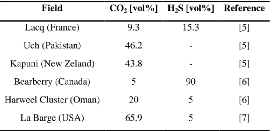
The global energy demand is expected to grow rapidly in the next twenty years. Primary energy consumption is expected to rise by 41% in 2035, with a great contribution coming from growing emerging economies. Among fossil fuels sources, natural gas demand is expected to have the most rapid growth [2]. Recent studies about geographical distribution of remaining discovered gas reserves have demonstrated that 40% of the actual remaining natural gas reserves are sour and/or with high carbon dioxide content [3-4]. Carbon dioxide content can vary between 15 % and 70 % [4] and the hydrogen sulfide concentration can reach 15 % [5]. Some examples of real gas fields compositions are given in Table 1.
Table 1. H2S and CO2 contents in some natural gas fields
Field CO2 [vol%] H2S [vol%] Reference
Lacq (France) 9.3 15.3 [5]
Uch (Pakistan) 46.2 - [5]
Kapuni (New Zeland) 43.8 - [5]
Bearberry (Canada) 5 90 [6]
Harweel Cluster (Oman) 20 5 [6]
La Barge (USA) 65.9 5 [7]
Natural gas must be purified to commercial grade to be suitable for the market and for subsequent utilization. Several techniques are available for the upgrading of natural gas streams. Mostly physical absorption and chemical scrubbing with amine solutions have been widely applied for the purification of streams in the natural gas industry [8]. However, this latter technology is energy intensive, particularly when carbon dioxide content in the feed gas is high [9]. Typically, a limit value for the concentration of CO2, in the natural gas stream to be purified, that gives the trade-off between the purification by means of amine scrubbing and low-temperature processes is 20 mol% [10]. In this scenario, natural gas producers need new process solutions to allow the profitable exploitation of low quality hydrocarbon gas reserves, which, until some years ago, were not considered suitable for commercialization. The new process solutions for the natural gas upgrading must be able to remove carbon dioxide and hydrogen sulfide, together with other impurities, to meet commercial specification, while decreasing the overall production costs in comparison with more standard technologies [11].
Several technologies have been proposed in literature for the low-temperature purification of natural gas: the Rectisol process [12], the Ryan-Holmes process [13-15], the CFZTM process
[16-dual pressure distillation unit [21]. Other applications of low-temperature processes are available also for the biogas upgrading, particularly the antisublimation process [22] which operates around the atmospheric pressure. In all these low-temperature purification processes it is of paramount importance to properly assess the thermodynamic conditions at which a solid phase can appear.
To allow reliable process design and optimization, suitable thermodynamic models are needed. In the meantime experimental data are required to properly set up equations of state for phase equilibrium calculations. The development of accurate thermodynamic model is essential for the calculation of transport, heat and mass transfer properties. Since in low-temperature processes for natural gas upgrading a solid phase can be formed, experimental data are necessary to determine pressure, temperature and phase compositions of phase equilibria involving a solid phase, consisting mainly of CO2. In this way it is possible to properly set up a model to predict the conditions for solid formation and choose the optimal process operating parameters, depending on the adopted technology. Literature data for the binary CO2-CH4 [23-35], CO2-H2S [36-37] and CH4-H2S [38-39] system are available to define the PT, the Tx or the Ty diagrams for SLE, SVE or SLVE loci. On the contrary, experimental data for phase equilibria involving a solid phase in the CH4-CO2-H2S ternary system are few and almost only PT data [40-41].
The aim of this work is to provide experimental TPxy data for defining the maximum temperature at which SLVE exists for different compositions of the CH4-CO2-H2S system. A proper experimental procedure, based on a synthetic non-visual technique, has been designed to allow these measurements. The procedure has been validated against available experimental data for the SLV locus of the binary CH4-CO2 mixture and subsequently applied to the study of the SLV loci of the ternary system. The obtained experimental results have been used to tune the thermodynamic model parameters and the results have been applied to the validation of the
optimized process layout of the dual-pressure low-temperature distillation process [21]. A preliminary assessment of the profitability of the studied process solution, in comparison with more traditional MDEA units, has been carried out by defining a proper merit index function that describes the trade-off between the two technologies in terms of energy costs, depending on the geographic area where the gas reserve is located.
2. Apparatus
The equipment used in this study is similar to the one developed by Baba Ahmed and De Stefani [42-43] and used by Courtial et al. for GPA project 052 developed for solubility measurement of CO2 into liquid oxygen in static analytic mode [44]. For this study, the equipment and experimental procedure were modified. The experimental facility used in this work is presented into two configurations (Fig. 1): a first one (Fig. 1a) used for the determination of the SLV locus of the CH4-CO2 binary mixture and a second one (Fig. 1b) adapted to perform the same kind of experiments on the ternary CH4-CO2-H2S system. The binary mixture has been considered in order to design the experimental procedure and to test its reliability against the literature available experimental data. The equilibrium cell is heated by means of an electric resistance, regulated by a Fuji electric PXR PID temperature controller. The cell is inserted in a liquid nitrogen cryostat. The mixing in the cell is provided by means of a magnetic stirrer. A 16 MPa PTX611 Druck pressure transducer is used to measure the internal pressure and two platinum probes are used to measure the temperatures in the upper and lower part of the cell. Capillary samplers (ROLSITM, Armines’ Patent) are used for sampling the mixture that is sent through a temperature-controlled transfer line to the gas chromatograph for the composition analysis. The samplers’ capillaries and the pressure transducer tube are insulated and heated by a
they are exposed to the nitrogen vapor from the cryostat. The pressure in the feed line is measured by means of a 20 MPa PTX611 Druck pressure transducer. In the configuration used for the ternary system investigation, two gas reservoirs have been used to charge the methane/carbon dioxide mixture and the hydrogen sulfide. The purge system is equipped with a vacuum pump. For experiments involving H2S, a nitrogen line has been installed to clean the equipment and the purge line is connected to a column containing a saturated solution of NaOH and provided with a magnetic stirrer. The acquisition system and the gas chromatograph are connected to a computer for data collection. The gas chromatograph is a Perichrom PR 2100 type and the column is a Porapak Q, 80/100 mesh, 1/8” external diameter and 2 mm internal diameter made in Silcosteel. The composition is determined by means of the analysis of samples using a carefully calibrated Thermal Conductivity Detector (TCD).
Figure 1. Flow diagram of the equipment used for a) TPxy solid apparition
measurements for the CH4-CO2 system and b) TPxy solid apparition measurements for the CH4-CO2-H2S system.
a) b) Liquid Nitrogen (LN2) LN2 CO2/CH 4 V 1 V 6 Vacuum pump V 3 V 2 Cryostat V 5 V 4 Temperature probes Gas chromatograph Acquisition 20 MPa Transducer 16 MPa transducer E C V 10 RolsiTM samplers CO2/CH4 reservoir Purge H2S V 8 H2S reservoir 7 V N2 purge V 9 NaOH Liquid Nitrogen (LN2) LN2 CH4 V 1 V 6 Vacuum pump V 3 V 2 Cryostat V 5 V 4 Temperature probes Gas chromatograph Acquisition 20 MPa Transducer 16 MPa transducer E C V 8 RolsiTM samplers CO2 Purge
3. Materials
Methane (CAS: 74-82-8) has been supplied by Messer, with a purity of 99.995 vol%. Carbon dioxide (CAS: 124-38-9) and hydrogen sulfide (CAS: 7783-6-4) have been supplied by Air Liquide, with a purity of 99.995 and 99.5 vol% respectively. For the experiments with the ternary mixture, two gas cylinders of a binary CH4-CO2 mixture have been used to keep constant the ratio between the number of moles of methane and carbon dioxide in the global composition at different mol% of hydrogen sulfide. The supplier of these cylinders is Air Liquide and the content of carbon dioxide is 70 and 40 mol% (as specified by the supplier) at 41 and 65 bar respectively.
4. Calibrations
The 16 MPa PTX611 Druck pressure transducer has been calibrated using a GE PACE5000 automated pressure indicator as reference. The pressure range used for calibration is 1-67 bar (calibration uncertainty u(P) = 0.1 kPa). The temperature sensors have been calibrated for reproducing the triple point [45] of CO2, N2O and R134a, to cover all the temperature range used for SLV measurement. The temperature range used from calibration is 169.85 K-216.59 K (calibration uncertainty u(T) = 0.015 K). The composition analysis has been carried out using a TCD to determine the composition of both liquid and vapor phases. The TCD has been calibrated correlating the peak surface of the output signal to the known amount of moles supplied to the injector through an Evol XR electronic automated syringe. The maximum calibration uncertainties for the vapor phase mole fractions are u(y, k = 2): 0.011 for CH4, 0.011 for CO2 and 0.009 for H2S and maximum calibration uncertainties for the measurements of the liquid phase mole fractions are u(x, k = 2): 0.009 for CH4, 0.018 for CO2 and 0.017 for H2S.
5. Experimental procedures
Firstly the equilibrium cell is loaded to obtain a desired global composition. The magnetic stirrer is turned on to avoid diffusivity effect. Once the equilibrium cell is loaded, the cryostat is filled with liquid nitrogen for the half of its volume, to avoid the contact between the metallic part of the equipment and the liquid nitrogen. The temperature of the cell is decreased 5 °C to 10 °C lower than the estimated triple point of the mixture.
During the cooling step, when solid CO2 starts to form, a change in the slope of the pressure vs. temperature in the cell can be noticed. Once the set temperature is achieved and system temperature and pressure are stable, the system is heated up. The regulation can be difficult due to the high temperature difference between the cell and the boiling liquid nitrogen in the cryostat. The heating rate plays a significant role in the determination of the triple point where the solid decomposition occurs. High heating rates take the system to be overheated, with a consequent shift in the effective triple point. Moreover dynamic effects during heating may occur. In this way a step procedure is preferable, since it lets the system to evolve through equilibrium conditions. The number of steps must be properly selected to allow the triple point calculation. In general it is a good practice to select a 10 °C range across the desired triple point and perform steps every 1 °C. Stable conditions for the system at each step must be assured. Every ramp lasts 30 min and each temperature soak is maintained for 1 h. In this way also the heating rate during each ramp is low and dynamic effects are minimized during temperature step changes. This procedure is equal to a slow heating (Fig. 2), but it is more controllable since, under dynamic conditions, the slow heating can be achieved only when the liquid nitrogen level in the cryostat is high. The sensitivity of the system to the dynamics of the boiling liquid nitrogen is high. High levels of liquid nitrogen
allow slow heating, but, as the level decreases, it is not possible to properly control the heating rate anymore.
Figure 2. a) Definition of the experimental procedure and b) example of triple point
calculation from PT data.
Collected temperatures and pressures in the cell are used to determine the equilibrium temperature and pressure on each soak. The temperature considered is the average between the temperatures measured on the top and on the bottom of the cell. The average value of temperature and pressure are reported on a PT diagram and two linear regressions are performed across the slope change in the PT trend. The triple point is then calculated as the intersection between the two lines (Fig. 2b). Once determined, the temperature is brought down, close to the triple point (typically 0.5 °C higher to avoid possible solid formation). Composition analysis can be performed once the system reaches stable conditions and temperature and pressure are close to the triple point.
The repeatability of the measurements and the rigorous check of the system effective equilibrium conditions have been checked by performing different sampling campaigns (at stable temperature
and pressure) for both the liquid and vapor phases composition analysis for the same equilibrium point several times and at different periods during the day.
For the loading of the ternary mixture in the cell, first H2S is loaded or directly into the cell at a pressure lower than the vapor pressure at atmospheric conditions, or, if necessary, by means of the H2S reservoir. The number of added moles can be calculated and so, knowing the pressure of the binary CO2-CH4 gas cylinders, the mixture reservoir volume and the ambient temperature, the correct number of moles of the binary mixture can be added in the cell to obtain per each cylinder four points at 20 mol%, 15 mol%, 10 mol% and 5 mol% of H2S in the global composition.
6. Experimental results
6.1. Validation of the procedure on the CH4-CO2 SLV locus
The obtained results for the TPxy measurements on the SLV locus of the CH4-CO2 mixture are reported in Figures 3-5. The estimated uncertainties (U), calculated according to the standards [46-47], for the measured solid dissociation points is U(T, k = 2) = 0.11 K and U(P, k = 2) = 10.6 kPa, while for the vapor and liquid phase compositions the maximum uncertainties have been presented in section 4. To test the reliability of the studied procedure, results obtained for the binary methane-carbon dioxide mixtures have been compared to literature data and to results obtained with the Yokozeki equation of state [48] with the parameters presented in reference [49]. The thermodynamic model will be discussed in the next section.
Figure 3. Comparison among literature data for the TP SLV locus of the CH4-CO2 mixture, experimental data obtained in this work and results obtained with the Yokozeki EoS [49] for SLV calculation.
Figure 4. Comparison among literature data for the Tx SLV locus of the CH4-CO2 mixture, experimental data obtained in this work and results obtained with the Yokozeki EoS [49] for SLV calculation.
Figure 5. Comparison among literature data for the Ty SLV locus of the CH4-CO2 mixture, experimental data obtained in this work and results obtained with the Yokozeki EoS [49] for SLV calculation.
The agreement among experimental data obtained in this work, literature available experimental data and model calculations is good for all the considered TP, Tx and Ty projections. Regarding the graph in Fig. 3, the first data series (TP SLV exp. This work) deals with the measured triple point, while the second data series (TPxy SLV exp. This work) refers to the experimental conditions used for composition analysis. The figure shows that the two series are almost overlapped, so that the composition has been measured at temperatures and pressures very close to the ones of the determined PT triple points. Moreover measurements close to the maximum of the SLV locus show that data by Davis et al. (1961) [24] are more reliable than the ones by Donnelly and Katz (1954) [23], which show a significant deviation from the main data trend.
6.2. Application of the procedure on the TPxy measurements on the SLV locus of the CH4-CO2-H2S system
shape of the SLV locus. The results of the experimental study for the ternary CH4-CO2-H2S mixtures are reported in Figures 6-8. The maximum uncertainty on the measured solid dissociation temperature is U(T, k = 2) = 0.19 K and the one for the pressure is U(P, k = 2) = 12.7 kPa. The maximum uncertainties of the vapor and liquid phase compositions have been discussed in section 4. Fig. 6 shows the temperatures and pressures at which the measurements have been carried out with respect to pure components and binary mixtures phase boundaries.
Figure 6. PT projections of the CH4-CO2, CO2-H2S and CH4-H2S systems with experimental TP measurements for the CH4-CO2-H2S system. : experimental data obtained in this work; : SLV locus of the binary CH4-CO2 system; : SLV and SSL loci of the binary CO2-H2S system; : SLV, VLL, SLL, SSL and low-temperature critical line of the binary CH4-H2S system; : PT diagram of pure CH4; : PT diagram of pure CO2; : PT diagram of pure H2S.
Figure 7. Phase equilibrium for the CH4+CO2+H2S system. The graphs from a) to d) show the evolution of the phase diagram when progressive amounts of H2S are added to a mixture of CH4+CO2 with a mole ratio of about 0.4/0.6. : experimental tie line for the ternary CH4-CO2-H2S mixture; : global composition and —: model results. From a) to d) the H2S molar fraction in the global composition is about: 0.20, 0.15, 0.10 and 0.05 respectively. SCO2+V SCO2 SCO2+L+V SCO2+L L L+V V T=202.85 K P=4.3212 MPa SCO2 SCO2+V SCO2+L+V SCO2+L L L+V V T=201.16 K P=3.6908 MPa SCO2 SCO2+V SCO2+L+V L L+V V T=200.07 K P=2.9979 MPa SCO2 V SCO2+V L L+V SCO2+L+V T=199.44 K P=2.4036 MPa
a)
b)
c)
d)
Figure 8. Phase equilibrium for the CH4+CO2+H2S system. The graphs from a) to d) show the evolution of the phase diagram when progressive amounts of H2S are added to a mixture of CH4+CO2 with a mole ratio of about 0.3/0.7. : experimental tie line for the ternary CH4-CO2-H2S mixture; : global composition and —: model results. From a) to d) the H2S molar fraction in the global composition is about: 0.20, 0.15, 0.10 and 0.05 respectively.
Results related to TPxy data have been discussed by comparison with the thermodynamic model results. In the system methane-hydrogen sulfide a quadruple point is present and, moreover, a liquid-liquid-vapor and a solid-liquid-liquid loci are present. This introduces the possibility of a quadruple point line, a solid-liquid-liquid and a liquid-liquid vapor surfaces in the system.
V L L+V SCO2+L+V SCO2+V SCO2 T=207.59 K P=3.4061 MPa V L L+V SCO2+L+V SCO2+V SCO2 T=207.28 K P=2.7555 MPa V L L+V SCO2+L+V SCO2+V SCO2 T=206.50 K P=1.9239 MPa V L L+V SCO2+L+V SCO2+V SCO2 T=204.61 K P=1.4599 MPa
a)
b)
c)
d)
Moreover, the binary carbon dioxide-hydrogen sulfide system presents a eutectic point in the solid liquid vapor locus. These complex behaviors may occur also in the ternary system.
The obtained experimental data falls in a region of T and P away from the one where complex phase behavior may occur. From the graphs (Fig. 7-8), it can be noticed that the measured points are really the triple points of the ternary mixture. For these points the phase diagram is quite simple.
7. Thermodynamic model
The thermodynamic model used to describe experimental data for both binary CH4-CO2 and ternary CH4-CO2-H2S mixtures is based on the Yokozeki EoS (2003) for SLV calculations [48-49] (Eq. 1). The model has been set up for this work according to the procedure described by Stringari et al. (2014) [49] for both pure compounds and binary mixtures of CH4-CO2, CO2-H2S and CH4-H2S.The detailed description of the model can be found in literature [49-50].
Calculations of phase equilibria are performed using a Fortran routine for the Gibbs free energy minimization. For the binary CH4-CO2 mixture the model has been already validated against experimental data [49-50]. Pure compound thermophysical properties have been taken from NIST (REFPROP 9) [45], while pure compound parameters for the EoS have been taken from literature for CO2 and CH4 [49], while for H2S they have been obtained by regression, according to [49], against auxiliary values (obtained using REFPROP 9 [45]) for the VLE, SLE and SVE of the pure compound. The considered objective function is:
𝐴𝐴𝐷% = 100 𝑁𝑃𝑇𝑒𝑞 𝑃𝑗 ,𝑒𝑞𝑐𝑎𝑙𝑐 − 𝑃𝑗 ,𝑒𝑞𝑒𝑥𝑝 𝑃𝑗 ,𝑒𝑞𝑒𝑥𝑝 𝑁𝑃𝑇𝑒𝑞 𝑗 =1 𝑒𝑞 = 𝑆𝑉𝐸, 𝑉𝐿𝐸, 𝑆𝐿𝐸 (1)
The values of the binary interaction parameters for the CH4-H2S and CO2-H2S mixtures have been obtained by regression considering literature available experimental data. For the CH4-H2S system VLE [38, 51-52], SLE [39] and LLE [52] experimental data have been considered , while for the binary CO2-H2S system SLVE experimental data [36] have been used for parameters regression. The agreement between model results and considered experimental data for the former binary system is good, while for the latter system a good representation of the liquidus curve and a less accurate representation of the solid-vapor curve have been obtained on the SLV locus. Due to the less accuracy in binary interaction parameters for the representation of the SLV locus of the CO2-H2S system, the eutectic point [36] is overestimated in terms of temperature and pressure. In this way, its solid-solid-liquid line (Fig. 6), which starts from the eutectic point, is shifted at higher temperatures. For the process validation (see next section) this is not a problem, since the overestimation of the CO2-H2S eutectic point, in terms of temperature and pressure, let the model to be more conservative. The binary interaction parameters have been obtained by minimizing the following objective function:
𝑓𝑜𝑏𝑗 = 1
𝑁𝑃𝑇 𝑥𝑗𝑐𝑎𝑙𝑐 − 𝑥𝑗𝑒𝑥𝑝 𝑁𝑃𝑇
𝑗 =1
(2)
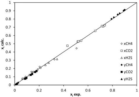
where x is the mole fraction of the lighter compound of the binary mixture in each phase at equilibrium. The agreement between the experimental data and the model results for the ternary system is shown in Figure 9.
Figure 9. Model performances (Yokozeki, 2003 with binary interaction parameters
obtained in this work) for the prediction of SLV composition for the ternary CH4- CO2-H2S mixture.
The agreement between calculated and experimental data is quite good and values of AAD%s are less than 7%.
8. Application to the low-temperature distillation process
The new process for the low-temperature purification of natural gas has been studied at Politecnico di Milano [21]. The process is based on a dual pressure (approximately 40/50 bar) low-temperature distillation operation, designed to bypass the SLV locus of the CH4-CO2 binary mixture through a proper thermodynamic pathway. In this work an optimized process layout has been taken into account (Fig. 10).
0 0.1 0.2 0.3 0.4 0.5 0.6 0.7 0.8 0.9 1 0 0.2 0.4 0.6 0.8 1 xi ca lc. xiexp. xCH4 xCO2 xH2S yCH4 yCO2 yH2S
Figure 10. Process flow diagram for the new low-temperature distillation process
[21].
The gas stream to be purified (1) is fed to the high pressure (HP) section T-1 at its dew point; in this first part of the distillation unit, the natural gas feed is separated into two streams: a bottom one (2) with a high CO2 content and a top product flow (3) rich in methane. The top product stream (3) from the HP section is split into two streams: the first one (3h) is heated (4h) and expanded (5h) to the low pressure (LP) section pressure; the second one (3c) is cooled (4c) so that after expansion it is at its bubble point at 40 bar (5c). The superheated gas stream is fed at the bottom of the LP section while the liquid feed is sent few theoretical trays above the bottom of the LP section. In the LP distillation section a top product methane gas stream at commercial grade is obtained, while the bottom liquid stream (6) rich in methane is pumped back to the HP section (stream 7) to provide the reflux.
The rationale of the process to avoid the solid CO2 formation is the bypass of the maximum of the SLV locus of the methane-carbon dioxide system.
In the HP section the separation is limited by the critical point of the mixture, that does not allow to reach the commercial grade for the methane stream. So the mixture must be depressurized slightly under the critical pressure of pure methane, avoiding huge recompression costs. At 50 bar the SLE and the VLE surfaces are completely divided, thus no solidification during distillation operation may occur. Solidification inside distillation units can occur only at triple point. During the cooling at 50 bar of the split part of stream 3 (HP section top product) the SLE is never crossed, so the operation is performed without freezing of the mixture. On the other hand, stream 4c arrives at 40 bar without crossing the SLV locus during the expansion. The part of stream 3 that goes to the intermediate heat exchanger (stream 3h) cannot be fed to the LP section without superheating, otherwise the produced stream at 40 bar can form a solid phase in the solid-vapor region at 40 bar.
To avoid the frosting of carbon dioxide at the inlet of the LP section, the stream must be heated at 50 bar before expansion. The limiting condition to frosting is the dew point of stream 5h at 40 bar. For safety reasons, it is suggested to keep the temperature of this stream 5-6 K over its dew point at 40 bar, without forming a solid phase. In this way the presence of dry ice is avoided in all the parts of the process. From the top of the LP section, a methane stream at commercial specification is obtained, while the bottom liquid stream rich in methane is pumped back to 50 bar and sent to the top of the HP section few theoretical trays over the feed tray. To avoid the freezing at the outlet of the LP section, the CO2 content in this stream must be kept at about 8 mol%, so that the LP section of the distillation unit operates in the liquid-vapor region under the low-temperature triple point at 40 bar.
The process has been studied using the commercial process simulator Aspen Hysys® v7.3 [53]. The feed stream has a CO2 content from 5 to 65 mol% and a hydrogen sulfide content from 0 to 15 mol% per each value of the CO2 mole fraction. The methane content in the feed stream is the balance. The composition range has been defined in order to cover the largest possible field of real gas compositions, to better assess the performances of the proposed solution in different existing cases.
As process specifications, the methane content in the HP section bottom stream (2) has been fixed at 0.01 mol%, to enhance the hydrocarbon recovery of the process unit, while for the purity of the produced gas (stream 8) classical specifications for H2S and CO2 contents in pipeline-quality gas have been adopted [11, 54].
To show the potentiality of the thermodynamic study previously illustrated for the design and validation of low-temperature distillation process, the thermodynamic model validated against obtained and literature experimental data has been used to draw SLE lines for the ternary system at fixed contents of hydrogen sulfide in the global composition. Since under 50 bar solidification occurs at triple point and its simple graphical representation may be difficult for ternary systems, an alternative procedure has been adopted. Considering the slope of the SLE curves of pure compounds it is possible to notice that it is highly steep: small variations of temperature can lead to high variations of pressure. Moreover, the phase behavior of condensed phases is not strongly influenced by the pressure in the range of medium-low pressures. Therefore, to check the possible formation of a solid phase in the process involving ternary mixtures, the SLE diagram at 50 bar has been used, with a liquid phase having hydrogen sulfide contents from 0 up to 15 mol% as considered in the gas feed stream of the studied process. Column liquid phase composition profiles normalized on their H2S contents have been plotted against SLE curves (Fig. 11) to
check possible crosses with the solid-liquid equilibrium lines. It has to be pointed out that the hydrogen sulfide mole fraction varies, tray by tray, in the two sections of the distillation units.
Figure 11. SLE lines at 50 bar for the ternary CH4-CO2-H2S system and check of the possible formation of a solid phase in the process involving the ternary system.
Results show that no intersection between SLE lines and distillation curves occurs. Moreover, the process lines do not cross the SLE locus of pure CH4-CO2 system as well, remaining far away from freezing conditions in both the HP and LP sections. Moreover, the eutectic behavior of the system is highlighted. At high contents of hydrogen sulfide, the SLE lines become representative of a SLLE line (dashed).
The profiles along the LP section of the process are close to these lines, however the amount of H2S in the liquid phase in this section of the process is really small (since the biggest part of H2S
160 180 200 220 240 260 280 300 0 0.2 0.4 0.6 0.8 1 Te m p er atu re [ K ] xCH4 0% H2S 5 % H2S 10% H2S 15% H2S 5% CO2 5% H2S HP 5% CO2 5% H2S LP 65% CO2 5% H2S HP 65% CO2 5% H2S LP 5 %CO2 10% H2S HP 5 %CO2 10% H2S LP 65% CO2 10% H2S HP 65% CO2 10% H2S LP 5 % CO2 15% H2S HP 5% CO2 15% H2S LP 65% CO2 15% H2S HP 65% CO2 15% H2S LP
SLL
HP section LP section LP section HP sectionis removed in the HP section); indeed no liquid-liquid immiscibility occurs in this part of the process. No solid phase is formed in the presence of hydrogen sulfide in the process gas feed. It is possible to build a merit-index function to show the profitability of the low-temperature process respect to more traditional MDEA units [55]. The details of a preliminary techno-economic evaluation can be found elsewhere [56]. The comparison has been carried out in terms of energy expenses for the two processes, showing the relative trade-off between the two technologies depending on the geographic area where the gas reserve is located. The breakeven point is established depending on the ratio between the price of the fuel gas and the price of electricity (Fig. 12): fuel gas is used to produce steam for MDEA regenerator reboiler, while electric energy is consumed to drive the compressors of the refrigeration cycle for the low-temperature purification process.
Figure 12. Breakeven point loci obtained as functions of costs of gas and electricity,
and the acid gas contents in natural gas. Trade-off for different geographic areas is highlighted. 0 0,1 0,2 0,3 0,4 0,5 0,6 0,7 0,8 0,9 1 5 10 15 20 25 30 35 40 45 50 55 60 65 $f u el /$el ect ri ci ty CO2 %mol 0% H2S 5% H2S 10% H2S 15% H2S
Saudi Arabia
Europe
USA
Conclusions
In this work experimental TPxy data have been obtained for defining the maximum temperature at which SLVE exists for different compositions of the CH4-CO2-H2S system. A proper experimental methodology, based on a synthetic non-visual technique, has been developed. The procedure has been validated performing TPxy measurements on the SLV locus of the binary CH4-CO2 mixture and comparing the obtained results with literature available data. The obtained experimental results have been used to properly check the reliability of the Yokozeki SLV EoS applied to ternary mixtures of CH4-CO2 and H2S, used in this work for the thermodynamic modeling. The model has been used to design phase diagrams and SLE lines for the ternary system. The obtained results have been applied for the thermodynamic validation of a new low-temperature distillation process for the purification of natural gas. This work highlights the importance and the effectiveness of the thermodynamic work applied to process design and simulation and the potential of coupling the two approaches to solve industrial problems: the obtained experimental data have been of paramount importance to properly investigate the reliability and the performances of the Yokozeki SLV EoS applied to mixtures of interest for natural gas. Complex phase behaviors, like the presence of a eutectic point in the SLE lines, have been shown. Improvements made on the thermodynamic model of these systems have been fundamental to properly investigate the possibility of solid phase formations in a low-temperature distillation process for the purification of natural gas, allowing the rigorous check on freeze-out problems in the system. The comparison of column liquid phase composition profiles, calculated from process simulations, and the obtained SLE lines has shown that no solid phase is formed at
grade, natural gas streams having different amounts of acid gases without incurring in freeze-out problems. The process, in this way, results validated from a thermodynamic point of view and functional for its aim. Moreover, the economic profitability of the validated process in comparison with more traditional MDEA units has been preliminarily assessed in terms of energy OPEX, considering different possible geographic areas where the gas reserve can be located. However, other compounds are present typically in natural gas streams (C2, C3, C4 and C5+ hydrocarbons, aromatics, mercaptans, traces of hydrates inhibitors such as methanol or MEG) and the presence of these substances may influences the phase behavior of natural gas mixtures. As future developments for this work, new experimental investigations will be done to study the effect of the mentioned compounds on the ternary system object of this work, in order to better understand the complex phase behavior of mixtures of interest for the natural gas industry in a large region of temperatures and pressures and to better investigate the proposed process solution for the purification of real gas streams, considering all the components of a typical natural gas feed.
Literature cited
[1] BP, 2012. BP Energy Outlook 2030. www.bp.com (Accessed April 2013). [2] BP, 2014. BP Energy Outlook 2035. www.bp.com (Accessed September 2014).
[3] Carrol J. J., Foster J., 2008. New Challenges & Solutions in Designing Large Sour Gas Projects.
www.fwc.com (Accessed September 2014).
[4] Burgers W. F. J., Northrop P. S., Kheshgi H. S., Valencia J. A. 2011. Worldwide Development Potential for Sour Gas. Energy Proced. 4, 2178-2184.
[5] Rojey A., Jaffaret C., Cornot-Gandolphe S., Durand B., Jullian S., Valais M., 1994. Natural Gas Production Processing Transport. Éditions Technip, Paris.
[6] Scherbinin A., 2012. Shell Experience in Sour Gas Fields. Turkmenistan Gas Conference, Avaza, May 2012, Turkmenistan.
[7] Parker M. E., Northrop P. S., Valencia J. A., Foglesong R. E., Duncan W. T., 2011. CO2 Management at ExxonMobil’s LaBarge Field, Wyoming, USA. Energy Proced. 4, 5455-5470. [8] Kohl A. L., Nielsen R. B., 1997. Gas Purification, fifth ed.; Gulf Publishing Company: Houston, TX.
[9] Swattanapong R., Aroonwilas A., Veawab A., 2005. Behavior of Reboiler Heat Duty for CO2 Capture Plants Using Regenerable Single and Blended Alkanolamines. Ind. Eng. Chem. Res. 44, 4465-4473.
[10] Lallemand F., Lecomte F., Streicher C., 2005. Highly Sour Gas Processing: H2S Bulk Removal With the Sprex Process. Int. Petr. Tech. Conf., 21-23 Nov. 2005, Doha, Qatar.
[11] Northrop P. S., Valencia J. A., 2009. The CFZTM process: A Cryogenic Method for Handling High-CO2 and H2S Gas Reserves and Facilitating Geosequestration of CO2 and Acid Gases. Energy Proc. 1, 171-177.
[12] Hochgesand G., 1970. Rectisol and Purisol. European and Japanese Chemical Industries Symposium 62(7), 37-43.
[13] Holmes A.S., Price B.C., Ryan J.M., Styring R.E., 1983. Pilot tests prove out cryogenic acid–gas/hydrocarbon separation processes. Oil Gas J. 27, 85–91.
[14] Holmes A.S., Ryan J.M., 1982. Cryogenic distillative separation of acid gases from methane. US Patent 4318723.
[16] Haut R.C., Denton R.D., Thomas E.R., 1989. Development and application of the controlled-freeze-zone process. SPE Prod. Eng., 265–271.
[17] Valencia J.A., Denton R.D., 1985. Method and apparatus for separating carbon dioxide and other acid gases from methane by the use of distillation and a controlled freeze zone. US Patent 4533372.
[18] Valencia J.A., Victory D.J., 1990. Method and apparatus for cryogenic separation of carbon dioxide and other acid gases from methane. US Patent 4923493.
[19] Valencia J.A., Victory D.J., 1993. Bubble cap tray for melting solids and method for using same. US Patent 5265428.
[20] Amin R., Jackson A., Kennaird T., 2005. The Cryocell: an Advanced Gas-Sweetening Technology. Int. Petr. Tech. Conf., 21-23 Nov. 2005, Doha, Qatar.
[21] Pellegrini L.A., 2014. Process for the removal of CO2 from acid gas. WO Patent 2014/054945A2.
[22] EReIE CRYO-PUR Project. http://www.ereie-sas.fr/pole-biogaz-cryo-pur/ (accessed February 10, 2015).
[23] Donnelly H. G., Katz D. L., 1954. Phase Equilibria in the Carbon Dioxide–Methane System. Ind. Eng. Chem. 46, 511–517.
[24] Davis J. A., Rodewald N., Kurata, F., 1962. Solid–Liquid–Vapor Phase Behavior of the Methane–Carbon Dioxide System. AIChE J. 8, 537–539.
[25] Im U. K., Kurata F., 1971. Phase Equilibrium of Carbon Dioxide and Light Paraffins in Presence of Solid Carbon Dioxide. J. Chem. Eng. Data 16(3), 295-299).
[26] Shen T., Gao T., Lin W., Gu a., 2012. Determination of CO2 Solubility in Saturated Liquid CH4 + N2 and CH4 + C2H6 Mixtures above Atmospheric Pressure. J. Chem. Eng. Data 57, 2296-2303.
[27] Cheung H., Zander E. H., 1968. Solubility of Carbon Dioxide and Hydrogen Sulfide in Liquid Hydrocarbons at Cryogenic Temperatures. Chem. Eng. Symp. Ser. 64(88), 34-43.
[28] Boyle G. J., Shell Res. LTD., 1987. In Knapp H., Teller M., Langhorst R. Solid−Liquid Equilibrium Data Collection; Vol. VIII, part 1, Chemistry Data Series, Volume VIII, part 1; Dechema: Frankfurt, Germany, 1987.
[29] Brewer J., Kurata F., 1958. Freezing Points of Binary Mixtures of Methane. AIChE J. 4(31), 317-318.
[30] Sterner C. J., 1961. Phase Equilibria in the CO2−Methane Systems. Adv. Cryog. Eng. 6, 467−474.
[31] Knapp H., Teller M., Langhorst R., 1987. Solid−Liquid Equilibrium Data Collection; Vol. VIII, part 1, Chemistry Data Series, Volume VIII, part 1; Dechema: Frankfurt, Germany, 1987. [32] Streich M., 1970 N2 Removal from Natural Gas. Hydrocarbon Process. 49, 86−88. [33] Voss G., 1975. Ph.D. Thesis, Technical University of Berlin, Berlin, Germany.
[34] Brady C. J., Cunningham J. R., Wilson G. M., 1982. Water-Hydrocarbon Liquid-Liquid-Vapor Equilibrium Measurements in 530 Degrees F, GPA Research Report. RR-62. Gas Processors Association, Tulsa, OK.
[35] Sparks K.A., Sloan E.D., 1983. Water Content of NGL in Presence of Hydrates, GPA Research Report RR-71. Gas Processors Association, Tulsa, OK.
[36] Sobocinski D. P., Kurata F., 1959. Heterogeneous Phase-Equilibria of the Hydrogen Sulfide-Carbon Dioxide System. AIChE J. 5 (4), 545-551.
[37] Chapoy A., Coquelet C., Liu H., Valz A., Tohidi B., 2013. Vapour–Liquid Equilibrium Data for the Hydrogen Sulphide (H2S) + Carbon Dioxide (CO2) System at Temperatures from 258 to 313 K. Fluid Phase Equilib. 356, 223-228.
[38] Kohn J. P., Kurata F., 1958. Heterogeneous Phase Equilibria of the Methane-Hydrogen Sulfide System. AIChE J. 4(2), 211-217.
[39] Cheung H., Zander E. H., 1968. Solubility of Carbon Dioxide and Hydrogen Sulfide in Liquid Hydrocarbons at Cryogenic Temperatures. Chem. Eng. Symp. Ser. 64(88), 34-43.
[40] Robinson D. B., Ng H. J., Leu A. D., 1981. The Behavior of CH4-CO2-H2S Mixtures at Sub-ambient Temperatures. GPA Research Report, No. 47. Tulsa, OK, USA.
[41] Théveneau P., Coquelet C., Richon D., 2007. Recherche de la température de formation d’une phase solide pour cinq systèmes méthane - dioxyde de carbone - sulfure d’hydrogène, report CEP/TEP/2007-01, 2007, confidential.
[42] De Stefani V., Baba Ahmed A., Richon D., 2003. Experimental Determination of Carbon Dioxide and Nitrous Oxide Co- Solubility in Liquid Oxygen. Fluid Phase Equil. 207(1-2), 131-142.
[43] De Stefani V., Baba Ahmed A., Valtz A., Meneses D., Richon D., 2002. Solubility Measurements for Carbon Dioxide and Nitrous Oxide in Liquid Oxygen at Temperatures Down to 90 K. Fluid Phase Equil. 200(1), 19-30.
[44] Courtial X., Booneart E., Valtz A., Theveneau P, Stringari P., Coquelet C., 2013. Research Report 219 - Methanol Distribution (as a contaminant) in Fractionation Products and Freeze Out Boundaries, GPA Research Report, No. 219. Tulsa, OK, USA, 2013.
[45] Huber M.L., McLinden M.O., Lemmon E.W., 2007. NIST Standard Reference Database 23, Reference Fluid Thermodynamic and Transport Properties-REFPROP, Version 9.0, National Institute of Standards and Technology, Standard Reference Data Program, Gaithersburg, 2013. [46] Taylor B.N., Kuyatt C.E., 1994. Guidelines for evaluating and expressing the uncertainty of NIST measurement results, Technical report, National Institute of Standards and Technology, Gaithersburg, MD.
[47] Stringari P., Valtz A., Chapoy A., 2014. Study OF Factors Influencing Equilibrium and Uncertainty in Isochoric Hydrate Dissociation Measurements. Proceedings of the 8th International Conference on Gas Hydrates (ICGH8-2014), Beijing, China, 28 July - 1 August, 2014.
[48] Yokozeki A., 2003. Analytical Equation of State for Solid-Liquid-Vapor Phases. Int. J. Thermophys. 24(3), 589-619.
[49] Stringari P., Campestrini M., Coquelet C., Arpentinier P., 2014. An Equation of State for Solid-Liquid-Vapor Equilibrium Applied to Gas Processing and Natural Gas Liquefaction. Fluid Phase Equil. 362, 258-267.
[50] Riva M., Campestrini M., Toubassy J., Clodic D., Stringari P., 2014. Solid−Liquid−Vapor Equilibrium Models for Cryogenic Biogas Upgrading. Ind. Eng. Chem. Res. 53(44), 17506-17514.
[51] Reamer H. H., Sage B. H., Lacey W. N., 1951. Phase Equilibria in Hydrocarbon Systems. Lacey, Ind. Eng. Chem. 43(4), 976-981.
[52] Coquelet C., Valtz A., Stringari P., Popovic M., Richon D., Mougin P., 2014. Phase Equilibrium Data for the Hydrogen Sulphide + Methane System at Temperatures from 186 to 313 K and Pressures up to About 14 MPa. Fluid Phase Equilib. 383, 94-99.
[53] AspenTech, 2010. Aspen HYSYS®. AspenTech, Burlington, MA, USA.
[54] Mokhatab S., Poe W. A., Speight J. G., 2006. Handbook of Natural Gas Transmission and Processing. Gulf Professional Publishing, Burlington, MA, USA.
[55] Pellegrini L.A., Langè S., Mikus O., Picutti B., Vergani P., Franzoni G., Lo Savio M., Brignoli F., 2015. A New Cryogenic Technology for Natural Gas Sweetening. SOGAT 2015 Conference Proceedings, March 22-26, Abu Dhabi, UAE.
[56] Langè S., 2015. Purification of Natural Gas by means of a New Low Temperature Distillation Process. PhD Thesis, Politecnico di Milano, March 12 2015, Milano, Italy.


![Figure 10. Process flow diagram for the new low-temperature distillation process [21]](https://thumb-eu.123doks.com/thumbv2/123doknet/11630413.305804/21.918.332.581.108.461/figure-process-flow-diagram-new-temperature-distillation-process.webp)
