HAL Id: hal-01185737
https://hal.inria.fr/hal-01185737
Submitted on 21 Aug 2015
HAL is a multi-disciplinary open access
archive for the deposit and dissemination of
sci-entific research documents, whether they are
pub-lished or not. The documents may come from
teaching and research institutions in France or
abroad, or from public or private research centers.
L’archive ouverte pluridisciplinaire HAL, est
destinée au dépôt et à la diffusion de documents
scientifiques de niveau recherche, publiés ou non,
émanant des établissements d’enseignement et de
recherche français ou étrangers, des laboratoires
publics ou privés.
Designing Applications for Heterogeneous Many-Core
Architectures with the FlexTiles Platform
Benedikt Janßen, Fynn Schwiegelshohn, Martijn Koedam, François Duhem,
Leonard Masing, Stephan Werner, Christophe Huriaux, Antoine Courtay,
Emilie Wheatley, Kees Goossens, et al.
To cite this version:
Benedikt Janßen, Fynn Schwiegelshohn, Martijn Koedam, François Duhem, Leonard Masing, et al..
Designing Applications for Heterogeneous Many-Core Architectures with the FlexTiles Platform.
SAMOS - 15th International Conference on Embedded Computer Systems: Architectures,
Model-ing, and Simulation, IEEE, Jul 2015, Samos Island, Greece. pp.9. �hal-01185737�
Designing Applications for Heterogeneous
Many-Core Architectures with the FlexTiles Platform
Benedikt Janßen
†, Fynn Schwiegelshohn
†, Martijn Koedam
‡, François Duhem
∆, Leonard Masing
*, Stephan Werner
*,
Christophe Huriaux
§, Antoine Courtay
§, Emilie Wheatley
*, Kees Goossens
‡, Fabrice Lemonnier
∆, Philippe Millet
∆,
Jürgen Becker
*, Olivier Sentieys
¶, Michael Hübner
††Ruhr-University Bochum, ‡Eindhoven University of Technology, *Karlsruhe Institute of Technology, ∆Thales Research and
Technology, §University of Rennes 1 — IRISA, ¶Inria, *Sundance Multiprocessor Technology
{Benedikt.Janssen, Fynn.Schwiegelshohn, Michael.Huebner}@rub.de, {M.L.P.J.Koedam, K.G.W.Goossens}@tue.nl, {Leonard.Masing, Stephan.Werner, Becker}@kit.edu, emilie.w@sundance.com, {francois.duhem, fabrice.lemonnier, philippe.millet}@thalesgroup.com
Abstract—The FlexTiles Platform has been developed within
a Seventh Framework Programme project which is co-funded by the European Union with ten participants of five countries. It aims to create a self-adaptive heterogeneous many-core architecture which is able to dynamically manage load balancing, power consumption and faulty modules. Its focus is to make the architecture efficient and to keep programming effort low. Therefore, the concept contains a dedicated automated tool-flow for creating both the hardware and the software, a simulation platform that can execute the same binaries as the FPGA prototype and a virtualization layer to manage the final heterogeneous many-core architecture for run-time adaptability. With this approach software development productivity can be increased and thus, the time-to-market and development costs can be decreased. In this paper we present the FlexTiles Development Platform with a many-core architecture demonstration. The steps to implement, validate and integrate two use-cases are discussed.
Keywords— Seventh Framework Programme, self-adaptive, heterogeneous, many-core, high efficiency, low development effort
I. INTRODUCTION
The FlexTiles project aims to tackle the challenges of
designing and programming energy-efficient and
heterogeneous many-core architectures with self-adaptation features. By solving the challenges the accessibility of these platforms will be raised. To achieve this goal the FlexTiles project developed a hardware architecture, which can be emulated on the FlexTiles Development Board (FDB), as well as simulated within the Open Virtual Platforms simulator.
The FlexTiles hardware architecture is a heterogeneous many-core system which consists of General Purpose
Processors (GPP) and dedicated accelerators. These
components are connected over a Network-on-Chip (NoC). The components of this system are structured into several tiles. A tile is a logical group of platform components. The simplest tile contains just a single GPP. It is called a GPP tile.
Figure 1 shows an abstract view on the FlexTiles architecture and visualizes the tile concept. The platform features an embedded FPGA (eFPGA), which is meant to be 3D stacked on top of a heterogeneous many-core layer. The eFPGA hardware architecture is specifically designed for the FlexTiles hardware platform.
Furthermore, the associated tool-flow has been developed to create, simulate and implement the architecture. Besides the hardware, the tool-flow also allows to create the corresponding software part. Hence the FlexTiles project enables the automatic integration of a target application into an execution platform and an application bundle. After the integration, each executed application get its own virtual representation of the platform which is managed by a virtualization layer. Through the abstraction of the underlying hardware, self-adaptation techniques can be applied without impeding application execution.
In this paper we are presenting the basics of the FlexTiles Development Platform (FDP) in section I. Section II explains the design flow for applications with the FDP in general. For the evaluation of the FDP described in section III, we implemented two applications. The SUSAN application was the first application to be implemented and is used to evaluate the tool-flow and show the features of the platform. Its integration is explained in section III.A. The number plate detection is an industrial application which was ported to the many-core system with the FDP. The aspects of its integration are described in section III.B. Finally, section IV concludes this paper.
II. STATE OF THE ART
Apart from FlexTiles the authors of [1] tackeled the challenges of the design space exploration for heterogeneous many-cores with a high-level synthesis approach. They propose a hardware architecture consisting of several GPPs linked to hardware accelerators through an interconnect. The application integration is done semi-automatic and hardware accelerated code segments needed to be chosen manually. Similarly, the LegUp project [2] aims to automize the application integration into a heterogenous platform. The
tool-NoC
GPP Node GPP Node DDR Node IO Node
NI NI NI NI NI NI NI AI AI AI ReConfCtrl NI NI eFPGA Hw Acc Hw Acc ... ... GPP Node DSP Tiles
Figure 1: FlexTiles Architecture
flow is highly advanced and supports a partitioning of the code. However, it does not target many-core systems. An approach
from the EU-project MORPHEUS [3], targeted a
heterogeneous multicore plattform where a ARM9 processor together with 3 different hardware-reconfigurable cores was brought together on a system on chip (SoC). The MORPHEUS SoC can be seen as prototype of one tile in the FlexTiles project. Additionally, as done in FlexTiles, a NoC was used to realize a efficient communication infrasctructure (see [4]) on chip. In [5] a many-core platform is proposed which is composed of several computing cluters. The management is done by virtualization layer which gathers status information of the system in order to dynamically adapt it. Unlike FlexTiles this project is not targeting integrated embdeeded systems. Schor, et al. present the EURETILE approach in [6]. Within this project, a tool-flow was developed targeting a heterogeneous many-core tile based platform. In contrast to FlexTiles the tiles are more complex, consiting of a network processor, several GPPs and dedicated accelerators.
I. BACKGROUND
A. Software Architecture Overview
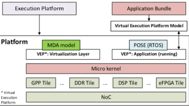
The overall FlexTiles run-time environment is depicted in Figure 2. It consists of the hardware architecture which is described in the next section I.B and the corresponding software modules and methods. The software architecture is based on the CoMiK microkernel [7], which manages the executed tasks and the tile memory, as well as a first level scheduling. On top of it, additional services are provided by the other tile components, such as the cyclo-static data flow real-time operating system POSE and the resource managers. POSE implements the model of computation and the second level scheduler.
The FlexTiles platform enables a point-to-point
communication between tasks. Therefore, the C-HEAP protocol [8] is used, which provides a circular buffer as communication FIFO between the producer and the consumer. The synchronisation is done via read and write counters.
The resource managers control the tile’s local resources. These resources include CPU time, DMA controller, memory and communication FIFO memory. The resource manager also provides information about the current processor state, such as the current workload, instruction and data memory utilization and temperature. Moreover, it monitors the executed applications and tasks in order to provide information about
application workload, application memory utilization, task execution time, worst case execution time and communication FIFO usage. Global resources are associated to another resource manager, running on a GPP without any associated accelerator (GPP tile), such as the NoC, the DSP, and the eFPGA.
In order to manage the resources of the GPP peripherals, a DSP and eFPGA resource manager client have been implemented. The eFPGA’s resources are managed by a single client which tracks the usage and performs the configuration of the programmable logic. The DSP resource manager monitors the availability of the DSP, as it is allocated to a single task, and provides run-time information such as workload, clock frequency, voltage and temperature. On top of the base system a virtualization layer has been implemented which enables the management of the executed applications without interfering with their execution. It is described within the next section I.A.1). The used adaptation scheme is presented in section I.A.2).
1) Virtualization Layer
The FlexTiles software architecture introduces a
virtualization layer to support the self-adaptation, described in section I.A.2), being transparent to the executed applications. Each application is executed within its own virtual execution platform, which isolates it from other executed applications.
This virtualization layer has a local and a global component. The local component is executed as a privileged application which is executed within its time-slots of the tile’s processor. In contrast to unprivileged applications it can access the resource managers and thus retrieve information about the current tile state, as described earlier in this section. Moreover, it can influence the tile’s resource allocation through the resource managers API and control the execution on each tile.
The global part of the virtualization layer makes decisions at run-time which then are executed by the local component. Here, information from all the tiles is aggregated and analyzed. Decisions are distributed back to the local component on each tile which then enforces the changes. Furthermore, the virtualization layer is able to check for new application images available in the shared memory. Such an image is parsed and a respective virtual platform created and loaded onto the processing tiles.
2) Self-Adaptation
The dynamic execution of applications and utilization of resources also calls for dynamicty of the requirements during run-time. By enabling self-adaptation the system is able to optimize and refine resource utilization and deal with application requirements and run-time constraints, such as power consumption. Action Monitoring Diagnosis Re so u rce M an ag e r DMA DDR ... NoC
Figure 3: FlexTiles virtual execution platform
Platform
NoC
GPP Tile DDR Tile DSP Tile eFPGA Tile
Micro kernel
Application Bundle
... ... ...
VEP*: Virtualization Layer MDA model
Virtual Execution Platform Model
VEP*: Application (running) POSE (RTOS)
* Virtual Execution Platform
Figure 2: FlexTiles Run-time environment
The MDA (Monitoring, Diagnosis, Action) model [9] is used within the FlexTiles project to adapt the platform to its current state. The three phases of this model are presented in Figure 3. On each tile a number of metrics, both internal and external through sensors, are monitored and updated regularly. The Diagnosis relies on a constraint table for each application, which defines scenario switch conditions and general requirements like e.g. throughput. Towards this purpose, the virtualization layer offers an interface to the applications through which the requirements can be registered. For missing entries, default values are selected. Based on the monitoring information and the constraint tables, actions are decided and enforced by the local part of the virtualization layer. These actions may include increasing the time slots of the scheduler to increase throughput, moving tasks between different tiles to enhance load-balancing and heat dissipation and replacing scenarios to adapt an applications execution to changing environmental situations. In order to self-adapt continuously, the phases of the MDA model are performed in a sequential and cyclic manner.
B. Hardware Architecture Overview
A brief description to the FlexTiles architecture has been given in section I together with the overview in Figure 1. In this section, a more detailed view on the architecture, which is used for the simulation and the emulation of the two implemented applications, is presented. The emulator of the FDP is based on the FDB. It consists of two Xilinx Virtex 6 FPGAs, 256MByte DDR-SDRAM and supports various connection standards. The FPGAs are linked via two physical channels. These connections are used to enable the utilization of both FPGAs for the platform described in subsection 1).
In order to provide a unified interface to various types of accelerators a dedicated module was developed. It connects the accelerators of the heterogeneous platform to the NoC and handles the controlling of them, in order to lower the workload of the GPPs. This module is called the Accelerator Interface (AI). A detailed description follows in section I.B.2). In the following subsection I.B.3) the architecture of the eFPGA is discussed.
1) FPGA Base Platform Architecture
In this section the architecture used for the emulator and simulator is discussed. Within subsection I.B.1)a) and I.B.1)b) the FDB specific interconnects are presented. Figure 4 gives an overview about the platform running on the FDB. The inter-FPGA bridge can be found in the upper left side. It is described in section I.B.1)a(. On its right side the module for the DDR memory, DVI input and output and the Ethernet link is located.
On the lower left side there is an additional MicroBlaze which configures the DVI module and enables user communication over UART. It is denoted as “Monitor Tile”. Therefore, the design contains in total seven MicroBlaze soft processors, namely five GPPs, a MicroBlaze within the external interconnect tile which is described in Section I.B.1)b) and the additional Monitor MicroBlaze. The NoC is based on the AEthereal NoC [10].
a) FDB – FPGA Interconnect
The logic, used to connect the two FPGAs of the FDB, is grouped into a special tile. As it can bee seen from Figure 4 it connects to a port of a NI of the NoC and acts as a DTL target. For the purpose of connecting the two FPGAs, the tile converts the parallel DTL stream into two unidirectional 36 bit width serial streams in the Shell module. These bits are 32 bits of data plus the last data word bit, as well as the valid and accept bit for the handshake. In order to compensate the clock skew of the two FPGAs, the clock signals are transferred alongside of the data and control signals. The Shell module contains a clock-domain-crossing on the receiving end, to compensate for the different clocks.
b) FDB – Memory and External Interconnect
In order to utilize the memory and Ethernet and DVI connection on the FDB an additional tile has been introduced. The architecture of this tile is shown in Figure 4. Moreover, this figure shows that this tile is not directly connected to the NI of the NoC. Instead there is a protocol parser that converts the DTL into a format that is compatible to the DDR memory controller, namely Processor Local Bus (PLB). Through the protocol parser, the NoC act as a master on the PLB bus. Moreover, there is another bus master which is a GPP to handle ethernet communications. The DDR memory controller module, the Xilinx Multi-Port Memory Controller (MPMC), is a slave. This allows both the NoC and the Ethernet GPP to read from and write to the DDR memory.
The DVI modules interface to the DDR memory via a dedicated NPI (Native Port Interface) based connection. It provides a link to the Sundance STM939 DVI extension board that is plugged into the FDB. The direct connection to the DDR memory controller is required to be able to provide the required bandwidth. This bandwidth depends on the DVI input of the board as it is used to configure the DVI output. This has been tested for resolutions up to 1280x1024 pixels, each with 32 bit depth at a refresh rate of 60Hz. This configuration results in a required bandwidth of 300MByte per second down- and up-link simultaneously.
The Ethernet connection provides an easy way to transfer a large amount of data, like application bundles, to the DDR memory. The GPP runs a simple software stack to implements a part of the TCP/IP standard. The User Datagram Protocol implementation of this stack is used to realize a simple interface that allows an external host to read and write the DDR memory. The Ethernet connection runs at 100Mbit per second and provides a throughput of around 5MByte per second.
External Interconnect Tile
NoC GPP Tile uC Memory Communication Memory DMA NI GPP Tile uC Memory Communication Memory DMA NI GPP Tile uC Memory Communication Memory DMA NI GPP Tile uC Memory Communication Memory DMA NI GPP Tile uC Memory Communication Memory DMA NI Memory Controller DDR uC NI DVI I/O Protocol Parser Monitor Tile uC Memory Communication Memory DMA NI NI FPGA 1 Interconnect Tile Shell FPGA 2 Interconnect Tile Shell FPGA 1 FPGA 2
Figure 4: FDB base platform architecture
2) Accelerator Interface
The accelerator interface (AI) provides a unified interface for communicating with different types of accelerators (e.g. data-flow or micro-programmed accelerators). In order to be as versatile as possible, the AI is composed of several channels dedicated to a given service like for instance accelerator control or programming.
The control overhead is kept minimal so by limiting GPP interference to the initial configuration phase. Once the AI is configured, it does not require any more action from the GPP to execute requests or synchronize the accelerator. Requests are executed as soon as the required data is available in the corresponding channel by using DMAs. Furthermore, it is possible to program the AI to repeat the same pattern over time (for instance, waiting for a control signal and then fire data transfers and processing) using internal synchronization mechanisms.
The AI is supposed to be generic on the accelerator side but an interface adapter is still required to connect the AI to the NoC. In the framework of the FlexTiles project, a DTL to AI protocol converter has been developed to connect the AI and the accelerator to the NoC. A more detailed description of the AI can be found in [11].
3) eFPGA Architecture
The eFPGA hardware architecture is specifically designed for FlexTiles. In order to support the dynamicity of the platform, it is indeed desirable to provide a way of placing a given task anywhere of the reconfigurable layer. As such, a hardware task designed for the eFPGA is not tied to a specific location of the heterogeneous logic and can be loaded, at runtime, at any position in order to increase the exploitation of the eFPGA resource using an intermediary representation of the routing data: the Virtual Bit-Stream (VBS).
The reconfiguration controller, depicted in the architecture in Figure 1, is also located on the eFPGA layer of the FDP. It makes the interface between the reconfigurable fabric and the platform’s virtualization layer to load or unload hardware tasks onto the logic fabric. It relies on custom algorithms to decode the VBS routing data and finalize the configuration for its final position on the fabric.
Synthesizing the hardware task into VBS is done offline. Instead of describing the state of each pass-transistor of the interconnect network, an abstracted view of the routing is considered, and a list of routes from one endpoint of the interconnect network to another is constructed for each logic element of the fabric and stored in the VBS. The VBS not only provides a representation of a task which is not tied to a specific location of the fabric, but it also features compression ratios up to 3x which reduces the memory footprint of these bitstreams [12].
II. APPLICATION DESIGN FLOW
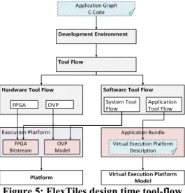
The complete design flow from the expected input to the virtual and hardware platform is depicted in Figure 5. Every block in Figure 5 will be explained in more detail in the following subsections. The expected input for the design flow is an application graph as C code. This C code will be processed within the development environment box to generate an architecture description. The complete tool-flow is further divided into the hardware and software tool-flow. The hardware tool-flow is responsible for the generation of the FPGA bitstream for execution on the FPGA emulator as well as the OVP model for the simulation platform. The software tool-flow is split into the system flow for generating the virtualization layer and the bootloader, and the application flow that compiles the C code for the available processing elements which is summarized as application bundle. Finally, platform can be executed on the FDB and in the simulator and the application bundels can be loaded into their virtual execution platforms.
A. Development Environment
Three input methods are available to the designer depending on the application complexity, namely SimplifyDE, Static DataFlow-C (SDF-C) and SpearDE, described in the following subsections.
1) SimplifyDE
SimplifyDE is a project modular framework supporting the user in the process of creating a hardware platform and evaluating an SDF-application by providing an easy-to-use graphical interface for designing the hardware, mapping the tasks of the application and prototyping it. SimplifyDE uses the high-level simulation framework OVP as backbone for early development but is able to export fully compatible platform and application descriptions used in the hardware tool-flow.
The OVP simulation framework serves the separation of the software application development from the hardware development, offering fast platform recompilation and execution in conjunction with strong debugging capabilities. OVP uses binary translation to execute applications cross-compiled for the targeted architecture in a simulation environment. Since OVP is an instruction set simulator not simulating the timings of the underlying hardware platform, the simulation runs fast and allows the rapid prototyping of complex applications like the Number Plate Detection described in section III.B. To provide high compatibility and avoid changes in the software architecture several peripherals specific for the FlexTiles hardware architecture are added to
FPGA Bitstream OVP Model Application Graph C-Code Application Bundle Virtual Execution Platform
Description
Figure 5: FlexTiles design time tool-flow
the simulation model. One is a DMA peripheral which abstracts the behavior of the NoC used in the hardware and models it in the virtual platform so that it can be used with the same driver codes as on the hardware emulator.
Providing the option to simulate behavior of hardware accelerators as used in the eFPGA, another peripheral modelling the AI uses semihosting technology. This allows the native execution of application code on the host machine. The AI model in OVP exposes the same interface to the platform as on the hardware, however the execution is performed in the semihosted environment via a callback. This allows a HLS-style usage of the model by inserting any C-code into a predefined routine which can request input data and push output data back to the platform. Since the remaining virtual platform is halted during the execution of semihosted code, the result of a semihosted function is available in the system immediately after its execution. Besides the native execution, the semihosting technology allows the access to all ressources available on the host machine running the simulation environment. Therefore, peripherals modelling the input and output devices available on the hardware emulator can read in images files and store the resulting images on the host.
2) Static DataFlow-C
The second input method is SDF-C, the C-based input language to specify additional semantics for nested loop programs in the Streaming Compiler. It is a subset of the syntax of the C programming language which aim is to model a static data flow graph of communicating processes in C. The Streaming compiler is further assisted by explicit pragmas in the source code that identify the loop to be partitioned and the boundaries between processes. These pragmas also explicitely identify the kind of node on which each task will be executed (GPP, DSP of eFPGA).
With the code in this form, the Streaming compiler can transform the loop code into a graph, identify the communication between the nodes, and identify the input and output data of the data flow graph. It also generates actor code for each task corresponding to its mapping (e.g. DSP code). The output of this step is used in the software tool-flow. The SDF-C code can also be imported into SimplifyDE for further evaluation.
3) SpearDE
SpearDE [13] is a tool for transforming and generating code for different targets (e.g. General Purpose GPUs). After modelling the application and the architecture, SpearDE gives the user the ability to manage data and taks parallelism and also perform space and time optimisations (automatic communication generation, task fusion and scheduling).
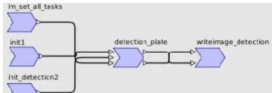
In the framework of the FlexTiles project, it is used to map an application to the FlexTiles architecture, resulting in the generation of an SDF-C code in which pragmas reflect the mapping of each task. The FlexTiles architecture model reflects the number of GPPs and DSPs available in the design and also include the eFPGA for targeting hardware accelerators, all connected through a NoC component. Additional information about communication performance through the NoC is not required since we only use SpearDE for a behavioural model. The application is modeled as a non
cyclic graph of task which formalism is derived from Array-OL [14]. An example for the number plate detection is depicted in Figure 6. It is further discussed in section III.B.
The application graph can either be created by hand or imported from C99 code by respecting some coding rules using PIPS [15]. The mapping is done manually by the user for each task. When communicating tasks are mapped onto different execution units, SpearDE generates memcopy calls annotated with pragmas that are used by the streaming compiler. If the C99 code is already annotated with specialized SDF-C pragma annotations, the SpearDE can be skipped and the C99 code will serve as input for the SDF-C streaming compiler.
B. Hardware Tool-Flow
The hardware tool-flow targets the FPGA emulator and the OVP simulation. In the first step of the tool-flow it takes the abstract hardware description and expands this into a complete description, generates all the necessary files for the Software Tool-Flow, this includes the operating system, libraries and a device tree describing the hardware instance. The second step of the tool-flow can either target the FPGA emulator, generating a synthesizable Xilinx XPS project, or generate a platform description that can be compiled into an executable OVP model.
C. Software Tool-Flow
The software tool-flow is divided into the system and application tool-flow. The application tool-flow requires the application graph generated by the SDF-C streaming compiler and the architecture description. Then, all available resources are analyzed in order to to perform the mapping of the application graph to the available resources. The task of the mapping step is to generate different mapping instances for the current application graph. Mapping entails the assignment of actors to processing tiles (GPP, eFPGA, DSP) and the building of constraints for design space exploration such as instruction/data memory sizes and available processing elements. For each generated mapping, a high-level model of the respective mapping executed on the hardware platform is constructed. With these models, the throughput of the respective mappings are calculated. Additionally, several configurations have to be determined for each mapping such as:
Placement of FIFOs to communication memories
Size of each FIFO
Size of the virtual GPP (TDM slots, memory)
Schedule for Real-Time Operating System (RTOS)
Communication memory requirements
Set of required network connections
The output from the mapping step is then used for code generation of the RTOS boot-up and configuration and of the application graph instantiation. The generated code contains information about the platform description, boot-up code for each virtual processor, setup code for the application graph, and program code and wrappers for each actor.
The system tool-flow generates the code of the resource manager, the virtualization layer, the RTOS, and of the multitile loader based on architecture description. The functionality of each component is well defined thus each component just needs to be adapted to the respective architecture description. The generated code provides the functionality for the RTOS bootloader and of the virtualization layer. After compilation, the output will be sent to the respective execution platforms.
D. Application Bundle
The application bundle receives its input from the application tool-flow. The main task of the application bundle is to bundle the input information in a way that it can be easily accessed and loaded at run-time. The bundle is stored as the Executable and Linkable Format (ELF) because it is already used in the normal compilation flow, is well known, is easily parseable in the running system, and many tools are available to modify it. The bundle uses a hierarchical structure in order to access the parts belonging to different processing tiles. For instance, the parts belonging to one GPP tile are contained in one sub-bundle. A sub-bundle is another ELF file that is embedded in a section of the main ELF file. The hierarchical structure enables the reuse of the existing compilation flow without the problems of duplicate section names when using more than one GPP tile. All data contained in the bundle is stored in binary form. This includes the compiled application code and also the virtual platform configuration. The bundled application is then sent to the virtual execution platform model for execution.
E. eFPGA Tool-Flow
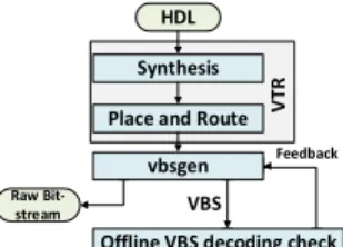
The associated development flow for hardware
accelerators, presented in Figure 7, is based on the Verilog-To-Routing (VTR) framework [16] and on a custom backend. Starting from a C representation of the hardware task, a Verilog or VHDL RTL model of the task is created with dedicated tools. This RTL model is then passed through the VTR flow to generate placement and routing data suitable to the eFPGA logic fabric architecture. Our custom backend uses the synthesized task and its placement and routing data in order to create an in-memory model of the task and to generate raw bit-streams and VBS.
III. EVALUATION OF THE APPLICATION DESIGN FLOW
In this section the application implementation for the FDP will be discussed. Within the FlexTiles project an application for number plate detection as well as the SUSAN application (“Smallest Univalue Segment Assimilating Nucleus”) were implemented. The SUSAN application can be used for edge and corner detection and is introduced in [17]. The implementations are discussed in the respective subsections.
A. SUSAN
The Susan application was initially developed by the Oxford Centre for Functional Magnetic Resonance Imaging (MRI) of the brain, Department of Clinical Neurology, Oxford University, Oxford, UK [17]. The main goal of the program was to highlight interesting regions on the MRI image to aid the doctors when reviewing the MRI results. The original code was sequential ANSI C. In an earlier case-study at the Eindhoven University of Technology, the Susan application was converted into a Dataflow application and was ran in a SystemC simulator. The dataflow graph of this application is depicted in Figure 8. The blue boxes show the processing kernels, the green boxes indicated the information being relayed. To use this application as an interresting use-case for validating the FlexTiles tool-flow the application was modified:
Use the DVI in/out framebuffer as input and output:
The FDB has DVI in/out and this is also modelled in OVP, by using this we can validate that both can be used identical.
Add pre-processing filters: We want to demonstrate
that application can adapt themselves to changes in the environment, for visual application adjusting to changing light condition is a realistic scenarios.
Analyze the execution and optimize the
data-flow.The original dataflow graph of Susan is small and all the production and consumption rates are 1. To complicate the effort needed to bring the application into a quiescence state, we introduced edges with non-identical production and consumption rates. To stop an application a specific number of actor executions has to be made first.
To port the application it was imported into the SimplifyDE framework, see Figure 9, and the above described changes where done on OVP model, allowing changes to be tested early while having access to GDB and other debug tools.
In order to make use of the DVI input and output of the FDB, it was necessary to modify the GetImage and PutImage actors to fetch the appropriate data from the input framebuffer and write the result back to the output framebuffer. These were the only changes to the application that were specific to the FlexTiles platform architecture.
HDL Synthesis
Place and Route V
TR
Raw Bit-stream
vbsgen
Offline VBS decoding check Feedback VBS
Figure 7: eFPGA development tool-flow
GetImage PreProcess SusanUsan SusanDirection SusanThin PutImage
Filter MCU_Block MCU_Edge Strength MCU_Edge Direction GETIMG_state MCU_Block MCU_Block MCU_Block MCU_Edge Strength MCU_Edge Direction MCU_Block
Figure 8: SUSAN Application
The added pre-processing filter enables the enhancement of dark input images and thus the SUSAN algorithm can detect more features. Figure 11 shows a comparison of the detected features in an unmodified and an enhanced input image. The enhanced image has more features detected in the darker areas of the image. Therefore this actor has two different implementations: the filter and a No Operation (NOP) implementation, at run-time we can switch between these two scenarios. Within the third step the execution times have been analyzed and the data flow graph has been optimized. The execution time of the SUSAN application itself is varying depending on the features of the actual input image, an image with more possible edges takes more cycles processing. However, a general bottleneck was found with the SusanDirection kernel. Therefore, the SusanUsan and SusanDirection kernel have been parallelized to share the workload between multiple GPPs, as depicted in Figure 10. Because of the data-parallelization we introduced edges that have different consumption and production rates. This is an interresting use-case for when the application needs to be stopped for reconfiguration.
Now that the application was successfully running on the FDP we introduced rules evaluated by the Virtualization Layer for reconfiguring the application. To force regular reconfigurations we switch to the NOP scenario after 400 graph iterations and back to the filter scenario after 500. The rules are depicted in Table 1.
Table 1: Scenario rules
ID Operator Value Thr. From scen. To scen.
1 >= Iterations 400 Filter NOP
2 >= Iterations 500 NOP Filter
With the FlexTiles tool-flow the integration of the SUSAN application into the FlexTiles platform was eased. Changes to the application graph could be verified with a single command and changes to the code could be quickly tested. The application bundle created for OVP could be directly ran on the FDB allowing us to verify the execution times. The original implementation took around 33 seconds for a 800 times 600 pixel image, after the changes to the FlexTiles platform, the image decoding takes around 6 seconds. The reconfiguration of the pre-processing filter (Reloading the GPP from a NOP to the filter implementation) took around 1 ms. An output capture of the board with the output of the SUSAN application and
information from the Virtualization Layer is shown in Figure 11.
B. Number plate detection
The number plate detection application is based on mathematical morphology operators such as dilation and erosion to detect any number plate appearing in a sequence of images. The original application consists in three parts:
Detection: number plates are detected when they
appear for the first time in a frame.
Tracking: once a number plate has been detected, it
can be tracked in the following frames. Tracking is basically the same algorithm as the detection part but executed on a small subset of the.
Optical Character Recognition (OCR): for converting
the detected number plate into plain text for further processing.
OCR has not been implemented. Hence, the application consists in two main blocks for detection and tracking. It processes 640 by 480 pixels portable graymap images. The result is displayed via the DVI output of the FDB.
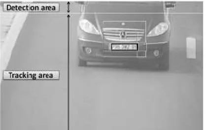
This application was first designed to run on a desktop computer with no embedded constraints. The code has also been ported to GPGPUs and is based on a shared-memory architecture that does not comply with our embedded platform with limited local memories. In order to reduce memory requirements and speed up the algorithm, detection is only performed on the upper 50 pixel lines of each frame. Indeed, we assume a given direction for the vehicles. Tracking is then performed on the remainder of the frame. Figure 13 depicts this strategy.
GPP1 GPP 4 GPP 5
GPP 3
GPP 2
GetImage PreProcessFilter SusanThin PutImage
MCU_Block GETIMG_state MCU_Block MCU_Edge Direction MCU_Block SusanUsan SusanDirection MCU_Edge Strength MCU_Block SusanUsan SusanDirection MCU_Edge Strength MCU_Block MCU_Edge Direction MCU_Block MCU_Edge Strength
Figure 10: SUSAN application - mapped and parallelized
Figure 9: SUSAN import into SimplifyDE
SpearDE was the entry point for using the tool-flow as the application structure is quite complex and refactoring was limited to the minimum. The code was directly imported using PIPS and the resulting graph is depicted in Figure 6. The entire code was mapped on one GPP. The mapping is shown in Figure 12. The different colours reflect the task being mapped to different segments. Communication tasks between intialization tasks and the detection itself have been
automatically generated. Communication between the
detection and the image display task are hidden within the loop fusion (noted F on the graph) which is responsible to merge loops in order to stream results as soon as they are available (rather than waiting for a full frame to be processed).
The algorithm execution takes about 25 seconds per frame on a single GPP, compared to about 100 ms with the initial algorithm on a laptop. This is due to the fact that the algorithm was not developped with embedded requirements in mind. Modifications in the algorithm were limited to the minimum as this it is a demonstration of the tool-flow and its capability to import legacy C code.
IV. CONCLUSION
In this paper we described the tool-flow and architecture of the FlexTiles heterogeneous many-core platform, as well as the process of developing and porting applications to it. During this process the strength and weaknesses of the FDP flow became apparent. It does not solve all the difficulties of porting an application to an embedded heterogeneous many-core platform, it does however significantly reduces the development effort. The tool-flow allows the developer to write out the basic structure of the application at a very high level (actors and edges) or have this generated from existing code. Therefore the developer only needs to care about the implementation of the actual application. The OVP model of the platform allows for quick prototyping and provides debugging tools, like gdb, that are often not available in embedded systems. A good example of this is that often with porting large applications a big 'one-shot' effort has to be done to shrink it down, only allowing verification afterwards. With OVP we can start off with a single processor large platform and during the rewrite, slowly shrinking it down and extending it to a heterogeneous many-core without spending hours synthesizing hardware. The number plate detection application
was used to show a use-case like this, the porting here was not perfect as it became clear the application needed more than initially estimated refactoring to be suited for an embedded system, however this was caught early on. For other applications, like Susan, the porting was easier and we used the FlexTiles flow to optimize the application for the many-core platform and to exploit the run-time optimizations by allowing the Virtualization Layer to reconfigure part of the application to adapt to the changing environment. Once working in OVP we could run the generated application bundle on the FDB.
REFERENCES
[1] P. Burgio und et. al., „A HLS-Based Toolflow to Design
Next-Generation Heterogeneous Many-Core Platforms with Shared Memory,“ in 12th IEEE International Conference on Embedded and Ubiquitous
Computing (EUC), 2014.
[2] B. Fort und et. al., „Automating the Design of Processor/Accelerator
Embedded Systems with LegUp High-Level Synthesis,“ in 12th IEEE
International Conference on Embedded and Ubiquitous Computing (EUC), 2014.
[3] F. Thoma und et. al., „MORPHEUS: Heterogeneous Reconfigurable
Computing,“ in Field Programmable Logic and Applications (FPL), 2007.
[4] A. Deledda und et. al., „Design of a HW/SW Communication
Infrastructure for a Heterogeneous Reconfigurable Processor,“ in Design,
Automation and Test in Europe (DATE), 2008.
[5] N. Neves und et. al., „Morphable hundred-core heterogeneous
architecture for energy-aware computation,“ Computers Digital
Techniques, IET, Bd. 9, Nr. 1, pp. 49-62, 2015.
[6] L. Schor und et. al., „EURETILE Design Flow: Dynamic and Fault
Tolerant Mapping of Multiple Applications Onto Many-Tile Systems,“ in Parallel and Distributed Processing with Applications (ISPA), 2014.
[7] A. Nelson and et. al., "CoMik: A predictable and cycle-accurately
composable real-time microkernel," in Design, Automation and Test in
Europe Conference and Exhibition (DATE), Dresden, March 2014.
[8] A. Nieuwland and et. al., "C-HEAP: A Heterogeneous Multi-Processor Architecture Template and Scalable and Flexible Protocol for the Design
of Embedded Signal Processing Systems," Design Automation for
Embedded Systems, vol. 7, no. 3, pp. 233-270, 2002.
[9] G. Marchesan Almeida, Adaptive multiprocessor systems-on-chip
architectures: Principles, methods and tools, LAP Lambert Academic Publishing, 2012.
[10] K. Goossens, J. Dielissen and A. Radulescu, "AEthereal network on
chip: concepts, architectures, and implementations," Design Test of
Computers, IEEE, vol. 22, no. 5, pp. 414-421, 2005.
[11] R. Brillu and et. al., "Accelerator Interface, a keystone for heterogenous "MPSoC" architectures," in Design, Automation & Test in Europe,
Grenoble, France, 2013.
[12] C. Huriaux und et. al., „Design Flow and Run-Time Management for
Compressed FPGA Configurations,“ in Design, Automation and Test in
Europe, 2015.
[13] M. Barreteau, R. Barrère und E. Lenormand, „Programming GPUs from High Level Data Flow Models,“ in Patterns for Parallel Programming
on GPUs, F. Magoulès, 2014, pp. 73-108.
[14] A. Demeure und Y. Del Gallo, „Array-OL: An Approach for Signal
Processing Design,“ in SAME, System On Chip session, 1998. [15] „ PIPS: Automatic Parallelizer and Code Transformation Framework,“
2015. [Online].
[16] J. Rose und et. al, „VTR project: Architecture and CAD for FPGAs from Verilog to Routing,“ in International Symposium on
Field-Programmable Gate Arrays, 2012.
[17] S. M. Smith and J. M. Bradley, "SUSAN—A New Approach to Low
Level Image Processing," International Journal of Computer Vision, vol. 23, pp. 45-78, 1997.
Figure 12: SpearDE application graph after mapping
Figure 13: Number plate detection example