HAL Id: hal-01767609
https://hal.archives-ouvertes.fr/hal-01767609
Submitted on 16 Apr 2018
HAL is a multi-disciplinary open access
archive for the deposit and dissemination of
sci-entific research documents, whether they are
pub-lished or not. The documents may come from
teaching and research institutions in France or
abroad, or from public or private research centers.
L’archive ouverte pluridisciplinaire HAL, est
destinée au dépôt et à la diffusion de documents
scientifiques de niveau recherche, publiés ou non,
émanant des établissements d’enseignement et de
recherche français ou étrangers, des laboratoires
publics ou privés.
A magnetic climbing robot to perform autonomous
welding in the shipbuilding industry
Olivier Kermorgant
To cite this version:
Olivier Kermorgant. A magnetic climbing robot to perform autonomous welding in the shipbuilding
industry. Robotics and Computer-Integrated Manufacturing, Elsevier, 2018, 53. �hal-01767609�
A magnetic climbing robot to perform autonomous welding in the
shipbuilding industry
IOlivier Kermorgant
Laboratoire des Sciences du Num´erique de Nantes LS2N, ´Ecole Centrale de Nantes
Abstract
In this paper we present the mechanical and control design of a magnetic tracked mobile robot. The robot is designed to move on vertical steel ship hulls and to be able to carry 100 kg payload, including its own weight. The mechanical components are presented and the sizing of the magnetic tracks is detailed. All computation is embedded in order to reduce time delays between processes and to keep the robot functional even in case of signal loss with the ground station. The main sensor of the robot is a 2D laser scanner, that gives information on the hull surface and is used for several tasks. We focus on the welding task and expose the control algorithm that allows the robot to follow a straight line for the welding process.
Keywords: Continuous track, welding robot, climbing robot
1. Introduction
In the advanced manufacturing area, one chal-lenge is to extend the use of autonomous or col-laborative robots in several industries such as car companies, plane and ship building or renewable en-ergies. Whereas most of the innovations deal with traditional or mobile robot arms in classical manu-facturing plants, another source of productivity can be found in more exotic locations: large structures such as an aircraft or a ship indeed have their own constraints when it comes to mobile robotics. In this work we design a mobile robot able to navi-gate on vertical steel surfaces such as ship hulls. The robot can perform various tasks, either au-tonomously or in tele-operation depending on the complexity. Currently, hull welding is performed manually by a welder mounted on a boom lift or scaffoldings. This is both dangerous and costly, as the typical size of a ship is some hundred meters length and a few tens of meters high. Besides, due to the thickness of the hull, several passes have to
I 2018. This manuscript version is the accepted preprintc
and is made available under the CC-BY-NC-ND 4.0 license http://creativecommons.org/licenses/by-nc-nd/4.0/
Email address: olivier.kermorgant@ec-nantes.fr (Olivier Kermorgant)
be performed (up to 10). A typical ship thus re-quires several kilometers of straight line welding. Human welder expertise is far from being fully ex-ploited in this task, and it can benefit from an au-tonomous process. The stakes for the ship builder are to reduce lifts or scaffoldings use, and to have their welders available for more complex tasks such as corners or welding in small places where adapt-ability is crucial.
This task requires the accurate positioning of an embedded welding torch. The torch is carried by a 2-degrees of freedom arm located at the rear of the robot and benefits from laser scanner feedback for the analysis of the welding joint. The motion law of the torch is not detailed and we focus on the capabilities of the vehicle in terms of alignment and positioning with regards to the welding joint, which drives the position of the welding torch. Absolute localization on the hull, or longitudinal positioning along the welding joint, are not considered in this work. Welding results are presented to show the reliability of the process.
Most of the works on climbing robots focus on mechanical design and adhesion principle. A survey [1] indicates that the two most popular approaches for climbing robots are the use of suction force and, when the surface allows it, magnetic force.
in [2] for the inspection of radioactive cylindrical tanks. The payload is only 3 kg. Alternatively, in [3] a quadruped walking robot is presented with suction pads at each of the 4 contact links. The control of such a robot is of course quite tedious. In [4] a low cost wall climbing robot is proposed. Classical tracks are used with a vacuum pump that increases the grip on the surface. The payload of this robot is only 500 g.
Magnetic force-based robot may use electromag-nets [5, 6], which are interesting as they can be ac-tivated at will and increase the control possibilities of the platform. On the other hand, permanent magnets can be use with magnetic wheels [7, 8]. The main advantage is that no energy is spent on the adhesion, but it makes the control more diffi-cult and requires more power in order to cope with the friction between the wheels and the surface. A magnetic tracked robot is presented in [9] with an emphasis on the sizing of the magnetic pads. The goal is to perform oil tanks inspection with manual control of the robot.
Alternative technologies to suction and magnetic forces have been investigated. In [10],thermoplastic adhesive bonds are used instead of magnets or suc-tion pads. Even if it leads to a very high payload, the number of cycles is limited and this would in-duce too many maintenance operations for the ship industry. Another technology has been proposed for non-magnetic wall climbing [11], but again the payload is only 100 g and the control is not auto-mated.
High-payload wall climbing robot designs are pro-posed in [12, 13]. Here the vehicle is equipped with wheels and an adjustable magnet allows the con-trol of the adhesion force, allowing up to 50 kg pay-load. Although the robot is designed for welding, no performance analysis is done for the arm posi-tioning and the control also seems to be manual. Another manually-driven robot is proposed in [14], using magnetic tracks for hull inspection.
In our case, safety imposes that the robot should not fall even in the case of power failure. In addi-tion, the robot is designed to work on ship hulls. That is why we chose magnetic tracks, even if as we will see it leads to constraints on the navigation part.
Most of the mentioned robots assume manual control. On the opposite, in [15] a magnetic robot is proposed with a laser feedback for autonomous in-spection. The design is similar to [13] with wheels and adjustable permanent magnets. The laser
feed-back is similar to our case, though we need a higher accuracy due to the welding task. Navigation are usually not studied for tracked vehicles, as their au-tonomous modes are often used in large areas where GPS feedback is available and where rough accu-racy is enough [16]. Improving open-loop odometry relies on the study of the track-soil interaction [17] which may not be enough for welding.
In this work, we focus on the laser feedback from [18], that proposes several trajectories for the weld-ing torch that can be computed from the weldweld-ing joint 2D profile. This approach is classically used for non-mobile welding robots [19, 20] or robot that switch between motion and welding [21].
Compared to previous works, we propose a whole mechanical and control design for autonomous hull welding. The prototype has been tested on real ship hulls, which has revealed that the key feature is the autonomous line following in order to ensure accurate positioning of the welding torch.
We exploit the laser feedback needed for the weld-ing, to perform joint tracking. For cost reasons only one laser scanner is considered on the robot. The contribution lies in the design, control law and state estimation of the mobile base. In Section 2 the general design and components of the robot are de-tailed. We also focus on the main mechanical chal-lenge, that is the magnetic caterpillar. The control architecture is then presented in Section 3, with the design of an estimator and control law to per-form welding joint tracking. Experiments on joint tracking and welding results are then presented in Section 4.
2. Overall design
In this section we detail the mechanical design and the components of the robot. The starting point for the sizing of the platform was the weight and payload that directly impact the number of magnets, hence the general size of the robot. The current form factor is 80 cm length and 50 cm width, with 100 kg total weight including the weight of the external cables (power supply and welding torch cable). The robot structure is composed of aluminum. A 600 W external power supply delivers 3x48 V. We first list the robot components before detailing the sizing of the magnetic track.
2.1. Components
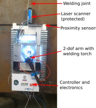
The prototype is shown in Fig. 1. The laser scan-ner is hidden behind a protective layer. On the rear
Controller and electronics
Laser scanner (protected)
2-dof arm with welding torch Proximity sensors
Welding joint
Figure 1: Overview of the mobile robot in vertical position on a steel surface. Front support carry proximity sensors. The laser scanner is protected from external light. Embed-ded electronics are on the rear panel and dispatched around the CompactRio. The two external cables are the power sup-ply (grey) and Ethernet connexion (blue). Welding is being performed at the center of the robot.
panel (bottom), the embedded controller is visible with its modules wired to the other pieces of hard-ware. At the center of the robot is the 2-degrees of freedom arm equipped with a functioning welding torch.
2.1.1. On-board computer
The controller is a National Instruments Com-pactRio. It features a dual-core 1.33 GHz Intel Atom processor running a Linux real-time kernel. The CompactRio also features a Xilinx FPGA. All of the code is developed in Labview. The real-time kernel hosts most of the programs, except for the arm low-level controllers that run on the FPGA and the user interface that runs on a remote computer. 2.1.2. Continuous tracks and motors
The continuous tracks and their magnetic pads have been sized to carry the robot and its payload. The sizing is detailed in Section 2.2. The track has 24 pads in contact with the surface with 25 kg grip per pad. This induces a smooth motion without dis-continuities, hence no disturbances on the welding process. The pads are composed with neodymium iron boron magnets protected by aluminum boxes, and are linked with a stainless-steel chain.
Each track is associated with a Motor Power Company brushless servomotor with an input volt-age of 48 V. A planetary gear with 1:195 ratio then delivers up to 42 Nm torque at velocities up to 6 m/min. The motor speed drives have been tuned with the final payload in working condition (robot on a vertical hull) and allow a fast response to the velocity setpoint of the two tracks.
Although some works address the issue of servo-motor cooling in a harsh welding environment [22], this was not considered in the current prototype. 2.1.3. 2-degrees of freedom arm
At the center of the robot a 2-degrees of freedom arm is mounted in order to control the position of the welding torch. Each axis is driven with a 24 V DC motor. The motors are driven through Com-pactRio modules allowing real-time position control and feedback. A first calibration step was needed to register the axis with regards to the laser mea-surement.
2.1.4. Laser scanner
The embedded laser scanner is a MEL scanner, with a measuring range of 84 to 204 mm and a
max-imum width of 80 mm, which corresponds to an an-gle opening of±15o. The resolution if 0.06 mm in
range and 0.14 mm in X-direction. The laser con-nects to the CompactRio with Ethernet and sends the X-Z position of 290 points at 100 Hz. During the welding process, some outliers appear in the laser scan due to the welding light. They can easily be filtered out.
2.1.5. Proximity sensors
As the robot may be placed on unfinished hulls, it could fall by simply moving out of its own con-tact surface. Four Sharp Infrared proximity sensors have thus been mounted at each corner. The volt-age output is acquired by an analog IO module on the CompactRio. Again, during the welding some irregular measures happen but they can be elimi-nated through a hysteresis filter.
2.1.6. Welding process
In the current state of the robot, the welding torch is directly connected to the welding ground station through a cable that provides shielding gas and wire. On longer distances, it will be necessary to mount a wire subfeeder on the robot.
2.2. Magnetic track sizing
The main challenge of the mechanical design is the sizing of the magnetic tread. Indeed, safety protocols in the considered industry force a mag-netic device to have a grip equal to at least five times its weight. This is due to the possibility of slippery surface in case of humidity or even rain. The robot also has to be able not to fall even in one caterpillar is broken. The considered robot and payload weighting about 100 kg, this means that each caterpillar has to have an attractive force of at least 500 kg.
This is where the magnetic track strongly differs from a classical tracked vehicle. Indeed, the attrac-tive force caused by the magnets is far greater that the sole gravity in the case of a vehicle moving on a horizontal plane. Rotational motions, which are in-duced by having the two tracks running at different velocities, imply that some of the pads are actually slipping on the contact surface. In our case, first ex-periments have shown that rotational motions can be perfectly performed on the ground but as soon as the robot is on a magnetic surface the attractive force is such that the chain is subject to very high efforts. This induces deformations in the chain and
can also make it jump off the gear.
In order to cope with this phenomenon, a mini-mal radius of curvature is imposed during the mo-tion. As we will see in Section 3.2, the use of mag-netic tracks also induces uncertainties during au-tonomous control. This aspect will be detailed in Section 3.3.
Finally, the presented sizing induces no slippery motion on wet hulls. In practice, the welding torch is protected from the rain, and the welding process heats the hull and dries out its surface around the robot position. We now present the software and control architecture of the robot.
3. Control design
In this section the general control architecture is presented. We then focus on laser-guided line tracking and present an Extended Kalman Filter used to estimate the angle between the robot and the welding joint.
3.1. General control architecture
As in multi-process software, the Labview de-sign paradigm allows the definition of several par-allel loops that interact through shared variables. The designed software is composed of the following loops:
1. The state machine is the core of the control architecture. Depending on the state of the system (manual control, welding process...) it sends different setpoints to the track motors and the arm. The state machine also includes the security checks based on the proximity sen-sors in order to cancel any motion making the robot fall off the hull.
2. Two user-interface loops at 50 Hz: one for the inputs and one for the display.
3. A loop for each sensor and actuator running at different frequencies depending on the hard-ware. The laser scanner loop typically runs at 100 Hz while the proximity sensors loop is only at 10 Hz. The low-level loops of the arm mo-tors include cascaded PID for position or ve-locity control.
4. A low-level control loop for laser-based line tracking at 50 Hz. This is used during the welding process and does nothing if the robot is in another state.
Ready to begin welding
End of the welding joint Welding pass Aligned with the joint
Backward alignment Above the welding joint
Forward alignment Robot placed on the hull
Manual control
Waiting for manual control
Back for the next pass
Last welding pass performed
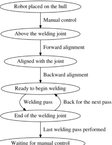
Figure 2: Graph of a typical process. Manual control is required before and after the welding.
• Manual: both the mobile base and the arm are manually controlled. This is used to perform the approach of the welding joint and to cali-brate the arm.
• Alignment: here the vehicle automatically aligns with the joint at a given forward veloc-ity. No welding is performed, the goal is to be sure the vehicle is aligned.
• Welding: in this state the vehicle has a for-ward velocity coming from the welding control and the angular velocity is controlled to stay parallel to the joint. The arm follows a YZ tra-jectory that is defined for the welding process. • Return: when a welding pass is over the robot goes backward to perform another pass. The arm is motionless while the vehicle follows the welding joint in reverse.
The sequence between the main steps is described in Fig. 2. A manual control is typically required to approach the joint and to move to the next one. Before actual welding, an automated alignment is performed.
We now detail the laser-guided joint tracking that is used during the Alignment, Welding and Return states.
Raw profile Edges Barycenter
Figure 3: Typical laser profile with the welding joint (Y and Z scales have been changed). Edges (red) are extracted, then the barycenter (green) is computed. Units and angles are intentionally not displayed.
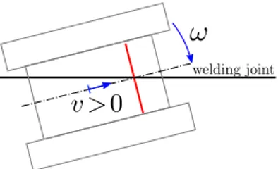
Figure 4: Schematic of the robot above the welding joint. The laser (red beam) measures the distance d. The angle θ and distance y between the origin O and the joint are unknown. The distance l between the laser and the origin is also unknown.
3.2. Laser-guided navigation
Laser-guided navigation is used during the weld-ing process in order to ensure the robot stays par-allel to the welding joint. Only the angular velocity ω is controlled, as the linear velocity v is imposed by the welding process.
Other strategies for line tracking include vision [23] and trajectory tracking [24]. In the consid-ered environment, vision is however unreliable due to light conditions and poor contrast between the hull and the joint. Trajectory tracking requires a global frame where the robot and the trajectory are defined. Here the only exteroceptive sensor is a laser and cannot reconstruct the absolute pose.
Assuming the robot lies on the welding joint, the embedded laser provides the joint profile that can be processed to extract feature points. A typical profile is represented on Fig. 3 with a seam of ap-proximately 3 cm width × 2 cm depth. The raw profile is first smoothed with a Savitzky-Golay fil-ter [25]. For joint tracking, we are infil-terested in ex-tracting the two edges of the hull parts that are to be welded (red diamonds on the figure). These edge points are found by an iterative robust line fitting
algorithm [26] on the hull. Line fitting is performed on an increasing number of (leftmost or rightmost) points. When the last considered points are sys-tematically outliers for several iterations then the edge point is assumed to be the last inlier. Other methods have been proposed to perform weld joint detection and tracking [27, 28] Once the edges have been found, the barycenter of the joint is computed according to previous works [18]. Green’s theorem is used to compute the position of the barycenter (green in Fig. 3). The barycenter is robust to small variations of the edges detection and is assumed to draw a straight line through the joint. Other features points, used to control the position of the welding torch, are also extracted but not displayed. The general configuration of the robot with re-gards to the welding joint is shown in Fig. 4. The origin O denotes the instantaneous center of rota-tion. Unlike classical unicycle robots [29], the posi-tion ofO is not known for tracked vehicles as an-gular motions imply that some pads are slipping while others are not. y is the distance betweenO and the joint, l is the distance between O and the laser beam and θ is the orientation. These values are linked through the equation:
d = y/ cos θ + l tan θ (1) As ˙y = v sin θ, the derivative of (1) is:
˙
d = −yω sin θ/ cos2θ + v tan θ
+ ˙l tan θ + lω(1+tan2θ) (2) We now detail the continuous transfer function be-tween the angular velocity ω and the distance d. In the desired work configuration, the robot state is centered and aligned with the joint, and we can assume that for a particular configuration the force repartition on the tracks is stable and l does not vary. (2) is thus linearized around the position (y = 0, ˙l= 0, θ 1):
˙
d = vθ + lw (3) The Laplace transform of (3) yields:
sD(s) = v
sΩ(s) + lΩ(s) (4) where s is the Laplace variable. The corresponding transfer function H(s) = D(s)/Ω(s) yields:
H(s) = D(s) Ω(s) =
v + sl
s2 (5)
The system thus has two very different behaviors, depending on the moving direction v.
Figure 5: Going forward. If d is regulated at 0 (joint in the middle of the laser beam) then the robot naturally aligns with the welding joint.
Figure 6: Going backward. If d is regulated at 0 (joint in the middle of the laser beam) then the robot naturally moves away from the joint.
3.2.1. Going forward
If vl ≥ 0 then the system is minimum-phase. This is the case during Welding state, as the laser scanner is located at the front of the robot (l > 0). A simple PID from d to ω is used to control the angular velocity, inducing high stability and preci-sion as represented on Fig. 5. Even if the system has a double integrator, another Integrator term is needed in the controller. Indeed, the radii of the tracks may be subject to small changes because of surface defects or accumulated iron filings on the magnets.
3.2.2. Going backward
If vl < 0 then it is non minimum-phase. This is the case when the robot has finished a welding pass and is going back to the starting point. The previous controller cannot be used since regulating d to 0 does not induce staying parallel to the joint, as represented on Fig. 6. However, in this state we only aim at going back to the starting position while tracking coarsely the joint. Small variations on d are thus acceptable and we regulate an error composed of the distance d and an estimation of the angle θ:
where α is a tuning parameter. The corresponding transfer function yields:
He(s) =
E(s) Ω(s) =
v + (l + α)s
s2 (7)
We see that even if v < 0, the zero of He is at
−v/(l+α) and can thus be made negative by choos-ing α <−l. Actually, if we simulate a virtual laser located at l0 in the rear direction then the output d0 of this laser would be:
d0= d− (l + l0) tan θ (8) This is equivalent to (6) for small values of θ. En-suring α <−l in (6) amounts to having l0 > 0 in (8), which means the virtual laser is indeed at the rear of the robot. The forward control law can thus be used from this virtual laser, using a PID from e to ω.
In order to use this controller an estimation of θ is required. We now present the Extended Kalman Filter that is used to do so.
3.3. Kalman filter for angle estimation
While the laser scanner provides very accurate measurement of the joint profile, it lacks the ori-entation of the robot which is needed during back-ward motion. An Extended Kalman Filter (EKF) [30] is thus used to estimate the missing value. The state of the robot is chosen as (v, ω, y, θ, l), and we assume no time variation for (v, ω, l) in the filter definition. The continuous formulation of the state transition model yields:
˙v = 0 ˙ ω = 0 ˙ y = v sin θ ˙ θ = ω ˙l = 0 (9)
The available measurements are the position d of the joint barycenter in the laser beam and the en-coders of the tracks which are considered in a dif-ferential drive model [29]. The observation model thus yields: ωl =1rv + b 2rω ωr =−1rv +2rbω d = y/ cos θ + l tan θ (10)
where (ωl, ωr) are the angular velocities of the left
and right motors, r is the track radius and b is the
Laser scanner at the center
welding torch at the back
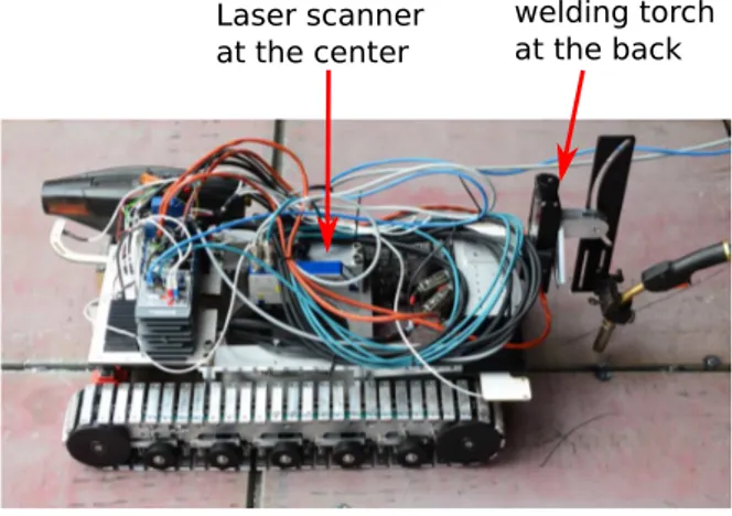
Figure 7: Initial robot design. The laser is at the center, the welding torch is at the rear. Electronics integration was not done yet on this design.
distance between the tracks. The last equation is the same as (1). A classical Extended Kalman Fil-ter is then used with the models (9) and (10) in order to estimate the orientation that is needed dur-ing the backward motion.
4. Experiments
In this section we present some results on au-tonomous line tracking. We first describe the exper-imental setup before analyzing the results. Finally, the actual welding is briefly exposed.
4.1. Experimental setup
In order to have the ground truth for the angle α and the robot state, a second laser scanner is located at the end of the robot. It is not used in the control law or in the state estimation. As described in Fig. 2, the robot is first manually driven above the welding joint. The robot then goes through the following steps:
1. Alignment for 30 s 2. Return for 30 s 3. Welding for 60 s 4. Return for 60 s
In the graphs, the state is indicated as FWD (Align-ment / Welding) or BWD (Return). During the Alignment and Welding steps, the linear velocity is set to +0.02m/s and the steering is regulated through the PID described in Section 3.2.1. Dur-ing the Return steps, the linear velocity is set to −0.04m/s and the steering is regulated through the
PID described in Section 3.2.2.
We are interested in the regulation of d and in the torch position error with regards to the joint. In practice, additional motion of the Y-Z axis is used to perform the welding but its performances mainly depend on the torch position error caused by an un-desired angle between the robot and the joint.
Two robot designs are compared in order to de-tail the compromise that arise between the robot control and the torch positioning. The first one is shown in Fig. 7 and corresponds to the initial design of the prototype. The laser is at the center while the welding torch is at the rear of the mobile base. The idea was to reduce interactions between the weld-ing process and the components of the robot (espe-cially the laser and the computer). We will see that in this case the joint tracking is less satisfactory as a small angle induces a large lateral error on the welding torch. Besides, the welding process itself is not protected from external disturbances such as wind or a small rain. The final design hence cor-responds to Fig. 1, with a laser at the front and a centered welding torch. It is the current design of the prototype and we will show it leads to a smaller position error for the torch.
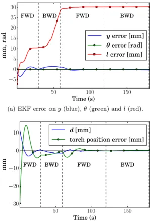
4.2. Initial design: centered laser, torch at the rear In the initial design, the laser scanner is located near the center (l = 0.15m) while the welding torch is at the rear of the robot.
Fig. 8a shows the estimation error of the distance to the welding joint y (blue), the robot orientation θ (green) and the distance l (red). The EKF pre-sented in Section 3.3 allows a fine estimation of y and θ, but due to the large initialization error on l (0.05 m instead of 0.15) this value is not correctly estimated. As the value of l is quite small, it has few impact on the measurement model (10) which makes it difficult to estimate.
This does not prevent the robot from following the joint: Fig. 8b shows that d (joint center in laser scan) quickly reaches 0 in Forward motion. Indeed we have shown in Section 3.2.1 that the steering is stable when going forward. The welding torch being at the rear of the robot, its distance to the joint is highly dependent on the robot angle. Hence, high oscillations can be observed during the first Forward motion.
After 30 s, the robot is in Return state. It is visi-ble on Fig. 8b that the distance d is not regulated to 0 according to (7). The vehicle still roughly follows the line, despite the error on the estimation of l. We
50 100 150 Time (s) −5 0 5 10 15 20 25 30 mm, rad FWD BWD FWD BWD yerror [mm] θerror [rad] lerror [mm]
(a) EKF error on y (blue), θ (green) and l (red).
50 100 150 Time (s) −30 −20 −10 0 10 mm FWD BWD FWD BWD d[mm]
torch position error [mm]
(b) Position (in mm) of the welding joint in the laser beam (blue) and distance of the welding torch (green). Figure 8: Initial design. (a) Estimation error on (y, θ, l). (b) Joint center in the laser scan and torch position error.
can see that the error on d increases while the torch position decreases. The vehicle thus roughly follows the joint and is able to get back to the starting po-sition. After 60 s, the robot is in Welding state. As for the initial Alignment, because of the required steering to center the joint in the laser scan, the torch position error oscillates between -4 and +2 mm at the beginning of the welding. This would typically lead to a bad welding quality for the first centimeters. The position error then converges to 0 and the robot stays aligned during the end of the Welding and the tracking Return state.
We now expose the results from the final design, that leads to a better torch position.
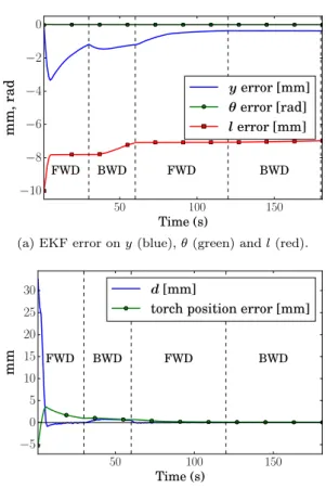
4.3. Final design: centered welding torch, laser at the front
In the final design, the laser scanner is located at the front of the robot (l = 0.50m) while the welding torch is near to the robot center.
Fig. 9a shows the estimation of the distance to the welding joint y (blue), the robot orientation θ
50 100 150 Time (s) −10 −8 −6 −4 −2 0 mm, rad FWD BWD FWD BWD yerror [mm] θerror [rad] lerror [mm]
(a) EKF error on y (blue), θ (green) and l (red).
50 100 150 Time (s) −5 0 5 10 15 20 25 30 mm FWD BWD FWD BWD d[mm]
torch position error [mm]
(b) Position (in mm) of the welding joint in the laser beam (blue) and distance of the welding torch (green). Figure 9: Final design. (a) Estimation error on (y, θ, l). (b) Joint center in the laser scan and torch position error.
(green) and the distance l (red). The larger value of l makes it easier to estimate, and the estimation er-ror reduces over time. As with the previous design, the estimation of y is not perfect but this does not prevent the robot from tracking the joint. As shown in Section 3.2, having the laser at the front improves the gain of the system when going forward. Hence both d and the torch quickly align during the first Alignment step as seen in Fig. 9b. Again, during the Return step between 30 and 60 s, the regulated parameter is a compromise between d and the an-gle, hence a small offset appears while the torch stays at the same distance to the joint. After 60 s, the Welding step begins and d is very quickly reg-ulated to 0. The torch starts with a position error of 0.6 mm that converges to 0 without oscillations. This is within the acceptable error of 1 mm for the first pass on ship hulls. Once the robot is aligned, the torch position error is almost null which results in a very accurate welding process. This continues when going backward after 120 s: both the laser
(a) 3D profile of 1 m welding. Laser scan outliers are visi-ble as peaks. The consecutive passes are shown in different colors.
(b) History of 10 performed welding passes for a 2 m welding. The mean value of the profile is used, hence some registration aberrations. The last pass is about 3 cm wide.
Figure 10: History of the joint profiles. Units and angles are intentionally not displayed due to confidentiality reasons. (a) 3D profiles. (b) Cross-section of average joint profiles for 10 consecutive passes.
and the torch stay centered above the joint. In this analysis only 60 s forward and backward are demon-strated as the robot always stays aligned with the joint after this typical time period.
Comparing the performances of two designs re-veals that from an automation point of view, and as shown in Section 3.2, the initial design induces lower performances both in terms of state estima-tion (larger estimaestima-tion error on l) and in process quality (non desired oscillations of the torch be-fore stabilization). The necessity to be able to stay aligned during the Return phases is caused by the small torch offset that may happen at the beginning of a new welding pass. From a process point of view, having the torch at the center of the robot actually protects the weld from external disturbances. The main drawback of the final design is that the weld-ing is performed near to several robot parts (mag-netic pads, tread wheels). As far as experiments revealed, no negative impact on the robot
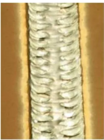
struc-Figure 11: Visual result after the final pass.
ture was observed after having welded several tens of meters. We now present some welding results. 4.4. Welding results
Welding is performed by defining a simultaneous control of the 2-degrees of freedom arm and the robot forward motion, in order to have a 3D trajec-tory of the welding torch. The trajectrajec-tory generation depends on the welding configuration (vertical or horizontal) and uses feedback from the joint profile measured by the laser scanner. The actual trajecto-ries of the welding torch are adapted from [18], they are not detailed due to confidentiality reasons. De-pending on the configuration being vertical or hor-izontal, the trajectories may correspond to a con-stant forward velocity of the mobile base, or some motionless time periods. Similarly, the arm motion may be constantly oscillating between two values that are extracted from the joint profile, or stay mo-tionless for some duration at particular positions. In order to ensure an optimal welding process, the vertical position control of the torch is regulated from the welding current feedback that varies posi-tively with the distance between the torch and the weld point. In practice the vertical position update is computed through a PID provided by the torch manufacturer.
The resulting process for vertical configuration is shown in Fig. 10. An interesting feature of the robot is that the joint profile is entirely scanned at each pass. Therefore, the complete evolution of the profile can be analyzed for process quality and optimization. Fig. 10a shows the complete 3D raw profiles for 10 welding passes of 1 m length. As dis-cussed in Section 2.1.4, laser scan aberrations are visible and are due to the welding light. They are
only a few peaks and can be filtered out. The high-level welding strategy is visible on Fig. 10b. Here 10 consecutive passes are represented using the mean profile along the joint. We can see that depending on the current profile, the welding strategy is to fill only a part of the joint. The final pass is wider and covers the whole joint, even if more material is dropped on the right part of the joint. This strat-egy is based on numerous exchanges and discussions with welders and previous work in [18]. The visual aspect of the final pass can be seen in Fig. 11. As expected, the weld is very regular along the joint, which helps the quality assessment of the process.
5. Conclusion
We have presented a new robot designed to per-form varying tasks on ship hulls. The mechanical design was exposed and is still being adapted to the latest experimental results. Compared to pre-vious works on wall-climbing robots, one objective of this project is also to prove that autonomous welding can be performed on long distances. To do so, a control law based on the laser feedback was designed and makes the robot autonomously weld several passes. As shown in Section 3.2, the per-formances in forward motion are accurate enough to track a reference trajectory. Another solution would be to use additional sensors but cameras are difficult to use during welding, and another laser scanner is not possible within the targeted price of the system. Future works on this project now focus on improving welding quality through bet-ter laser-based welding torch trajectories. To re-duce the twist effort on the chain, using two chains per track is also investigated. Inspection of weld-ing quality typically has to be done several hours after the welding [31], hence another mobile base may be equipped with inspection sensors while the welding robot works on another part of the hull. Finally, a strong limit of the prototype is of course that it is suited only for straight joints. However, ship builders currently spend most of their welding time on these joints. The proposed approach hence allows to automate this task while human welders cope with much more complex configurations.
Acknowledgements
This work was supported by the CHARMAN project managed by IRT Jules Verne (French In-stitute in Research and Technology in Advanced
Manufacturing Technologies for Composite, Metal-lic and Hybrid Structures). The authors wish to as-sociate the industrial and academic partners of this project, respectively, IRT Jules Verne, STX France, DCNS, Servisoud, LS2N and Bureau Veritas.
References
[1] M. F. Silva, J. T. Machado, J. K. Tar, A survey of technologies for climbing robots adhesion to surfaces, in: IEEE Int. Conf. on Computational Cybernetics, 2008, pp. 127–132.
[2] J. Savall, A. Avello, L. Briones, Two compact robots for remote inspection of hazardous areas in nuclear power plants, in: IEEE Int. Conf. on Robotics and Automa-tion, Vol. 3, 1999, pp. 1993–1998.
[3] T. Kang, H. Kim, T. Son, H. Choi, Design of quadruped walking and climbing robot, in: IEEE/RSJ Int. Conf. on Intelligent Robots and Systems, Vol. 1, 2003, pp. 619–624.
[4] R. Aravind Sekhar, A. Mary, S. Raju, A. Ravi, V. Sharma, G. Bala, A Novel Design Technique to De-velop a Low Cost and Highly Stable Wall Climbing Robot, in: 4th Int. Conf. on Intelligent Systems Mod-elling Simulation, 2013, pp. 360–363.
[5] B. E. Shores, M. A. Minor, Design, kinematic analysis, and quasi-steady control of a morphic rolling disk biped climbing robot, in: IEEE Int. Conf. on Robotics and Automation, 2005, pp. 2721–2726.
[6] M. A. Armada, P. G. de Santos, E. Garc´ıa, M. Prieto, S. Nabulsi, Design of mobile robots, in: Proc. of the 2005 CLAWAR: Introductory Mobile Robotics Work-shop, London, UK, 2005, pp. 2890–2895.
[7] K. Berns, C. Hillenbrand, T. Luksch, Climbing robots for commercial applications—a survey, in: Int. Conf. on Climbing and Walking Robots CLAWAR, 2003, pp. 17–19.
[8] S. Park, H. D. Jeong, Z. S. Lim, Design of a mo-bile robot system for automatic integrity evaluation of large size reservoirs and pipelines in industrial fields, in: IEEE/RSJ Int. Conf. on Intelligent Robots and Sys-tems, Vol. 3, 2003, pp. 2618–2623.
[9] W. Shen, J. Gu, Y. Shen, Proposed wall climbing robot with permanent magnetic tracks for inspecting oil tanks, in: IEEE Int. Conf. on Mechatronics and Au-tomation, Vol. 4, 2005, pp. 2072–2077.
[10] L. Wang, L. Graber, F. Iida, Large-payload climbing in complex vertical environments using thermoplastic adhesive bonds, IEEE Trans. on Robotics 29 (4) (2013) 863–874.
[11] M. P. Murphy, C. Kute, Y. Meng¨u¸c, M. Sitti, Waalbot II: adhesion recovery and improved performance of a climbing robot using fibrillar adhesives, Int. Journal of Robotics Research 30 (1) (2011) 118–133.
[12] M. Wu, X. Gao, Z. Fu, Y. Zhao, S. Chen, The mecha-nism design of a wheeled climbing welding robot with passing obstacles capability, Robotic Welding, Intelli-gence and Automation (2011) 401–409.
[13] M. Wu, G. Pan, T. Zhang, S. Chen, F. Zhuang, Z. Yan-zheng, Design and optimal research of a non-contact adjustable magnetic adhesion mechanism for a wall-climbing welding robot, Int. J. Adv Robotic Systems 10 (63).
[14] M. Bibuli, G. Bruzzone, G. Bruzzone, M. Caccia, M. Gi-acopelli, A. Petitti, E. Spirandelli, MARC: Magnetic autonomous robotic crawler development and exploita-tion in the MINOAS Project, in: Proc. 11th Interna-tional Conference on Computer and IT Applications in the Maritime Industries, COMPIT, Vol. 2012, 2012. [15] J. S´anchez, F. V´azquez, E. Paz, Machine Vision
Guid-ance System for a Modular Climbing Robot used in Shipbuilding, in: Climbing and Walking Robots, Springer Berlin Heidelberg, 2006, pp. 893–900. [16] H. Schempf, E. Mutschler, C. Piepgras, J.
War-wick, B. Chemel, S. Boehmke, W. Crowley, R. Fuchs, J. Guyot, Pandora: autonomous urban robotic recon-naissance system, in: IEEE Int. Conf. on Robotics and Automation, Vol. 3, 1999, pp. 2315–2321.
[17] A. T. Le, D. C. Rye, H. F. Durrant-Whyte, Estimation of track-soil interactions for autonomous tracked vehi-cles, in: IEEE Int. Conf. on Robotics and Automation, Vol. 2, 1997, pp. 1388–1393.
[18] J. Y. Hascoet, K. Hamilton, G. Carabin, M. Rauch, M. Alonso, E. Ares, Shiphull Welding: Trajectory Gen-eration Strategies Using a Retrofit Welding Robot, in: Materials Science Forum, Vol. 713, 2012, pp. 115–120. [19] C. Landry, M. Gerdts, R. Henrion, D. H¨omberg,
W. Welz, Collision-Free Path Planning of Welding Robots, in: Progress in Industrial Mathematics at ECMI 2012, Springer, 2014, pp. 251–256.
[20] H. N. M. Shah, M. Sulaiman, A. Z. Shukor, M. H. Ja-maluddin, M. Z. Ab Rashid, A Review Paper on Vision Based Identification, Detection and Tracking of Weld Seams Path in Welding Robot Environment, Modern Applied Science 10 (2) (2016) 83.
[21] N. Ku, S. Ha, M.-I. Roh, Design of controller for mobile robot in welding process of shipbuilding engineering, Journal of Computational Design and Engineering 1 (4) (2014) 243–255.
[22] D. Lee, Development of modularized airtight controller for mobile welding robot working in harsh environ-ments, Robotics and Computer-Integrated Manufactur-ing 29 (5) (2013) 410–417.
[23] A. Ismail, H. Ramli, M. Ahmad, M. Marhaban, Vision-based system for line following mobile robot, in: IEEE Symposium on Industrial Electronics & Applications, Vol. 2, 2009, pp. 642–645.
[24] D. Gu, H. Hu, Receding horizon tracking control of wheeled mobile robots, IEEE Trans. on control systems technology 14 (4) (2006) 743–749.
[25] A. Savitzky, M. J. E. Golay, Smoothing and Differenti-ation of Data by Simplified Least Squares Procedures., Analytical Chemistry 36 (8) (1964) 1627–1639. [26] H. Thiel, A rank-invariant method of linear and
polyno-mial regression analysis, Part 3, in: Proceedings of Kon-inalijke Nederlandse Akademie van Weinenschatpen A, Vol. 53, 1950, pp. 1397–1412.
[27] M. Dinham, G. Fang, Detection of fillet weld joints us-ing an adaptive line growus-ing algorithm for robotic arc welding, Robotics and Computer-Integrated Manufac-turing 30 (3) (2014) 229–243.
[28] H. N. M. Shah, M. Sulaiman, A. Z. Shukor, Z. Kamis, A. Ab Rahman, Butt welding joints recognition and location identification by using local thresholding, Robotics and Computer-Integrated Manufacturing 51 (2018) 181–188.
[29] L. Consolini, F. Morbidi, D. Prattichizzo, M. Tosques, Stabilization of a hierarchical formation of unicycle
robots with velocity and curvature constraints, IEEE Trans. on Robotics 25 (5) (2009) 1176–1184.
[30] S. J. Julier, J. K. Uhlmann, A new extension of the Kalman filter to nonlinear systems, in: Int. symp. aerospace/defense sensing, simul. and controls, Vol. 3, 1997, pp. 182–193.
[31] K. Weman, Welding processes handbook, Elsevier, 2011.