AVIS
Ce document a été numérisé par la Division de la gestion des documents et des archives de l’Université de Montréal.
L’auteur a autorisé l’Université de Montréal à reproduire et diffuser, en totalité ou en partie, par quelque moyen que ce soit et sur quelque support que ce soit, et exclusivement à des fins non lucratives d’enseignement et de recherche, des copies de ce mémoire ou de cette thèse.
L’auteur et les coauteurs le cas échéant conservent la propriété du droit d’auteur et des droits moraux qui protègent ce document. Ni la thèse ou le mémoire, ni des extraits substantiels de ce document, ne doivent être imprimés ou autrement reproduits sans l’autorisation de l’auteur.
Afin de se conformer à la Loi canadienne sur la protection des renseignements personnels, quelques formulaires secondaires, coordonnées ou signatures intégrées au texte ont pu être enlevés de ce document. Bien que cela ait pu affecter la pagination, il n’y a aucun contenu manquant.
NOTICE
This document was digitized by the Records Management & Archives Division of Université de Montréal.
The author of this thesis or dissertation has granted a nonexclusive license allowing Université de Montréal to reproduce and publish the document, in part or in whole, and in any format, solely for noncommercial educational and research purposes.
The author and co-authors if applicable retain copyright ownership and moral rights in this document. Neither the whole thesis or dissertation, nor substantial extracts from it, may be printed or otherwise reproduced without the author’s permission.
In compliance with the Canadian Privacy Act some supporting forms, contact information or signatures may have been removed from the document. While this may affect the document page count, it does not represent any loss of content from the document.
Identification of Behavioral and Creational Design Patterns through Dynamic Analysis
par
Janice Ka-Yee Ng
Département d'informatique et de recherche opérationnelle Faculté des arts et des sciences
Mémoire présenté à la Faculté des études supérieures en vue de l'obtention du grade de Maître ès sciences (M.Sc.)
en informatique
Avril, 2008
Faculté des études supérieures
Ce mémoire intitulé:
Identification of Behavioral and Creational Design Patterns through Dynamic Analysis
présenté par:
Janice Ka-Yee Ng
a été évalué par un jury composé des personnes suivantes:
Pierre Poulin président-rapporteur Yann-Gaël Guéhéneuc directeur de recherche Julie Vachon membre du jury Mémoire accepté le
Les patrons de conception proposent une solution à la fois simple et élégante aux problèmes récurrents en programmation orientée objet lors de l'implantation des programmes, car ils contribuent à améliorer la conception. Cependant, à l'usage, ces patrons sont disséminés dans le code source des programmes et, par conséquent, ne sont plus disponibles au moment de la maintenance. Pourtant, ils aideraient à comprendre leur implantation et conception, et à assurer la qualité des programmes après la maintenance.
Dans les travaux antérieurs, la structure et l'organisation des classes servent principalement de source de données pour l'identification des occurrences de pa-trons de conception. Il est toutefois intéressant de considérer la responsabilité des objets participant à l'exécution des programmes, puisque deux types de patrons de conception (comportementaux et créationnels) se caractérisent principalement par la distribution des responsabilités et la collaboration entre les objets à l'exécution. Ce mémoire propose un méta-modèle et des algorithmes pour identifier auto-matiquement des occurrences de patrons comportementaux et créationnels dans le code source. Nous utilisons la méta-modélisation pour décrire les patrons de concep-tion et les programmes Java, et l'analyse dynamique pour capturer le comporte-ment des programmes au mocomporte-ment de l'exécution. La méta-modélisation permet d'expliciter la collaboration entre les participants impliqués dans l'exécution d'un programme (les messages) et de préciser leurs propriétés (condition d'exécution d'un message, répétition d'un message). Enfin, elle conduit à traduire les patrons en systèmes de contraintes avec explications et à identifier les occurrences similaires, formes complètes et approchées, par la résolution de problèmes de satisfaction de contraintes.
Mots clés: identification de patrons de conception, analyse dyna-mique, diagrammes de scénarios, programmation par contraintes, rétro-conception.
The use of design patterns is a simple and elegant way to solve problems when designing object-oriented software systems because it leads to well-structured de-signs. However, after application, design patterns are lost in the source code, and are thus of litt le help during program comprehension and subsequent maintenance. In previous work, the structure and organization among classes were the pre-dominant source of data used for the identification of occurrences of design pat-terns. Yet, the responsibility of each participating object at runtime should not be neglected, as two types of design patterns, behavioral and creational, are mainly concerned with the assignment of responsibilities and the collaboration among ob-jects at runtime.
This thesis proposes a metamodel and algorithms to automatically identify be-havioral and creational design patterns in the source code. We use metamodelling to describe design patterns and software systems in Java, and dynamic analysis to capture the behavior of the systems at the moment of execution. The proposed metamodel allows the representation of interactions among the participants that take part in the execution of a system (messages) and their properties (conditions under which a message is executed, repetition of a message). Using this metamodel, the problem of behavioral and creational pattern identification can be translated into an explanation-based constraint satisfaction problem. Solving such kind of problems leads to exact or approximate occurrences of a design pattern.
Keywords: design pattern identification, dynamic analysis, scenario diagram, constraint programming, reverse engineering.
RÉSUMÉ iii
ABSTRACT iv
CONTENTS . . . . v
LIST OF TABLES. viii
LIST OF FIGURES. ix
LIST OF ALGORITHMS xi
LIST OF APPENDICES. . . xii
LIST OF ABBREVIATIONS xiii
NOTATION .. xiv
DEDICATION . . . .. xv
ACKNOWLEDGEMENTS xvi
CHAPTER 1: INTRODUCTION 1
1.1 Context: Reverse Engineering and Design Patterns 1 1.2 Motivations: Identification of Behavioral and Creational Patterns 1
1.3 Contributions 2
1.4 Outline.... 5
CHAPTER 2: RELATED WORK 6
2.1 Structural Pattern Identification. 7
2.2 Dynamic Data for the Identification of Patterns 9 2.3 Recovery of Sequence Diagrams . . . 12
2.4 C o n c l u s i o n . . . 16
CHAPTER 3: SCENARIO DIAGRAM AND DESIGN PATTERN DESCRIPTION . . .
3.1 Scenario Diagram Notation and Metamodel 3.2 Modelling Behavioral and Creational Patterns
3.2.1 Builder .. 3.2.2 Command 3.2.3 Memento 3.2.4 Observer. 3.2.5 Visitor 3.3 Conclusion. .
CHAPTER 4: REVERSE ENGINEERING OF SCENARIO DIA-GRAMS . . . .
4.1 Reverse Engineering Technique Using Dynamic Analysis 4.1.1 Format of the Execution Trace
4.1.2 Instrumentation . . . . 4.1.3 Instantiation of Scenario Diagram .
20 20 23 24 25 26 27 29 30 31 31 33 34 40 4.2 C o n c l u s i o n . . . 41
CHAPTER 5: IDENTIFICATION OF DESIGN PATTERNS. 42
5.1 Explanation-based Constraint-Programming 42
5.1.1 Explanations . . . . 5.1.2 Computing Explanations . 5.1.3 Using Explanations . . . .
5.2 Application to the Problem of Design Pattern Identification 5.2.1 A Library of Specialized Constraints
5.2.2 Solver 5.3 Conclusion.. 43 44 44 46 48 53 54
CHAPTER 6: EVALUATION.
6.1 JHotDraw Case Study . . .
6.1.1 Step 1: Description of the Visitor Pattern
6.1.2 Step 2: Reverse Engineering of Scenario Diagram 6.1.3 Step 3: Constraint Satisfaction Problem
6.2 Accuracy on Several Systems 6.3 Threats to Validity . . . 6.3.1 InternaI Validity 6.3.2 External Validity 6.4 Conclusion... 56 56 56 57 58 60 63 64 64 67 CHAPTER 7: CONCLUSION . . . 68 BIBLIOGRAPHY . . . .. 70
6.1 Precision and recall calculated on particular scenarios of software systems for which the uses of design patterns are known. . . .. 61
Class diagram notation . . . Sequence diagram notation .
1.1 A 3-step approach for the identification of design patterns through xiv xiv
dynamic analysis . . . .. 3
2.1 The Composite pattern described as Prolog facts and rules by Wuyts [Wuy98] . . . 8 2.2 A design pattern metamodel proposed by Guéhéneuc et al. [GJ01] 9 2.3 Structural representation of the Decorator pattern by Tsantalis et
al. [TCSH06] . . . 10 2.4 The Observer pattern described statically by Heuzeroth et al. [HLM03] 11 2.5 Validation of the behavior of methods by Heuzeroth et al. [HLM03] 11 2.6 Canonical four-dimensional event space by De Pauw et al. [PKV94] 13 2.7 Inter-class calI cluster by De Pauw et al. [PKV94] 14 2.8 Inter-class calI matrix by De Pauw et al. [PKV94] 15 2.9 Histogram of instances by De Pauw et al. [PKV94] 15 2.10 CFG for a method m and its corresponding reverse engineered
sce-nario diagram by Routnev et al. [RVR05] . . . 16 2.11 Scenario diagram metamodel by Briand et al. [BLM03] 17 2.12 Execution trace metamodel by Briand et al. [BLM03] . 17 2.13 Consistency rules for the mapping between two metamodels by Briand
et al. [BLM03] . . . 18
3.1 Scenario diagram metamodel . 21
3.2 Scenario diagram notation .. 22
3.3 Description of the Builder pattern in terms of collaboration 25 3.4 Description of the Command pattern in ter ms of collaboration 26 3.5 Description of the Memento pattern in terms of collaboration . 27
3.6 Description of the Observer pattern in terms of collaboration 28 3.7 Description of the Visitor pattern in terms of collaboration . 29
4.1 Execution trace of a toy system implementing the Memento pattern 35 4.2 Partial source code of class Memento . . . 36 4.3 Constructor bytecode before instrumentation . 36
4.4 Constructor bytecode after instrumentation 36
4.5 Source code of class TestRepeti tion. . . 38 4.6 Bytecode of method main (String []) before instrumentation. 38 4.7 Bytecode of method main (String []) after instrumentation. 39 4.8 Textual representation of the scenario diagram after that the
execu-tion trace of Figure 4.1 has been processed . . . . 40
1 Constraint caller(classifier1, message2) (respectively callee) 49 2 Constraint creator (classifier1, message2) (respectively
cre-ated). . . 51
3 Constraint follows(message1, message2) 51
BCEL CSP eCSP JIKES RVM OCL UML
Byte Code Engineering Library Constraint Satisfaction Problem
Constraint Satisfaction Problem with Explanations
JIKES Research Virtual Machine
Object Constraint Language U nified Modelling Language
t
li CDncreleSubcl-:.!
Class diagram notation
~=-.~~~.,---1 o anolherObh~C1 : Oblect ~ ... ~ .. .
·1
'---~--"" 1First, 1 would like to express my sin cere gratitude to my greatly appreciated super-visor, Yann-Gaël Guéhéneuc, for giving me the chance to accomplish such a signifi-cant project, and supporting me unconditionally all along my studies. 1 would not have make it through without your sound advice! AIso, 1 would like to say thank you to each and every member of the GEODES team who contributed directly or indirectly to the success of my graduate studies. In particular, thank you the valuable professors of the team, Houari Sahraoui, Julie Vachon, and Petko Valt-chev, whose words of wisdom are my source of inspiration. Moreover, thank you to Gerardo Cepeda, Simon Denier, Karim Dhambri, Sébastien Jeanmart, Foutse Khomh, Guillaume Langelier, Naouel Moha, Viet Thang Pham, Yousra Tagmouti, and Stephane Vaucher, with whom 1 had amusing discussions in the so-caIled 'salle-qu'il-ne-faut-pas-nommer' pantry, and above aIl, who made my life greedier than ever thanks to our regular visits to tasteful restaurants. U ndeniably, 1 gained a few pounds with aIl those exquisite meals. However, 1 shared so many pleasant moments with the team !
Furthermore, 1 would like to express my deepest gratitude to Guillaume Ra-berge, who walked beside me since the beginning of my graduate studies, and believed in me under any circumstances. Your words of encouragement and perse-verance inspired me to achieve passionately and assiduously my project. Without you, the road to graduation would have seem much more longer. Thank you for bearing with the unbearable me aIl these years !
m1~
,
~::fm::ffm-i:~m)L\~~3t~~~~Â 0 ftÈ1r~~tf1f~~1f~~~~aql1.J1J 0 ~~ , ~~1ff\:@:M$~*aq~JL\~:l:ti~~!~J:.aq3tfl: ' ~::f~~m.*Yi
~M1J*~:@:m.wo • • '.~~~~.XH~X~~~.o ' • • ~
mmsend~1~*~IIIJ~ 0 *~J3.
' ••
1ff\~~JHJ~Mlf.®~ ,W~~~ 1i!~!tliiMIMo~ffl'~~~li~m~.'~*~w~m~1f.~MoYi~~~~rr.~M ~3t.':@:.~~::f~M*~~o~~~m.~!
INTRODUCTION
1.1 Context: Reverse Engineering and Design Patterns
Software maintenance is a crucial phase of the software development process, as it consumes as mu ch as 90% of the total resources dedicated to a software system [ErlOO]. The main activity during maintenance is program comprehension, during which maintainers analyze the structure and organization of code artifacts with the help of re-engineering tools, to perform maintenance tasks such as debugging or adding new features. The recovery of the design and architecture is relevant to the maintainers, as they provide insights on the original choices made during the initial phase of conception.
Since their inception in 1994, design patterns [GHJY94] have been increasingly used to design and obtain well-structured systems. Design patterns are solutions to recurrent problems in object-oriented systems. Their recovery during the main-tenance should consequently make the task easier. However, in reality, design patterns are lost in the source code of the systems due to their complexity and lack of documentation. It is difficult or impossible to manually recover design pat-terns applied during system design and implementation, which impedes program comprehension and increases the cost of its maintenance [ACdPF01].
1.2 Motivations: Identification of Behavioral and Creational Patterns While organizing the catalog of design patterns, Gamma et al. [GHJY94] divided their patterns into three families of related patterns. Following the criterion of
pur-pose, which indicates what the pattern does, patterns can either have a structural, behavioral, or creational purpose (cf Annexe 1 for the classification). Structural patterns deal with the organizationjcomposition of classes or objects. Behavioral
patterns characterize the ways in which objects interact and share responsibility. Creational patterns are concerned with object creation.
Several approaches have been proposed to identify design patterns in source code using static analysis, for example [KP96,SvG98,Wuy98,KSRP99,Nie02,PL06, TCSH06]. The fundamental idea of these approaches consists in analyzing the class structure of a system to identify micro-architectures that are similar to the known structure of a design pattern. These approaches are limited when recovering pure behavioral and creational patterns because the responsibilities and the collabora-tion among objects at runtime cannot be easily and completely determined using static analysis. Moreover, behavioral and creational design patterns can hardly be described only by their structure.
Thus, to provide a better view of the system to be reverse engineered, previous work suggested to combine static and dynamic analyses, because the dynamic as-pect can provide data to complement those related to the structure of a system (as shown in [HHL02,HLM03]). First, static analysis is performed to find pattern can-didates that have the structure of the searched pattern; then, dynamic analysis is conducted to remove false positives, and thus to confirm pattern candidates. How-ever, the limitation still remains: behavioral and creational patterns, which cannot aIl be uniquely identified by structural means, risk not to be recovered during static analysis.
Therefore, in this thesis, we propose a pure dynamic approach that directly analyzes the collaboration among objects by making use of dynamic analysis for the recovery of behavioral and creational patterns.
1.3 Contributions
Although the domain of design pattern identification is well-established, we contribute to this domain with an approach that identifies behavioral and creational design patterns. Using existing sequence diagram recovery and explanation-based constraint programming techniques, our approach can identify pure behavioral and
Design Pattern (Source f - - - " - - - - > I System)
(2)
Identlfied Design Patterns ln Target Scenario DlagramCONSTRAINT SATISFACTION PROBLEM Source Scenario Dlagram Target Scenario Dlagram 00 Software (Target System)
REVERSE ENGINEERING OF SCENARIO DIAGRAM
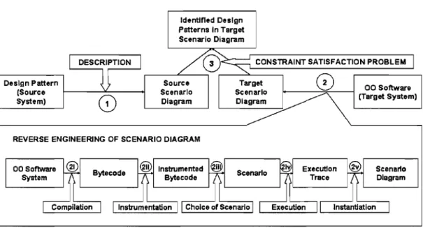
Figure 1.1: A 3-step approach for the identification of design patterns through dynamic analysis
creational patterns, unlike other previous work which focused on structural patterns recovery.
We propose a 3-step approach (as illustrated in Figure 1.1, Steps 1, 2, and 3) to identify behavioral and creational design patterns in source code using dynamic analysis. First, we describe behavioral and creational patterns in terms of UML-like sequence diagrams. In our approach, UML sequence diagrams are obtained from the execution of a use case. Therefore, these diagrams will be referred to as
scenario diagrams in the rest of this thesis: they are only partial UML sequence diagrams describing one scenario corresponding to a use case, instead of aIl possible alternatives for the exercised use case [BLL06].
Second, using dynamic analysis, we reverse engineer a dynamic model-again, in the form of scenario diagrams-of the collaboration among objects of a sys-tem for a given scenario. In this context, we are interested in discovering the exact collaboration among runtime objects to find real occurrences of a design pattern (as opposed to potential ones). Therefore, we favored dynamic analysis
over static analysis to obtain dynamic data. Previous work (even the currently most powerful ones [RC05]) showed that interaction diagrams, such as UML col-laboration or scenario diagrams generated from static analysis, result in possi-bly highly inaccurate diagrams and, in the worst case, describe impossible behav-iars, depending on the technique used to determine object references in the source code [TP03, RC05, RVR05]. Furthermore, it is not conceivable for any large, com-plex systems to perform coarse-grained and sophisticated analysis of the source code to determine the dynamic types of object references [GJM91]. In contrast, dynamic ânalysis is more accurate because it reports precisely the interactions be-tween objects without symbolic representation. By tracing the execution of a use case, we easily obtain data that can be used to reverse engineer a scenario diagram. However, its main limitation is that it depends on the executed scenario. We plan to address, in future work, the building of a complete sequence diagram for a given use case from a set of scenario diagrams. This building requires triggering as many scenarios as possible through multiple executions of a system, and their analysis to merge them into one sequence diagram.
Finally, as in previous work [GAAOl], we translate the problem of design pat-tern identification into a constraint satisfaction problem with explanations (eCSP), which consists in assigning concrete objects and messages from the scenario dia-gram of the executed scenario, to the roles in the scenario diadia-gram of a design pattern. Solving the eCSP consists in matching, one against the other, the objects and messages of the scenario diagram of a design pattern with the ones of the executed scenario. We chose to use explanation-based constraint programming to solve the problem of pattern identification because it allows both the identification of complete and approximate occurrences of design patterns, and allows interaction guidance.
We can resume the contributions of this thesis in the following points:
• An approach to automatically identify pure behavioral and creation al design patterns through dynamic analysis;
• A technique based on metamodelling and intermediate code instrumentation to reverse engineer the scenario diagrams of an object-oriented system; • The building of a library of specialized constraints to describe the
collabora-tion among objects in terms of concepts introduced by our scenario diagram metamodel.
Last but not least, we had the opportunity to publish the results of our research in [NG07].
Hypothesis
Using dynamic analysis, is it possible to identify behavioral and creational de-sign patterns in object-oriented software systems?
1.4 Outline
This thesis is structured as follows: Chapter 2 presents the related work. Chap-ter 3 introduces our metamodel to capture the collaboration among objects at runtime. This metamodel is similar to the UML metamodel for scenario diagrams.
It is used to describe behavioral and creational design patterns, as weIl as scenario diagrams from any scenario of a system. Chapter 4 describes our technique to re-verse engineer sequence diagrams of an object-oriented system. Chapter 5 presents the technique used to identify behavioral and creational design patterns. Chap-ter 6 illustrates our identification approach using one scenario of JHOTDRAW, a drawing editor for technical and structured graphics, then reports results related to the identification of the Builder, Command, and Visitor patterns in five systems, and finally discusses the approach. We conclude and present future work in Chapter 7.
RELATED WORK
The identification of design patterns in object-oriented systems has been the subject of many work. In particular, the identification of structural design patterns has been investigated as early as 1998 (Wuy981. However, we are not aware of work dedicated to the identification of behavioral and creational patterns (without any structural data). Thus, we present work related to the identification of structural design patterns in Section 2.1, and to the use of dynamic data during structural design pattern identification in Section 2.2. These identification approaches are compared one against the other according to the following criteria:
• The types of recovered design patterns (structural, behavioral, and creational); • The possibility to get explanations on the obtained occurrences;
• The degree of automation of the identification technique;
• The accuracy of the precision and recall measures of the identification tech-nique;
• The performance of the identification technique;
• The ability to deal with variants/approximations of the design patterns. The necessity for identification approaches to de al with variants/approximations of patterns originates from the fact that the implementation of a design pattern in most systems, although true to their original intention in [GHJV94], does not always strictly match the solution as described in theory. In this chapter, we explore the different techniques of pattern identification in this respect, among others. Finally, we dedicate Section 2.3 to work related to the recovery of sequence diagrams, providing guidance for our own reverse engineering approach of scenario diagrams.
2.1 Structural Pattern Identification
Since their inception in 1994, design patterns have been the subject of many work related to their recovery in software systems. We present here four char ac-teristic contributions that aIl use static data, but distinguish themselves by their identification technique: Prolog, queries, eCSP, and matrices similarity.
For example, Wuyts [Wuy98] published a precursor work on structural design pattern identification. His approach consisted in representing object-oriented sys-tems as Prolog facts and predicates: facts describe the structure of object-oriented systems, such as inheritance and acquaintance relations, while predicates are used to formulate queries for reasoning about facts and to identify occurrences of design patterns.
Facts were extracted using static analysis. The Composite pattern is expressed manually using the predicates depicted in Figure 2.1. Briefly, a composite pattern consists in the definition of a certain structural relationship between the variables of component ?comp and composite ?composi te. Also, there is an aggregation relationship between these two. The composi teStructure rule defines that ?comp is a class, and that ?composi te is a subclass, direct or indirect, from the compos-ite. The composi teAggregation predicate expresses that the composite should override at least one method of the component, and in this overridden method, it should do an enumeration over the instance variable that holds these composites and recursively apply the method ?msg to each of the composites. This approach had performance limitations due to the use of a Prolog engine. It could not deal with variants automatically, and showed limited precision and recall according to subsequent studies.
This previous work was followed by many other approaches to improve on its performances. These following approaches use different data and different represen-tation and detection techniques. For example, Quilici et al. [QYW97] established a relationship between plan recognition and program comprehension. Plan recog-nition makes use of structural events and actions to determine "the best unified
context which causally explains a set of perceived events as they are observed". The authors derived a new approach to program plan recognition by augmenting exist-ing AI plan recognition algorithms. In particular, their experimentations check the presence of instances of a given plan in the system source code using constraint pro-gramming, while improving the performance of plan recognition. However, poor performances are again an issue: results show that constraint checks, i.e., their measure of efficiency, deteriorates with the number of lines of code.
Guéhéneuc et al. [GJOl] drew inspiration from previous work to propose an approach for structural design pattern identification. This problem is represented as a constraint satisfaction problem, for which the authors introduced the use of explanation-based constraint programming, and a dedicated metamodel capturing structural representation of both design patterns and systems [AAG01] as depicted in Figure 2.2. It includes the modelling of binary class relationships such as associa-tions, aggregaassocia-tions, and compositions [GAA04] to improve both the representation and the handling of variants.
Recently, Tsantalis et al. [TCSH06] introduced a measure of similarity between matrices representing either systems or patterns to improve performance and deal with a wide range of structural design patterns, as weIl as their modified versions.
RULE RULE head: compositePatternC?comp,?composite,?msg) body: compositeStructureC?comp,?composite) compositeAggregationC?comp,?composite,?msg) head: compositeStructure(?comp,?composite) body: class(?comp) hierarchy(?comp,?composite) RULE head: compositeAggregation(?comp,?composite,?msg) body: commonMethods(?comp,?composite,?M,?compositeM) methodSelector(?compositeM,?msg) oneToManyStatement(?compositeM,?instVar,?enumStatement) containsSend(?enumStatement,?msg)
rranom trospoctor
F
siiVOr]1 1 1
l 1 - - 1
targetAssoc:
1
Figure 2.2: A design pattern metamodel proposed by Guéhéneuc et al. [GJOl]
The structure of systems or patterns is modelled using matrices, because the au-thors consider that a class diagram is fundamentally "a directed graph that can
be perfectly mapped into a square matrix". Each kind of information such as as-sociations, generalizations, abstract classes, object creations, or abstract method invocations is represented in an individual graphjmatrix. Figure 2.3 shows such a representation for the Decorator pattern.
2.2 Dynamic Data for the Identification of Patterns
Sorne work suggested to improve the precision and recall of previous approaches by combining static and dynamic identifications.
For instance, Heuzeroth et al. [HLM03] proposed an approach that uses both static and dynamic data to identify interaction patterns. On the one hand, the static specification of a pattern is a collection of Prolog predicates that describe the relations between the elements, as illustrated in Figure 2.4. On the other hand, the dynamic aspect is also represented by Prolog predicates, following the tempo-ral logic of actions. Static analysis of the system source code is performed under the form of Prolog query corresponding to the static predicates, to suggest a set
Association G<aph Assodation lIatrhl.
Ci
Ib/
~o
b --
~Ctrl~OOOO_[0 0 0 0]
o.znar , 0 0 00== ~ 0 0 0 0
Generallzatlon Graph GenerallzaUon Matrlx
AbstnIct ete ... Grlph Abab1lct Clau . . Matrb:
~o Ç()"""""'" _ [ '
Ib/
0
00-. 00-. 00-. CtrlO'llte~ 0 0 0 0
o.:-.br 0 0 1 0
0:::. c..r.:.~ 0 0 0 0
Slmllar Abstract Method Invocation SIm1Iar Abstracl Method Invocation
= 0 \ -
--=[r1(
Qg::: ~.u. 0 0 0 0
Figure 2.3: Structural representation of the Decorator pattern by Tsantalis et al.
[TCSH06]
of candidate pattern instances conforming to the static structure of the searched pattern. Then, dynamic analysis monitors the execution of the candidates, and validates their behavior according to the dynamic specifications of the searched pattern, as shown in Figure 2.5. Finally, a dedicated validator confirms or rejects the candidates. The proposed approach was exemplified with the Observer,
Com-posite, and Decorator patterns, and evaluated on their own analysis tool system.
However, the authors did not provide details about the measures of precision and recall. It is therefore difficult to determine the impact of false negatives omitted during the static analysis on the results of the experimentations, and possible
al-observer(Vattach. Vattachee. Vdetach. Vdeteachee. Vlistener, Vnotify, Vsubject,
Vupdate):-listener(Vlistener. Vupdate),
subject(Vattach, Vattachee, Vdetatch. Vdetachee, Vlistener, Vnotify, Vsubject, Vupdate).
subject(Vattach, Vattachee, Vdetach, Vdetachee, Vlistener, Vnotify, Vsubject,
Vupdate):-notify(Vnotify, Vsujbect, Vupdate),
attach(Vattach, Vattachee, Vlistener, Vsubject), detach(Vdetach, Vdetachee, .Vlistener, Vsubject), class(Vsjubect).
attach(Vattach, Vattachee, Vlistener, Vsujbect):-attachee(Vattachee, Vlistener). assignAttachee(Vattachee, Vstatement15), member(Vattach. Vsubject). method(Vattach), parameter(Vattachee, Vattach), statement(Vstatement15, Vattach
Figure 2.4: The Observer pattern described statically by Heuzeroth et al. [HLM03]
watch('attach', Vattach, Arguments):-observer (Vattach, Vattachee. _, _, Arguments = ['this', Vattachee].
onMethodEntry('attach', Vattach, [Vsubject, Vattachee]):-dynamicConformTyped(Vattachee. VattacheeClass), containingTyped(VattacheeName, VattacheeClass). dynamicConformTyped(Vsubject. VsubjectClass),
dynamicObserver(VNo, Vattach, VattacheeName, _. _. VsubjectClass, _), request(assert(attached(VNo, Vsubject, Vattachee))),
fail.
Figure 2.5: Validation of the behavior of methods by Heuzeroth et al. [HLM03]
ternatives to deal with. AIso, it is unclear how this approach can be generalized to pure behavioral and creational design patterns. Finally, as the proposed approach uses a Prolog engine for querying facts, it had the same performance limitations as Wuyts.
Shawky et al. [SAEHES05] proposed a similar approach to improve the preci-sion and recall of a static identification approach. During the static analysis that determines the pattern candidates fulfilling the static characteristics of a pattern,
the authors introduced two constraints, i.e., a method delegation constraint and a key method constraint, to reduce the number of pattern candidates that the dynamic analysis must validate. On the one hand, the method delegation con-straint statically checks for specifie method invocations. On the other hand, the key method constraint checks whether the objective and behavior of a pattern at runtime are fulfilled. Only pattern candidates satisfying the aforementioned static constraints are provided as inputs to the dynamic analysis. However, it is unclear which dynamic constraints a pattern candidate should satisfy to be validated. AIso, this approach uses a customized debugger to manuaIly inspect the dynamic behav-ior of a key method, which decreases considerably the degree of automation of its dynamic analysis.
Most of the previous work on the identification of structural design patterns uses data related to method caIls, which can be considered as dynamic data. For exam-pIe, Antoniol et al. [ACdPF01] used delegation constraints to further reduce the set of pattern candidates satisfying the structural specification of a design pattern. Guéhéneuc et al. [GJ01], as mentioned in the previous section, recovered, among other binary relationships, composition relationships between classes [GAA04] by tracing three specifie events when a system is executed: assignment events, finalize events, and system-end events.
2.3 Recovery of Sequence Diagrams
The recovery of scenario diagrams has been tackled by several authors. An important contribution to this domain is the work of De Pauw et al. [PKV94], which describes a model to visualize data about the execution of object-oriented systems. In representing the dynamic behavior of the systems, the authors have chosen to use a canonical four-dimensional event space to conceptually model object construction and destruction, and method invocation and return, as illustrated in Figure 2.6. Each point in the space is described by the coordinate quadruple (class, instance, method, time), and corresponds to an event during system execution.
classes
Figure 2.6: Canonical four-dimensional event space by De Pauw et al. [PKV94]
However, the implementation of such a model is impractical, as a typical system can generate many hundreds of thousands of construction, destruction, enter, and leave events. To overcome this limitation, the authors made a correlation between this event space and the notion of call frames to store combinat ions of events, to ensure that execution data is stored compactly and information retrieval is efficient. From there on, users can navigate and visualize the event space respectively using queries and the proposed visualizing tool, allowing the exploration of the different perspectives, as illustrated in Figures 2.7, 2.8, and 2.9. On the one hand, the inter-class calI cluster provides a dynamic overview of communication patterns between classes. On the other hand, the inter-class calI matrix gives cumulative and more quantitative information. FinalIy, the histogram of instances displays aIl instances of each class. Later, in 2002, De Pauw et al. [P JM+02] designed a tool to visualize many facets of system behavior. In particular, a technique for pattern extraction is proposed to simplify the views by eliminating repetitions of messages. However, it is not clear whether a detected repetition of messages distinguishes the execution of a loop from the incidental execution of identical method sequences in different contexts.
Rountev et al. [RVR05] described a first algorithm to reverse engineer UML 2.0 sequence diagrams by control-ftow analysis of Java code. One of their objectives was to represent the intraprocedural behavior of the systems, such as conditional and
·SolulfOrï' b1Vlub1eiU'
-*,!I!Mi!"jj'''~'''.!llj''!IIill!llm'!!lfI!!!II!IIIIJ!!U"mJJ[JJJTJJIJW
Figure 2.7: Inter-class call cluster by De Pauw et al. [PKV94]
iterative behaviors, in the reverse engineered sequence diagram. As a result, they extended UML 2.0 by generalizing the break fragment to allow breaking out multiple enclosing fragments and by defining the return fragment to model multiple exit nodes. For each method qf a system, the approach transforms its control flow graph into a partial sequence diagram. Then, a single multi-method diagram is generated by combining these partial diagrams. Figure 2.10 shows such a transformation. Their approach does not consider data obtained by dynamic analysis, and thus solely depends on the accuracy of the control-flow analysis.
Briand et al. [BLM03] proposed a method to reverse engineer scenario diagrams from execution traces. In particular, they proposed two metamodels, one describing
•
•
••
••••
•
•
••
•
•••
•
•
•
•
•
••
•
•
•
C'l•
••
••
• •
•
•
•
•••
•
•
•
••
••
•
"mUnUIfIUllltflMl'+"II1Ullllllillllll"UlfllllillllllllllillmUIIUIUIltilFigure 2.8: Inter-class caU matrix by De Pauw et al. [PKV94]
.
..
...
= q - ) ... :-=.: ......
--
...
...
_
-......
...
~...
_ -I,~~=~=~... -_ ...
I! - : _~_..:::t_
... _..
...
--
...
_---
... ....
- J - . . -...
:...
_WhI IlIIIJU 1111 IIIllIyMUIi III 1J!IIIJOli 1 1111If!1II1!1I111Il 1111 1 OlllllllllllllllliiJ
1 311 [c7) m6() - - - F-,----[k:7]
rm9()
I~I 1 1T
1~
1Figure 2.10: CFG for a method m and its corresponding reverse engineered scenario
diagram by Routnev et al. [RVR05]
scenario diagrams, and the other describing execution traces. A mapping estab-Iished between the two metamodels, illustrated by Figures 2.11 and 2.12, defines how to derive a scenario diagram from a recovered execution trace. This mapping is defined by a set of consistency rules in OeL, like the ones shown on Figure 2.13. Later, in 2006, Briand et al. [BLL06] introduced a complete approach to recover scenario diagrams using execution traces. Their work inspired our own recovery approach.
2.4 Conclusion
In this chapter, we covered related work of three important fields that inspired our behavioral and creational pattern identification approach. First, we presented work on structural pattern identification. Second, we reviewed approaches that
0 .. 1 . Message
-OOjecllD: Int -nodaID: inl
~
-signature: String~ -ijmestampSourœ: lm
foliowingMessages i -timestampOest Int
' - - - ' (ordered) II
y
Destroy 1 Create
Figure 2.11: Scenario diagram metamodel by Briand et al. [BLM03]
nestedStatemen! ,----_ _ _ _ _ _ --,
{Ofdefed} ExecutionStatement
o.,'
-slalement: Slring
'--_ _ 0_,,1-.1 4imeslamp: in!
r----;:--"---::--" nestingStatement -nodalD: int
.-_ _ ~ ____ --,tfgg~s MethodExecutlon O ... clause -clause :Stfing~n Repetition _ ... ' -kind: RepelitionKind -forLoopVar. String 0,,' -forLooplnc Strin Instance context 1.: 1 «enumeratlon:» RepelltlonKind for white doWhOe callee {ordered} '--""~_--' -isCreata: boolean -isDestro : boolean
1 methodCall. alllnotanooo->forAll (ml. m2: MethodCall 1 ml. callee->inoludoo (m2) 2 impliell
3 rnethodMeooage.alllnotancoo->oxioto(mm:MethodMeooage 4 mm. content = m2 .. statement
5 and
6 if ml.context.ocIType a InotanceTRACE thon ( 1/ checking the caller 7 mm.callerObject.addrecoID aml.context.id and
a mm.callerObject.theClaoo.narne a rn1.context.theClaos.name
9 .. 100 (
10 mm.callerObject.narne = rn1.context.name
11
12 and
13 if .m2.context.ocIType a InotanceTRACE th .. n ( Il check~ng the callee 14 mm.calleeObject.addreooID = m2.context.id and
15 mm.calleeObject.theClaco.name a m2.context.theClaoo.name
16 0100 (
17 mm.calleeObject.name a rn2.context.name
la 19 and
20 mm.returnType a m2.returnType and
21 mm.pararneterSEQD->forAll(index:lnteger 1/ checking the parametera 22 mm.pararneterSEQD->at(index).name = m2.parameterTRACE->at(index) .name and 23 mm.pararneterSEQD->at(index).type = m2.pararneterTRACE->at(index) . type 24 and mm.parameterSEQD->oizo = m2.pararneterTRACE->oizo
25 and Il checking the conditions
26 if rn2.precedentStatement.ocIType a ConditionStatement thon
27 mm.clauoe->forAII(index:lnteger 1 28 mm.clause->at(index).clauseStatement =
29 m2 .precedentStatement. claucec->at (index) . clauseSt.atement and 30 mm.clauoe->at(index).clauoeKind a
31 m2.precedentStatement.clauoeo->at(indexJ.clauoeKind 32 and mm.clauoe->oizo a m2.precedentStaternent.clauoeo->oizo 33 and
34 Il checking repeated executiono
35 if ( m2.precedentStaternent.ocIType = ConditionStatement and 36 m2.precedentStatement.ioLoop = true and
37 rn2.precedentStatement.followingMeooage->oizo =1 ) thon
38 mm.tirneoOfRepeat a methodCall.alllnlltancoo->ooloct(rn3:MethodCaII1 39 m3.otatement a m2.statement and rn3.returnType a rn2.returnType and
40 m3.caller = m2.caller and
41 m3·.parameterTRACE->forAll (index: Integer 1
42 m3.parameterTRACE->at(index).name a m2.parameterTPACE->at(index).name and
43 rn3.parameterTRACE->at(index).type a rn2.parameterTRACE->at(index).type
44 and
45 m3.parameterTRACE->oizo = m2.parameterT~CE->oiz .. and 46 m3.precedentStatement.oclType a ConditionStatement and 4·7 m3. precedentStatement . c laUDes - > forAl1 (index: integer 1
4a m3.precedentStatement.clauoeo->at(index).clauoeStatement = 49 m2.precedentStatement.clauseo->at(index).clauoeStaternenrJ and 50 m3.precedentStatement.clauceo->at(index).claUDeKind a
51 m2.precedentStatement.clauoea->at(index) .clauoeKindJ
52 and m3.precedentStatement.clauseo->size a m2.precedentStatement.clauses->size 53 ) ->oizo
54 and
55 mm. followingMesoage->forAll (mml: Meosage 1 mm1. callerObject a mm. calleeObject)
56 J 57
Figure 2.13: Consistency rules for the mapping between two metamodels by Briand et
combined static and dynamic data. Finally, we presented different techniques for the recovery of sequence or scenario diagrams from execution traces.
This thesis do not pretend to provide a new approach for the recovery of struc-tural patterns in legacy systems, which is already a well-established domain of research. Instead, we gather existing techniques for sequence diagram and pattern recovery, and propose a dynamic approach that is complementary to design pattern identification approaches based on static analysis. Our dynamic approach focuses primarily on pure behavioral and creational patterns that cannot be recovered by most of the previous approaches because dynamic data is mandatory for their iden-tification. Furthermore, if a static analysis must be performed afterwards to reduce the number of pattern candidates suggested by our dynamic analysis, a much less heavy structural analysis is required since the only things left to verify are the inheritance and binary class relationships among classes, as opposed to previous approaches on the identification of structural patterns.
In the next chapter, we will tackle the problem of modelling interactions between objects in an object-oriented software, by providing the description of a metamodel that we will use to model object responsibilities and interactions. This metamodel is fundamental for the modelling of the objects' collaboration suggested by behavioral and creational patterns, as well as for the modelling of the various system scenarios.
SCENARIO DIAGRAM AND DESIGN PATTERN DESCRIPTION
In this chapter, we first present the conventional UML notation adopted in liter-ature to describe scenario diagrams (Section 3.1). We also introduce the scenario diagram metamodel (based on the UML metamodel), which we use to express the dynamic aspects of the design solutions advocated by behavioral and creational design patterns. Then, Section 3.2 provides the description of behavioral and cre-ational patterns as suggested by [GHJV94].
3.1 Scenario Diagram Notation and Metamodel
UML 2.0 proposes the use of interaction diagrams to describe how the objects of a system handle operations and behaviors. Usually, one comprehensive inter-action diagram is built for each use case to describe the sequences of messages and operations that realize the system overall functionality. A scenario diagram is an interaction diagram that describes how messages ftow from one object to an-other. They show the order in which requests between objects get executed by means of objects, lifelines, and messages among objects-respectively correspond-ing to boxes, vertical Hnes, and arrows. This type of diagram may also contain additional information about the ftow of control during the collaboration, such as if-then conditions ("if c then send message m") and loops ("send message m multiple times").
Time ftows from top to bot tom in a scenario diagram. A solid vertical line indicates the lifetime of a particular object. The objects are named a : aSomething, where a is the object name, and aSomething is the class of the object. If an object is dynamically created during a scenario then its lifeline starts at the vertical point indicating the time at which the object was created.
~ao;;~~ • - S l m g - desUnetioACID.,ffier 0 .. 1 1
... __ 1
____ _
eoass Arlltlment • typo: StriIlI • VWe. S!1tIg 0 •• 1 soul"CeClassifter 1 ••1
1 • com ... e .. to - - - _ ..ope<-l
é Component I , ( è -1..2 ._-(, __
~I
___ .
1 elftStaRc.r-e
~CnrlJd~n;rr;:I:~Cr;a-tl-;;;;To-~ï 1 ' - - - - . . , . - - _ ... r-~-G .-U-neS-hape-:-Ü~~Sh8n;-···1
' - - - , , , . - - - - '~···~···i···
~
~) --:;:=:J rafre&h() ".>0()Figure 3.2: Scenario diagram notation
A vertical rectangle on a lifeline shows that the corresponding object is active; that is, it is handling a request. An object can send requests to other objects through method invocations; these are indicated with a horizontal arrow pointing to the receiving object. The name of the request is shown above the arrow. If an object send a message to itself, the message arrow points to the same lifeline.
Figure 3.2 is a simple scenario diagram that shows how a shape gets added to a drawing. It shows that the first request is issued by aCreationTool to create aLineShape. Later, aLineShape is added to aDrawing, which prompts aDrawing to send a refresh request to itself. Note that aDrawing sends a draw request to aLineShape as part of the refresh operation.
Following closely the described notation, we now consider the metamodel pro-posed by [BLL06], which captures the dynamic semantic concepts used to express the design solutions proposed by behavioral and creational patterns. This meta-model, illustrated in Figure 3.1, does not capture what a pattern is in general, but how it is used in one specific case, i.e., its dynamic view.
A scenario diagram (class ScenarioDiagram) is composed of an ordered list of components (class Component) that can either be messages (class Message), or combined fragments (class CombinedFragment).
Messages can be of three different types: an operation calI (class Operation), a destruction calI (class Destroy), or a creation calI (class Create). Messages have a sourceClassifier and a destinationClassifier to represent the concept of caller and callee. Caller and callee are of type Classifier, and are specializèd as either an Instance or a Class, the latter applying to cases where the message in relation to the caller or callee is a class method. If appropriate, messages include arguments (class Argument) of different types: either data types or class types. The return value of messages is represented by class ReturnValue.
Class CombinedFragment is inspired by a previous notation [Obj04] to group sets of messages to show conditional fiows in scenario diagrams. Although [Obj04] provides 11 interaction types of combined fragments, a thorough study of [GHJV94] shows that only the combined fragments loop and alternative are necessary to the identification of behavioral and creational design patterns. Consequently, combined fragments are specialized into two types: either loops (class Loop) to illustrate repetitions of messages, or alternatives (class AIt) to designate mutually exclusive choices among sequences of messages. To account for nested loops and alternatives, we introduce composition links: the composition relationships operand between classes Loop and Component, and between classes AIt and Component. A loop has one and only one operand, while an alternative has one or more operands. For instance, the classic alternative if-then-else has two operands: operand if, and operand else (our metamodel is extensible, and it is thus possible to add new constructs if new interaction types are needed in the future).
3.2 Modelling Behavioral and Creational Patterns
In [GHJV94], the authors expressed the elements that make up the collabo-ration in the solution advocated by a pattern in terms of a graphical notation similar to the aforementioned scenario diagram notation. Throughout this catalog of patterns, five out of the total 23 design patterns, i.e., the Builder, Command, Me-mento, Observer, and Visitor patterns, are documented with this type of notation,
which describes how the participants collaborate to carry out their responsibilities. Although only five patterns have such a graphical notation, our approach is not limited to their identification. Users can provide their own description of what they define as a pattern.
According to our approach (illustrated in Figure 1.1, Step 1), behavioral and creational design patterns are described by manually transforming the graphical notations of collaboration into an instance of the scenario diagram metamodel. In turn, this instance is used as the source system to identify design patterns in a target system, as explained in Chapter 5.
We now provide details of the aforementioned design patterns in terms of col-laboration, and their translation into instances of the scenario diagram metamodel.
3.2.1 Builder
The Builder pattern separates the construction of a complex object from its representation so that the same construction process can create different represen-tations. Figure 3.3 illustrates how Builder and Director cooperate with a client. The client creates the Director object and configures it with the desired Builder object. Director notifies the builder whenever a part of the product should be built. Builder handles requests from Director and adds parts to the product. The client retrieves the prod uct from the builder.
For each message involved in the sequence of messages in Figure 3.3, i.e.,
ConcreteBuilder 0, Director 0, construct 0, buildPartA 0, buildPartB 0,
buildPartC 0, and getResul t 0, we instantiate an object Operation that is added to the ordered list components of an instance of ScenarioDiagram rep-resenting the Builder pattern. The participants collaborating in the pattern, i.e.,
aClient, aDirector, and aConcreteBuilder, are instantiated as instances of Instance, and are set to be the sourceClassifier or destinationClassifier of their corresponding messages. For example, the sourceClassifier of
ConcreteBuilder
0
and getResul t0
is aClient, while aConcreteBuilder is their destinationClassifier.G .Oiànt: Oiànl
Figure 3.3: Description of the Builder pattern in terms of collaboration
3.2.2 Command
The Command pattern is most commonly used for encapsulating a request as an object, thereby parameterizing client with different requests, queues, or log re-quests, and support undoable operations. Figure 3.4 shows the interactions between the different collaborators. It illustrates how Command de couples the invoker from the receiver (and the request it carries out). The client creates a ConcreteCommand object and specifies its receiver. An Invoker object stores the ConcreteCommand object. The invoker issues a request by calling the execute 0 operation on the commando When commands are undoable, ConcreteCommand stores the state of the receiver for undoing the command prior to invoking execute
o.
TheConcreteCommand object invokes operations on its receiver to carry out the request. For each message involved in the sequence of messages in Figure 3.4, i.e.,
Command(Receiver), storeCommand(Command), execute(), and action(), wein-stantiate an object Operation that is added to the ordered list components of an instance of ScenarioDiagram representing the Command pattern. Given message setSubjectState(String) takes an object of type String as argument, we
in-r .
! e .Recalver: Reœlver e aOlent: OIenl,
e.
anlnvolœr: Invokerl'e
.c.,mmand: Comm.~d1 ~"";""oR"","" .. )
i
~l
[)
1
0
~N.C~C:~ 1 1 1 •• _ . ( ) O~~---~~~I~---Q' 1 1Figure 3.4: Description of the Command pattern in terms of collaboration
stantiate an object Argument which attribute type points to String. This object Argument is added to the ordered list arguments of message
setSubj ectState CString). The participants collaborating in the pattern, aConcreteSubject, aConcreteObserver, andanotherConcreteObserver, are in-stantiated as instances of Instance, and are set to be the sourceClassif ier or destinationClassifier of their corresponding messages. For example, the sourceClassifier of setSubjectStateCString) and getSubjectStateO is aConcreteObserver, while aConcreteSubject is their destinationClassifier.
3.2.3 Memento
Without violating encapsulation, the Memento pattern captures and external-izes an object's internaI state so that the object can be restored to this state later. Figure 3.5 is a scenario diagram illustrating how the participants of this pattern collaborate. A caretaker requests a memento from an originator, holds it for a time, and passes it back to the originator. Sometimes the caretaker does not pass the memento back to the originator, because the originator might never need to revert to an earlier state. Mementos are passive. Only the originator that created a memento can assign or retrieve its state.
e aCaretake, : Caret.Im, " è, C t - . . . o t l D ( l _ 1 :O'lql •• fti; r ~~~ e .Mem" •• o : ."menlo
''''''l._
~
setSt<le(S!fr(I "elL
,
11)
, 1Figure 3.5: Description of the Memento pattern in terms of collaboration
For each message involved in the sequence of messages in Figure 3.5, i.e.,
createMemento(),Memento(),setState(),setMemento(Memento),andgetState(), we instantiate an object Operation that is added to the ordered list components of an instance of ScenarioDiagram representing the Memento pattern. Given message setMemento(Memento) takes an object of type Memento as argument, we instantiate an object Argument which attribute type points to Memento. This object Argument is added to the ordered list arguments of message setMemento (Memento). The par-ticipants collaborating in the pattern, aCaretaker, anOriginator, and aMemento, are instantiated as instances of Instance, and are set to be the
sourceClassifier or destinationClassifier of their corresponding messages. For example, the sourceClassifier of createMemento 0 and setMemento (Memento) is aCaretaker, while anOriginator is their destinationClassifier.
3.2.4 Observer
The Observer pattern defines a one-to-many dependency between objects so that when one object changes its state, aIl its dependents are notified and updated auto-matically. The scenario diagram in Figure 3.6 illustrates the collaboration between a subject and two observers. A ConcreteSubject notifies its observers whenever a
1 1 1 1 1 1 1 1 1 1
~
1IJ
Figure 3.6: Description of the Observer pattern in terms of collaboration
change occurs that could make its observers' state inconsistent with its OWn. After being informed of a change in the ConcreteSubject, a ConcreteObserver object may query the subject for information. ConcreteObserver uses this information to reconcile its state with that of the subject.
For each message involved in the sequence of messages in Figure 3.6, i.e., set-SubjectState(), notifyObservers(), update(), getset-SubjectState(),
updateO, and getSubjectStateO, we instantiate an object Operation that is added to the ordered list components of an instance of ScenarioDiagram repre-senting the Observer pattern. The participants collaborating in the pattern, aConcreteSubject, aConcreteObserver, and anotherObserver, are instantiated as instances of Instance, and are set to be the sourceClassifier or
destinationClassifier of their corresponding messages. For example, the sourceClassifier of setSubjectStateO and getSujbectStateO is
1 1
Figure 3.7: Description of the Visitor pattern in terms of collaboration
3.2.5 Visitor
The Visitor pattern represents an operation to be performed on the elements of an object structure. Visitor allows defining a new operation without changing the classes of the elements on which it operates. Figure 3.7 illustrates the collaboration among an object structure, a visitor, and two elements. A client that uses the Visitor pattern creates a ConcreteVisi tor object and then goes through the object structure, visiting each element using the visitor. When an element is visited, it calls the visitConcreteElement (ConcreteElement) operation that corresponds to its class. The element supplies itself as an argument to this operation to let the visitor access its state, if necessary.
For each message involved in the sequence of messages in Figure 3.7, i.e.,
accept(Visitor), visitConcreteElementA(ConcreteElement), operationA(), accept(Visitor),visitConcreteElementB(ConcreteElement),andoperationB(), we instantiate an object Operation that is added to the ordered list components of an instance of ScenarioDiagram representing the Visitor pattern. Given message accept (Visi tor) takes an object oftype Visi tor as argument, we instantiate an object Argument which attribute type points to Visi tor. This object Argument is added to the ordered list arguments of message accept (Visitor). The
par-ticipants collaborating in the pattern, anObjectStructure, aConcreteElementA, aConcreteElementB, and aConcreteVisi tor, are instantiated as instances of Instance, and are set to be the sourceClassifier or destinationClassifier of their corresponding messages. For example, the sourceClassifier of
visitConcreteElementAO is aConcreteElementA, while aConcreteVisitor is its destinationClassifier.
3.3 Conclusion
In this chapter, we provided a way to formalize design patterns using a set of elements. These elements are defined in the core of a metamodel dedicated to the representation of patterns. The proposed metamodel provides means to describe behavioral aspects of design patterns. It establishes the conceptual machinery required to identify behavioral and creational design patterns in source code. Then, following the proposed metamodel, we described the Builder, Command, Memento, Observer, and Visitor patterns in terms of collaboration among objects as shown in [GHJV94], and showed how these collaboration is translated into instances of the scenario diagram metamodeL
In the next chapter, we will show how to reverse engineer a system's use case scenario into an instance of the same metamodel, with the view to perform the identification of sorne given design pattern collaborations (Chapter 5).
REVERSE ENGINEERING OF SCENARIO DIAGRAMS
To extract scenario diagrams from software systems, we can choose to capture their behavior either by static analysis or dynamic analysis. Both strategies have their own advantages and limitations. On the one hand, even if static analysis can provide a complete picture of what can happen at runtime, it does not show what
actually happens. Using static analysis to retrieve dynamic data requires to analyze
the source code, and to determine the dynamic types of object references, which is not conceivable for large, complex systems [GJM91]. On the other hand, reverse engineered scenario diagrams obtained by dynamic analysis represent only part of the whole behavior of a system. Yet, they describe precisely the collaboration among objects.
In this thesis, we chose to use dynamic analysis because we favor precision over completeness. To cope with the incompleteness of the reverse engineered scenario diagrams, we shall consider in future work the merging of sever al execution traces, each reporting one observed behavior according to one scenario (or use case). The merging of scenario diagrams to generate a sequence diagram is clearly a difficult problem as stated in [HLBAL05], and calls for more research studying the synergy between static and dynamic approaches, similar to what has recently been suggested in [GZ05]. AIso, the use of sorne test coverage tools could help in defining the scenarios that need to be executed to possibly recover aIl the design patterns applied during the design and implementation of a system.
4.1 Reverse Engineering Technique U sing Dynamic Analysis
There are several techniques to retrieve data using dynamic analysis. These techniques include, for example, source code instrumentation [JSB97,RD99,BLM03], virtual machine instrumentation [WMFB+98, P JM+02], or the use of a customized
debugger [8KMOl, 0802]. In this thesis, we first tried to instrument the Java virtual machine JIKES RVM [Jik08]-JIKES Research Virtual Machine--which is designed to execute Java systems and to prototype new virtual machine technolo-gies. However, the amount of time and work required to achieve successfully the necessary instrumentation quickly exceed the scope of this thesis. Therefore, we chose to use intermediate code instrumentation (bytecode instrumentation in the context of Java systems). To avoid having to maintain a "dean" version and an instrumented version of the same source code, and to avoid handling possible in-consistencies between the two versions, we choose to instrument the intermediate code, an operation which is less intrusive than virtual machine instrumentation and debugger customization. Nevertheless, sorne difficulties arise. First, delays due to the insertion of new instructions may be introduced while executing the in-strumented system, with respect to the execution of the non-inin-strumented version. Yet, unless the instrumented system is a real-time system with hard synchroniza-tion constraints, the instrumentasynchroniza-tion should not change the intended behavior of the system. AIso, there are threads and timing issues when the analyzed system is distributed. Generating a dynamic model showing distributed objects interactions, such as scenario diagrams, requires that messages be ordered, within or between threads execution on a computer, but also between threads execution on different computers. However, in a distributed system, there is often no global dock that could be used to order messages gathered from different computers. In the scope of this thesis, we only deal without concurrency. Therefore, the threads and timing issues are not relevant in the context of our instrumentation strategy.
The main limitation of the chosen strategy is its specificity to the target lan-guage. This strategy is tightly bonded to a particular runtime environment. How-ever, the form and the contents of the dynamic data retrieved are not affected. Regardless of the language (as long as it is object-oriented) and the runtime envi-ronment of the system, a method execution is traced in such a way that its entry and exit are recorded in our approach.
![Figure 2.1: The Composite pattern described as Prolog facts and rules by Wuyts [Wuy98]](https://thumb-eu.123doks.com/thumbv2/123doknet/8279187.278806/25.918.241.750.730.990/figure-composite-pattern-described-prolog-facts-rules-wuyts.webp)
![Figure 2.2: A design pattern metamodel proposed by Guéhéneuc et al. [GJOl]](https://thumb-eu.123doks.com/thumbv2/123doknet/8279187.278806/26.918.184.794.154.412/figure-a-design-pattern-metamodel-proposed-guéhéneuc-gjol.webp)

![Figure 2.4: The Observer pattern described statically by Heuzeroth et al. [HLM03]](https://thumb-eu.123doks.com/thumbv2/123doknet/8279187.278806/28.919.219.775.142.488/figure-observer-pattern-described-statically-heuzeroth-et-hlm.webp)
![Figure 2.6: Canonical four-dimensional event space by De Pauw et al. [PKV94]](https://thumb-eu.123doks.com/thumbv2/123doknet/8279187.278806/30.918.361.620.172.352/figure-canonical-dimensional-event-space-pauw-et-pkv.webp)
![Figure 2.7: Inter-class call cluster by De Pauw et al. [PKV94]](https://thumb-eu.123doks.com/thumbv2/123doknet/8279187.278806/31.918.230.751.166.668/figure-inter-class-call-cluster-by-pauw-pkv.webp)
![Figure 2.8: Inter-class caU matrix by De Pauw et al. [PKV94]](https://thumb-eu.123doks.com/thumbv2/123doknet/8279187.278806/32.916.261.719.174.520/figure-inter-class-cau-matrix-by-pauw-pkv.webp)

![Figure 2.12: Execution trace metamodel by Briand et al. [BLM03]](https://thumb-eu.123doks.com/thumbv2/123doknet/8279187.278806/34.919.218.760.662.899/figure-execution-trace-metamodel-briand-et-al-blm.webp)
