To
Amma
&
Appa
Acknowledgements
No work, however small it may be, will ever be complete without acknowledging the myriad of people who have contributed to it. First and foremost, I would like to thank my academic and industrial supervisors, Dr.Vincent Albert and Patrice Thebault for their wisdom, passion and diligence. Thank you for introducing me to the best of both industrial and academic worlds with unparalleled freedom and for being constant source of support and encouragement throughout my PhD. It has been a rewarding experience, both personally and professionally, and now you can live in peace free of my persistent and often hyperbolic questions!
I would like to thank the jury members, in particular Prof. Wainer and Hadjali for their time to review my (not so coherent) thesis and suggest valuable insights and corrections. I extend my gratitude to the other members of the jury, especially, Prof. Vangheluwe, Prof. Nketsa and Dr.Pantel for their time, effort, patience and feedback.
I would like thank the Simulation R&T team of Airbus for the wonderful three years. In particular, I would like to thank Richard for his support, ‘hyper hero’ Olivier for being a source of discussion (and coffee!), Dino, and all the finest members of the team. I must also thank Bernard for his unique wisdom and attention to detail (especially at my bizarre English!) and Stephane for his support, especially during the beginning of my PhD. I would like to thank the entire Simulation team, its various departments, its former and current heads Vincent and Bruno, Evelyne and all its members for accommodating me (and my French!). I am fortunate to work with many excellent people of finest caliber all across Airbus and as it would be a futile exercise to list every one of them, for the sake of brevity (and laziness), I simply say, Thank you!
I would like to thank my laboratory, LAAS-CNRS, the System Integration team and its members, in particular, Hamid for his support, Alexandre for his reviews and Abd-el-Kader for his discussions. The presence of Min Zhu, Li Zheng, Rui Xue, Diego and other made it all the more memorable and a fun place to work. I must also thank Bernard and Silvano of the VERTICS team for helping out with tools and the entire Informatique Critique community. I gratefully acknowledge the support from ANRT for this PhD and a special thank you to my doctoral school EDSYS, its secretary Helen in particular for her assistance. The administrative staff of CNRS and Airbus also have withstood my constant barrage of queries and helped me out in need, albeit at the last minute in some cases.
Though, one need not explicitly say thank you to their friends, nevertheless I must do it. I am fortunate to have excellent amigos all these years who were always there for me and have been a never ending source of fun (and frustration!). Thank you Somaji, ‘singam’ Sri, ‘sheikh’ Rajesh & Falguni, Hindu & ‘vin’ Thibaut, LSK, STK, ‘animo’ and ‘netta’ Prems, ‘thala’ Thiya, Ananthu, Sivaji, ‘pigbull’ Danny, Sagar, Vasu & Dom, ‘humpty’ Harish, ‘puli’ Laxman, ‘akka’ SuSam and the magnificient ‘Vettipasanga’ group. I must also thank Rakesh, Jyothi, Krishna, Vikram, Ankit and scores of others – Nandri Makkale!
I am also grateful to all my teachers and other wonderful personalities who have taught me, guided me and instilled confidence in me all through these years. I am indebted to the love and affection of my family members including anna, akka, meema, sithappa, abhi, bonda, priya and others. Lastly, though this must go without saying, this journey would not have been simply possible without my parents – Thank you, I owe you everything!
ABSTRACT
In using Modeling and Simulation for the system Verification & Validation activities, often the difficulty is finding and implementing consistent abstractions to model the system being simulated with respect to the simulation requirements. A proposition for the unified design and implementation of modeling abstractions consistent with the simulation objectives based on the computer science, control and system engineering concepts is presented. It addresses two fundamental problems of fidelity in simulation, namely, for a given system specification and some properties of interest, how to extract modeling abstractions to define a simulation product architecture and how far does the behaviour of the simulation model represents the system specification. A general notion of this simulation fidelity, both architectural and behavioural, in system verification and validation is explained in the established notions of the experimental frame and discussed in the context of modeling abstractions and inclusion relations. A semi-formal ontology based domain model approach to build and define the simulation product architecture is proposed with a real industrial scale study. A formal approach based on game theoretic quantitative system refinement notions is proposed for different class of system and simulation models with a prototype tool development and case studies. Challenges in research and implementation of this formal and semi-formal fidelity framework especially in an industrial context are discussed.
THESIS ROADMAP
A brief roadmap of how to read this thesis according to the reader’s need is presented in this section. Broadly, our unified approach to the problem of fidelity of simulation models consists of two axes of research, namely, semi-formal axis based on domain model approach using ontologies and formal axis based on theory of formal verification, game theory and control. Though these two approaches are complimentary to each other in developing a simulation product with sufficient fidelity, in principle they can be read independent of the other. Similarly, within an approach, there are subsections which are at times could be considered independent according to the reader’s need. In order to facilitate this and to provide a coherent vision on our approach which attempts to deal with various facets of the fidelity problem, a road map of thesis is presented from the perspective of a reader’s need. For example, a reader might choose a different approach to overcome fidelity issues at the architectural level but might still choose to consider the behavioural approach presented in this thesis and vice versa.
CONTENTS
INTRODUCTION 1 1. Motivation 1 2. Objectives 4 3. Thesis Contributions 10 4. Thesis Plan 13EXPERIMENTAL FRAME & INCLUSIONS 15
1. Background 15
2. Preliminaries 19
3. Theory of Modeling & Simulation Framework 23
4. Fidelity Framework & Inclusions 32
5. Conclusion 36
SYSTEM SIMULATION DOMAIN MODEL APPROACH 37
1. Introduction 37
2. State of Art 38
3. Preliminaries 40
4. Simulation Fidelity Domain Model 41
5. Process Overview 48
6. Operational Perspective 55
7. Conclusion 56
BEHAVIOURAL FIDELITY METRIC 59
1. Introduction 59
2. Behavioural Fidelity 59
4. Preliminaries 68
5. Formal Fidelity Quantification 70
6. Implementation 86
7. Conclusion 90
APPLICATION CASE STUDIES 93
1. Domain Model Approach Case Study - Aircraft Nacelle Anti-Ice System 93
2. Formal Approach Case Studies 101
3. Conclusion 110
OUTLOOK & CONCLUSION 111
1. Outlook on Semi-Formal Approach 111
2. Outlook on Formal Approach 114
3. Conclusion 121
BIBLIOGRAPHY 123
LIST OF PUBLICATIONS 137
LIST OF SYMBOLS & ACRONYMS
c : Abstraction ClassEF : Experimental Frame
𝐸𝐹𝑠𝑖𝑚 : Simulation Experimental Frame
𝐸𝐹𝑠𝑦𝑠 : System Experimental Frame I : Mode Interconnection IA : Interface Automata IO : Input Output IOU : Intention Of Use
Ker : Nullspace Operator MR : Model Requirements MS : Model Specification
MA : Experimental Frame Acceptor
MEnv : Experimental Frame Environmental Components MG : Experimental Frame Generator
MSim : Simulation Model MSys : System Model
MT : Experimental Frame Transducer OC : Operating Condition
OM : Operating Mode
SD : System Design Specification SDU : Simulation Domain Of Use SOU : Simulation Objective Of Use SUT : System Under Test
TR : Test Requirements
X : State Set of a Transition System ℛ𝜀 : Quantitative Reachability εFabs : Absolute Fidelity Distance
εFrel : Relative Fidelity Distance εSDU : SDU Fidelity Distance εSOU : SOU Fidelity Distance
𝑇𝐼𝐴 ; Interface Automata 𝛼𝜀𝑆𝐷𝑈 : Implemented Abstraction 𝛼𝜀𝑆𝑂𝑈 : Allowable Abstraction
∆T : Transition Timing Distance ≼ : Preorder Relation
β : Derivability γ : Applicability
𝐻 : Linear Surjective Map 𝑇 : Untimed Automata 𝑓 : Function
𝑡 : Time
𝒯 : Timed Transition System
𝓛 : Language of a Transition System 𝔈 : Domain Model Concept
𝔐 : Domain Model
𝔗 : Domain Model Instance 𝔤 : Game Model
𝖗 : Domain Model Relationship 𝛼 : Abstraction
𝜌 : Play in a Game 𝜏 : Transition 𝜑 : Property
LIST OF FIGURES
Figure 1: System V cycle ... 1
Figure 1.1: Measured Fidelity Approach ... 3
Figure 1.2: Fidelity Challenges ... 4
Figure 2.1: Proposed Approach ... 9
Figure 2.1: Simulation Product ... 19
Figure 2.2: Airbus V Cycle ... 20
Figure 2.3: Simulation Product – SDU & SOU ... 21
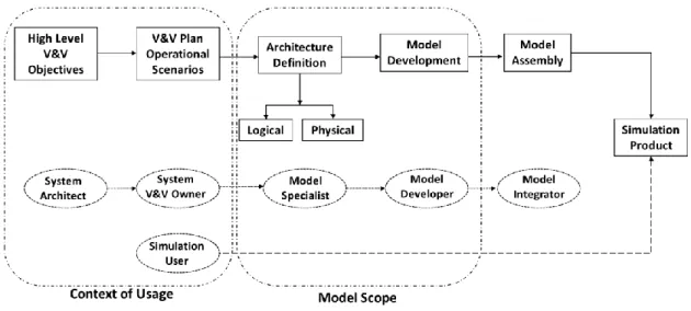
Figure 2.4: Simulation Product Development Overview ... 22
Figure 2.5: Simulation Product Development Process ... 22
Figure 3.1: EF & SUT ... 24
Figure 3.2: Experimental Frame, Model & Simulator ... 24
Figure 3.3: Real World vs Simulation World ... 25
Figure 3.4: Experimental Frame... 26
Figure 3.5: Applicability, Derivability & Abstractions - modified from ... 28
Figure 3.6: SOU & SDU - Applicability, Derivability & Abstractions... 31
Figure 3.7: EF Definition & SUT... 32
Figure 4.1: Abstraction in Modeling & Simulation ... 33
Figure 4.1: SBFIO Domain Model ... 41
Figure 4.2: Operating Modes & Transition Diagram ... 43
Figure 4.3: Mode Dependency Example ... 44
Figure 4.4: Operational Modes... 44
Figure 4.5: Modeling Abstraction Taxonomy ... 46
Figure 5.1: MR Construction Process Overview ... 49
Figure 5.2: Lattice for Voltage Assumption Class ... 52
Figure 5.3: Model Selection Results ... 54
Figure 5.4: Model Assembly ... 55
Figure 6.1: Operational View of M&S domain model ... 56
Figure 2.1: Simulation Fidelity ... 62
Figure 2.2: System & Simulation Model ... 62
Figure 2.3: System and Simulation Models ... 64
Figure 5.1: Linear Weighting ... 71
Figure 5.3: Blocking Game ... 73
Figure 5.4: Non-blocking Game ... 74
Figure 5.5: Quantitative Timed Reachability Graph ... 76
Figure 5.6: Trace Inclusion vs Refinement principles ... 78
Figure 5.7: Controller System model ... 79
Figure 5.8: Controller Simulation Models ... 79
Figure 5.9: EF & SUT Composition ... 81
Figure 6.1: Implementation ... 87
Figure 6.2: Branching in Timed Automata ... 88
Figure 6.3: Branching Implementation ... 89
Figure 6.4: Automata Games Implementation ... 89
Figure 1.1: NAIS System ... 94
Figure 1.2: Experimental Frame of NAIS Controller ... 94
Figure 1.3: NAIS TR & SD Instances ... 96
Figure 1.4: NAIS TR & SD Inferred Instances ... 96
Figure 1.5: NAIS Instances Design Space Exploration ... 97
Figure 1.6: SUT Consistency Evaluation ... 98
Figure 1.7: Architectural Comparison ... 99
Figure 1.8: NAIS Instances Design Space Exploration ... 99
Figure 1.9: Operating Modes of Valve and Solenoid ... 100
Figure 2.1: Processor Experimental Frame ... 101
Figure 2.2: Buffer System Model ... 102
Figure 2.3: Buffer Simulation Models ... 102
Figure 2.4: Trajectories Fidelity Distribution ... 103
Figure 2.5: Quantitative Reachability ... 104
Figure 2.6: Trajectories Distribution ... 104
Figure 2.7: Buffer Timed System Model ... 105
Figure 2.8: Buffer Timed Simulation Model... 105
Figure 2.9: Trace length vs Number of traces ... 106
Figure 2.10: Total number of plays distribution ... 106
Figure 2.11: Transition difference distribution ... 107
Figure 2.12: NAIS Controller Model ... 108
Figure 2.13: Fidelity distribution ... 109
Figure 2.1: Timed Automata & Reachability ... 115
Figure 2.2: Effect of Sampling ... 116
Figure 2.3: Fidelity Tolerance Example ... 117
Figure 2.4: Model Synthesis ... 118
Figure 2.5: Controller Simulation Model Synthesis ... 120
LIST OF TABLES
Table 4.1: Model Abstraction Library ... 47
Table 5.1. Battery Model Abstraction Library ... 51
Table 2.1: Quantitative Reachability Graph ... 64
Table 2.2: Dynamic System Classification I ... 65
Table 2.3: Dynamic System Classification II ... 65
Table 5.1: Equal weighted error of models ... 84
1
CHAPTER I
INTRODUCTION
Verification and Validation (V&V) activities are carried out to determine the compliance of a system, also called as System Under Test (SUT), with their specifications and fitness for their intended use respectively. Such V&V activities are usually illustrated in the classical V cycle as seen in figure 1 [Airbus] and this cycle can be broadly classified into two parts. The left branch of the cycle corresponds to design V&V where the SUT is virtual i.e. under construction and the right branch corresponds to product V&V where the SUT is physical i.e. built.
Figure 1: System V cycle, [Airbus]
In the V&V of complex engineering systems, the SUT is integrated with the other systems called environmental systems to perform some test cases and evaluate its behaviour against some user defined criteria such as performance, robustness etc. However, due to realistic limitations such as safety, cost, risk, and availability of systems this is seldom possible and these environmental systems are usually replaced by their representations i.e. models. Thus it becomes necessary to develop reasonable abstractions i.e. models of such environmental systems such that the resulting V&V activity yields same conclusions such as the ones carried out with real systems. This ability of models to replace systems by faithfully reproducing their behaviour is called simulation fidelity or simply ‘fidelity’ and it has been widely discussed in literature [Gross,1999], [Kim,2004], [Sancandi,2011], [Roza,2004].
1. MOTIVATION
Modeling and Simulation (M&S), in general, are analysis and decision means to assess performances, functionalities and operations of a system of interest [Brade,2004]. M&S is being increasingly used in product life cycle development in general and V&V activities in particular. It is used in both phases of the V cycle illustrated in figure 1, to perform V&V of the specification and the design of the SUT in the design verification phase, and of the integrated configuration and the SUT operational environment in extreme conditions, such as failure, in the product verification phase.
2
The pervasive beneficial impact of M&S is especially relevant in high technology industries such as aerospace where simulation can add value addition to the whole product development chain. At the Airbus Operations SAS of the Airbus Group, hitherto referred simply as Airbus, there is an ever-increasing tendency to use M&S during the aircraft life cycle with an ultimate objective of using Virtual Testing (VT) as a means of certification. Virtual testing can be defined as a method of testing based on the usage of simulation instead of physical test and on the usage of modeling of the physical article, instead of the physical article [CRESCENDO,2009]. A natural and logical evolution to the widespread use of M&S during the development of new aircraft, is to extend this VT as an acceptable Means Of Compliance (MOC) for certification. However, this necessitates the demonstration of the adequacy of M&S process in representing the reality. Thus the effectiveness of simulation in reproducing the reality i.e. fidelity needs to be evaluated apriori to base design choices or certification decisions of systems on simulation results.
In a classical industrial environment, a system and its representations i.e. simulation models are often developed by different stakeholders with different objectives. These SUTs, along with other systems or their models, are then tested at different V&V scenarios by a test team. System designers, who design and develop systems, are often domain experts but do not necessarily have a multi-system end user perspective. On the other hand, testers or the simulation users are not domain experts but know the context under which a SUT will be used. Then, the challenge for the model developer, who is usually in between these two stakeholders, is how to develop models of the systems called simulation model in the context of system V&V. In using M&S as a means for such system V&V, the model developer needs to find and implement abstractions of the system being simulated with respect to the simulation requirements. However, this is often a challenging task since this fidelity requirement is seldom expressed even if the context of use is well known and often it is overlooked. In addition, as the systems are getting more complex so do the M&S activities. Even with the advent of powerful computing resources, the sheer complexity of phenomena to be modeled in addition to non-technical factors such as lack of rigorous and standardized process makes M&S activities challenging. There is also neither an agreed standard to define or measure this complexity of model, nor a methodology for model developer to choose it [Brooks,1996]. This motivates an important question of how to ensure adequate level of fidelity between a system and its simulation with respect to its V&V objectives all along the product development cycle? In order to answer to this question, it is important to study the current ‘as-is’ M&S process which is briefly presented in the following section.
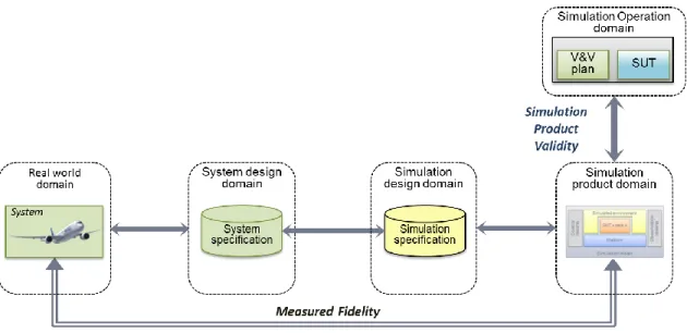
1.1 MEASURED FIDELITY APPROACH
The current practices with regard to simulation fidelity in general, and Airbus in particular, is the conventional bottom up approach process. In this process, a simulation model is developed independent of the context under which it will be used and the fidelity is only measured post priori the experiment i.e. simulation. This approach, also called as the measured fidelity approach, either results in over fidelity i.e. too many unnecessary details in the model for the scenario being tested or under fidelity i.e. too little details resulting in costly rework and thereby increasing the cost and time of the overall system V&V process. In addition, this approach necessitates the knowledge of executability of the V&V plan on the means of simulation and the confidence of the results. However, these fidelity requirements (expected capabilities, tolerances etc.) are not explicitly represented in the system V&V plan and fidelity assessment is relied upon by traditional but arduous method based on expert review, heuristics and past experience.
3
This approach is illustrated in the figure 1.1 below and it can be seen that the simulation operation domain i.e. V&V plan and SUT is not taken into account in the simulation design domain i.e. simulation specification and fidelity is only measured at the end with respect to the real system’s behaviour. Such an approach of measuring the simulation fidelity at the end is called measured fidelity [Ponnusamy,2014].
Figure 1.1: Measured Fidelity Approach
The problems of fidelity could be mitigated by explicitly taking into account the context of usage i.e. simulation operation domain into the simulation specification i.e. simulation design domain and this ‘designed fidelity’ approach is briefly discussed in the next section. A brief overview of the various challenges in the measured fidelity approach is further elaborated in section 2.2 in the context of the need for a designed fidelity approach.
1.2 DESIGNED FIDELITY APPROACH
A paradigm shift to a design fidelity approach [Ponnusamy,2014] where the modeling process is driven by the associated fidelity and validity requirements motivates the following questions. 1. How to assess the distance between a system and its simulation in general and with respect to
its V&V objectives in particular?
2. Regarding the V&V objectives, what are the fidelity requirements on the means of simulation? 3. How to develop simulation models with respect to fidelity requirements?
4. How to develop a consistent approach to evaluate fidelity of simulation models along the product development chain?
It may be seen that realization of such an approach will help improve the level of confidence in the simulation results for system V&V and help better utilization of simulation resources by selecting the best resource according to test objectives. Identification of such a consistent and continuous way to improve simulation products will help improving product life cycle quality while controlling their cost and mitigating risk. However, this designed fidelity approach, which is
4
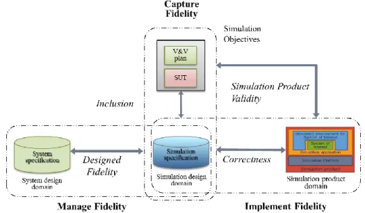
essentially the distance between the system specification and the simulation specification in figure 1.1, entails the following challenges which are broadly classified into three categories, namely,
1. Capture fidelity : How to capture the fidelity needs from the end user?
2. Manage fidelity : How to build the simulation specification according to the captured needs and the current system knowledge i.e. system specification? 3. Implement fidelity : How to ensure a consistent implementation?
The challenges are illustrated on the overall simulation product development process in the figure 1.2.
Figure 1.2: Fidelity Challenges
It may be noted that the critical challenge is on the capture and manage fidelity aspects since implement fidelity is arguably a verification i.e. correctness problem. In addition, the inclusion of simulation objectives into the simulation design domain with respect to the system being modeled i.e. system specification could also be seen. In this context, let us introduce our thesis objectives in the next section.
2. OBJECTIVES
The objective in the context of designed fidelity approach in capturing and managing fidelity is briefly given as follows,
- Define a method to capture the fidelity needs of simulations intended to be used for the V&V of avionic systems (subclass of cyber physic systems) from design phase to final product.
- Propose a method to monitor the required fidelity level through the assessment of the validity of a simulation.
5
2.1 SCOPE OF STUDY
The scope of the study has been limited to the design and product V&V of avionic systems through simulation. The study is focused on capturing fidelity requirements and implementing it through different modeling abstractions for such systems. The fidelity resulting from implementation aspects such as model of computation, hardware or software or model output perception such as visual displays has not been studied.
In addition, in the industrial context, V&V processes are only applicable to technical product requirements i.e. requirements having a direct impact on the fit, form or function of the product. The V&V of process or program requirements are covered by process assurance and project management activities respectively and are thus outside the scope of the current study.
In the following sections, the key objective of the study in capturing and managing fidelity [Ponnusamy,2015] is briefly discussed.
2.2 CAPTURING & MANAGING FIDELITY: NEED FOR A UNIFIED APPROACH
In a top down approach to M&S, owing to the fact that most of the models are rigorously verified but seldom validated, the onus must be on inclusion of validity objectives a priori in model building process as discussed in section 1.2. In this context, the first logical step would be to capture the fidelity aspects from the perspectives of simulation user or test team (simulation operation domain) and system designer (system design domain) i.e. fidelity requirements and fidelity capabilities respectively, to build a simulation specification (simulation design domain) with adequate fidelity. Fidelity requirements, according to Roza in [Roza,1999], is a formal description of the level of realism a model or simulation must display in order to achieve or to fulfill the needs and objectives of the user of the model or simulation. Similarly, the design decisions employed by the system designer to build the system specifications have to be considered which gives a measure of available fidelity i.e. capability. Once the fidelity is captured in terms of its requirements, the next step is to manage or assess this requirements vis à vis the capabilities via abstractions and the inclusion relations introduced in section 3.4 of chapter II between them. In this top down approach, simulation developer has to take design decisions as to what are the possible abstractions of the system specification with respect to the fidelity requirement? However, as remarked in [Brooks,1996], there exists no agreed standard or a guideline to choose this level of model complexity owing to the innate nature of problem in quantifying this complexity i.e. abstraction level vis à vis requirements.
This capture of requirements and development of models for cyber physical systems resulting from the confluence of control, communication and computing paradigms [Clark,2013] is an active research area as such systems are becoming ubiquitous especially in transportation domain such as in avionic systems. In V&V of such systems, there is a problem of heterogeneity due to different modeling formalisms used by different stakeholders leading to interoperability issues particularly during the model integration phase. In addition, the complexity of the process is higher, especially in an industrial context of simulation product development the modeling phase involves requirement collection, conceptual modeling, model formulation, model construction, assembly and deployment on the platform. Then the simulation phase involves experimentation according to V&V plan, data collection, analysis and conclusion. All such activities involve multiple levels of abstraction, stakeholders, formalisms and tools. In particular, the system specification (system
6
design domain) and/or simulation requirements (simulation operation domain) are not only at different levels of abstraction (design vs operational) but may also be expressed formally (e.g.: models), informally (e.g.: text) or a combination of both. Such complexities give raise to two key challenges for the model developer, namely, how to define requirements, called as Model Requirements (MR), from informal system specification and scenario description? and how to rigourously specify model behaviour based on this MR? A single approach to tackle this complexity is neither feasible nor practical and a rigorous multi modal system engineering approach is needed.
In this model based approach, effectiveness largely depends on the degree to which design concerns captured in the different abstraction layers by different stakeholders are orthogonal, i.e. how much the design decisions in the different layers are independent [Clark,2013]. Such a multi modal or multi view modeling approach has been widely discussed in terms of reasoning, functional modeling, qualitative modeling and visuo-spatial reasoning etc. [Fishwick,1993]. However, such studies are discussed mostly in modeling perspective and the problem of fidelity is not explicitly addressed. The unified approach presented in this thesis attempts to leverage the flexibility of semi-formal approaches and rigor of formal approaches to address the problems of complexity in the designed fidelity approach [Ponnusamy,2014]. In particular, the semi-formal approach concerns the system design and simulation requirements expressed in an informal context such as natural language texts whereas the formal approach concerns the same knowledge expressed through behavioural models. In reality, a model developer has to deal with both the formal and informal system design and simulation requirements to build a simulation model and it is important to provide the practicing model developer a perspective and mechanism to build these models with adequate fidelity. The two perspectives are necessarily based on the level of abstraction in the M&S process, i.e. capture and manage fidelity, both informally (qualitatively) and formally (quantitatively). These two perspectives are briefly presented in the following sections.
2.2.1 Semi-formal Perspective
The semi-formal perspective addresses the first or top level challenge of how to define MR from informal system specification and scenario description? It essentially concerns only the structure of the dynamics which is usually expressed informally in natural language texts, and not their quantifiable effect. In other words, semi-formal perspective deals with the different levels of abstraction resulting in a structure of the system dynamics or dynamics itself albeit at higher abstraction level. This top level perspective to M&S is equally important in understanding and explaining complex systems, as the current languages of systems engineering are usually informal (text and pictures) but seldom formal or even semi-formal (rigorous domain-specific languages).
In system engineering, especially in an industrial context, it is known that each component systems are developed by different multidisciplinary teams often working transversely and transnationally. These component systems usually interact with each other to perform, for example, a Multi System Function (MSF) in an integrated system. In the M&S of such complex systems, one of the key challenges is the lack of common understanding between the stakeholders, semantic inconsistency, and interoperability [Benjamin,2009]. For example, ‘calculate and display aircraft position’ function is performed by Global Positioning System (GPS) and inertial data system which are communicated to Cockpit Display System (CDS) to inform the pilot. However, from this
7
informal textual description, identification of the functional contribution of each such system to MSF, its composition, interaction etc. could be difficult and this equally true for identification of other perspectives on the system.
The designed fidelity approach, introduced in section 1.2, necessitates collection of such knowledge about the system to be modeled and scenarios under which it will be operated respectively. This is then used to build the Model Requirements (MR) incorporating only the essential elements needed for the test which will then be used to develop a Model Specification (MS). However, owing to the complexity of different domains of knowledge involved which are often implicit and incomplete, it is a tedious task to define this MR manually. This is compounded due to the lack of a consistent derivation of low level V&V requirements from high level V&V objectives. The requirements traceability between these two domains is seldom one-to-one and the inclusions of low level requirements in the high level requirements are traditionally managed by heuristics, domain expertise, margins and experience. In addition to this lack of standardization and incompleteness of the domain knowledge, there exists no standard method to exploit or reuse its contents. This is usually done manually through stakeholder expertise and document review which is not only cumbersome but also time consuming and often redundant. These challenges in simulation model development necessitate a Model Based System Engineering (MBSE) approach which enables a common understanding by making domain assumptions explicit and separate domain knowledge from the operational knowledge [Noy,2001]. Such a semi-formal approach must be flexible enough to accommodate multiple viewpoints on the system which are often interrelated and at the same time be rigorous enough to identify incompleteness or inconsistencies between them. In addition, it must be amenable for exploitation through some query mechanisms, archival and must be scalable with respect to the domain knowledge and user implementation complexity.
2.2.2 Formal Perspective
The semi-formal perspective has limitations in capturing the dynamics of (reactive) systems and a fidelity approach will only be complete if the fidelity requirements usually expressed as a distance notion, e.g.: tolerances over desired behaviour, are adequately captured in modeling. The formal perspective, thus addresses second or low level question of how to rigourously specify a model’s behaviour with respect to the system it represents? In general, in a classical or even a MBSE modeling approach, as remarked by Cowder et al [Cowder,2003], most of the design activities, around 90% in some cases, are based on the variants of the existing designs. This is true in V&V activities too where existing models are often reused to build a more complex but variant models of environmental systems of the SUT. In certain cases, models of such systems called design models might be available but could not be used due to practical constraints on resources, platform limitations and compositional complexity. However, as remarked in section 1.1, such models are developed independent of their end-use fidelity requirements with no formally i.e. mathematically rigorous, guaranteed bounds on their behaviours especially after composition, resulting in behavioural fidelity issues only to be discovered at the later stages. In addition, with current ad-hoc methods of model development, a model is developed as ‘fidle’ as possible i.e. as detailed as possible hoping it would cater to as many test scenarios as possible during the V&V activity. This is clearly a sub-optimal process especially in the context of changing specifications and scenarios. On the other hand, questions on a model’s fidelity for a scenario different from the one for which
8
the model is originally developed for are neither answered formally nor apriori to the actual simulation.
In order to mitigate such problems, a component based approach is needed which quantifies fidelity of simulation model component’s behaviour with respect to all the system’s behaviour, both globally and with respect to the V&V objectives. In addition, in such an approach a composition with other models should not result in a compositional complexity i.e. assuming fidelity distance of components M1 and M2 be ε1 and ε2 respectively with respect to their system specifications, when they are composed to form a third component, M1⨁ M2= M3, then the fidelity of this resulting component, ε3 must be bounded, ε3≤ ε1+ ε2 [Tripakis,2016]. This behavioural fidelity perspective implies that there must be formal i.e. mathematically rigorous way to quantify the simulation model with respect to the system being modeled.
Formal Methods are descriptive notations and analytical methods used to construct, develop and reason about mathematical models of system behaviour. A formal method is a formal analysis carried out on a formal model, a model defined using a formal notation [Tiwari,2003]. A formal notation is a notation having a precise, unambiguous, mathematically defined syntax and semantics. Formal method uses mathematical reasoning to guarantee that properties are always satisfied by a formal model. There are various techniques available such as deductive techniques (theorem proving) [Duffy,1991], model checking [Clarke,2000], and abstract interpretation [Cousot,1992]. Since formal methods possess sound mathematical basis, a false assertion is not possible. In general, a formal verification approach intends to prove that the system satisfies (or not) a given property and this verification problem could be formalized as a reachability analysis problem in a finite labeled transition system which includes the problems of proving safety, liveness etc. [Vardi,2009]. This is a method to show that the system defined by a computational model such as automata, satisfies the desired properties, i.e. all the behaviours generated by the system are those accepted by the specification defined by a specification language such as temporal logic [Pnueli,1977]. Though fidelity per se does not intend to (dis)prove a property but only is a measure of closeness to system being modeled, the principles of formal verification such as reachability analysis could be used to rigorously quantify the fidelity [Ponnusamy,2015]. In other words, classical formal verification techniques usually done to demonstrate morphism [Ziegler,2000] between specification and implementation is extended to show the morphism between the system specification and its abstraction (simulation model) for the purpose of quantifying the degree of similarity between them i.e. fidelity distance.
The formal approach, in general, helps in standardizing and automatizing V&V activities and has been increasingly used in the field of software and hardware design [Clarke,2000]. Though they are widely used in software verification and to some extent in system design [Alur,2015], application of such approach in simulation design domain especially in the context of fidelity has not been done adequately. The benefit of using classical formal method, especially in the early design verification phase has been widely discussed in literature [Ben,2003],[Clarke,2000],[OSKI]. In the case of V&V by simulation, the exponential growth of verification effort with design size could be greatly alleviated by using formal tools along classical simulation especially before model composition and integration in the simulation platform.
It is also to be noted that when a formal model is created from an informal knowledge usually expressed at higher abstraction levels such as in a semi-formal perspective discussed in section 2.2.1 to perform a formal analysis, it needs to be ensured that whatever is proved about the formal model also applies to what is modeled. Then review or analysis should be used to demonstrate that
9
the formal statement is a conservative representation of the informal requirement. Thus the two perspectives could be seen to be complimentary in capturing and assessing fidelity at different layers of abstraction to ensure overall fidelity of the resulting simulation product.
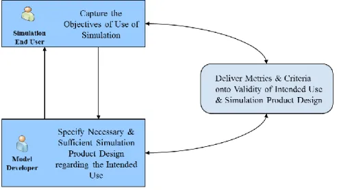
2.3 KEY BENEFITS
The intended key benefits of the unified approach proposed in this thesis based on the formal and semi-formal perspective to the M&S stakeholders are briefly presented below.
Model Developer - Help find the set of allowable abstractions for model to be developed with respect to V&V objectives.
- Provides synthetic & accurate descriptions of simulation end user's intention in order to implement only relevant details.
- Use templates and pattern to describe the designed fidelity and apply abstraction.
Simulation User - Help find the model developed by design abstraction that fit their needs in terms of V&V objectives.
- Use templates to describe their intention. - Increase confidence in the simulation results.
Figure 2.1: Proposed Approach
System designer - Help formalize the system design in a standardized, interchangeable template.
The proposed approach to build the designed fidelity progressively all along the life of simulation products is illustrated in figure 2.1.
10
3. THESIS CONTRIBUTIONS
The overall contribution of the thesis towards an unified approach to the fidelity problem is essentially threefold, namely,
1. Formalization of fidelity problem as an inclusion problem, detailed further in section 3.4 of chapter II, in the established M&S notions of the experimental frame [Zeigler,2000].
2. A domain model approach in the semi-formal context to assess and define the simulation fidelity qualitatively.
3. A behavioural metric approach in the formal context to assess and define the simulation fidelity quantitatively.
In addition, a process oriented view for each of these approaches to simulation fidelity has been discussed in an industrial context. The major contribution of the thesis is the proposition of a domain model approach i.e. semi-formal and behavioural metric approach i.e. formal to this inclusion problem which is briefly presented in the following sections. The associated publications could be seen in the Publications section of this thesis.
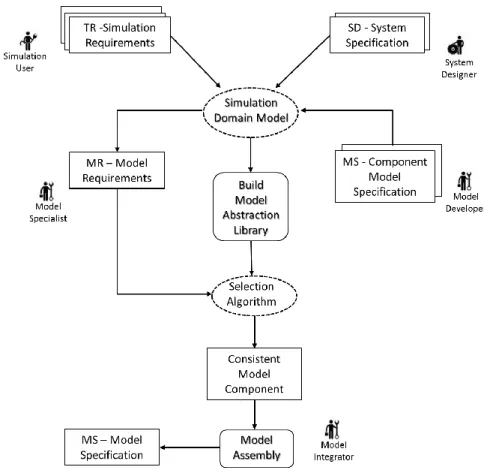
3.1 DOMAIN MODEL APPROACH
The designed fidelity approach, in the semi-formal context, necessitates the collection of knowledge about the system to be modeled and scenarios under which it will be operated which normally involves interaction between system designers, testers and model developers. However, owing to the complexity of different domains of knowledge involved which are usually at different levels of abstraction, it is a tedious task to define the essential elements to be modeled for a given test. In order to alleviate this complexity and standardize the knowledge which could then be exploited, we propose a domain model approach based on ontologies in chapter III. This domain model is essentially a ‘knowledge template’ i.e. an ontology which captures the system design and test scenario knowledge into pre-defined, standardized concepts and relationships [Ponnusamy,2016],[Thebault,2015]. This approach has been chosen due to the flexibility in expressing different domain knowledge in a succinct and standard form through standardized language of OWL [OWL], in tools such as Protégé [Protégé] with query [SPARQL] and reasoning [Grosof,2003] capabilities. Ontologies, in general, have been widely used to tackle complexity in the field of artificial intelligence, semantic web, bioinformatics, information science etc. by standardizing and organizing domain knowledge. Though ontologies in the M&S were addressed in literature, albeit at high level, for example in [Fishwick,2004], [Oren,2014], [Kezadri,2010], they were not explored sufficiently in a MBSE context for simulation model development. In addition, a holistic application of ontology, especially to the problem of simulation fidelity, by leveraging the flexibility, scalability, reasoning and query capabilities of ontologies has not been studied adequately to the best of our knowledge.
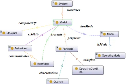
In the teleological modeling of complex engineering systems, different ontologies such as Functional representation [Chandrasekaran,1993], Structure-Behaviour-Function [Gero,2004] have been discussed in literature. The classical Structure, Behaviour, Function (SBF) framework is one of the widely used and mature ontology to specify the system’s function and the causal processes that result in them at multiple layers of abstraction [Goel,2009]. In this thesis, we extend this classical SBF ontology to the domain of simulation in section 4 of chapter III and introduce
11
additional notions of interface (I) and Operation (O) to describe interconnected system with different modes of operation [Ponnusamy,2016]. In the Operation ontology, we have proposed the concept of Operating Mode, based on the classical formalisms such as modechart [Jahanian,1994] and mode automata [Maraninchi,1998], but is believed to be more amenable to describe a system’s modes of operation at higher levels of abstraction. In addition, our domain model comprises of different generic concepts (e.g.: Datatype), industry or domain specific concepts (e.g.: Criticality Level, Airbus internal standards) and among others, a test ontology to capture the test scenario knowledge. The domain model has been constructed based on the academic and industrial state of art such as SBF framework, common MBSE approaches such as SysML [SysML,2006] CAPELLA [Roques,2016], Airbus internal M&S processes and standards, interviews and discussion with the V&V stakeholders which is further elaborated in section 1 of annex.
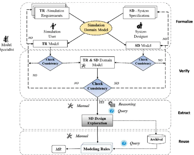
In an industrial context, it is important to illustrate how such a domain model approach improves the existing processes with minimal disruptions. A process to utilize this domain model to define requirements on a simulation model is proposed in section 5 of chapter III. In particular, a three step process of capturing the system and test scenario knowledge through the domain model, using reasoning approach to check consistency and using queries to extract information is proposed in this thesis. The domain model is implemented in the Protégé tool [Protégé] and different query mechanisms were defined to verify and extract information at mulitple layers of abstraction to build a MR. The application of this approach is demonstrated with a real industrial case study of the aircraft Nacelle Anti-Ice System (NAIS) in section 1 of chapter V . The results from the case study discussed in section 1.2 and 1.3 of chapter V were highly promising especially in the context of knowledge standardization, reuse, archival and query capabilites. The challenges in practical implementation and outlook were discussed in section 6,7 of chapter III and section 1 of chapter VI.
In addition, we have also shown that the output of this MR construction approach could be used as an input to the MS construction process by automatically selecting a consistent model from a model library based on the recursive procedure proposed by Levy et al [Levy,1997]. In section 6
of chapter III we have given an operational perspective of this entire MR and MS construction process based on the existing industrial processes.
3.2 BEHAVIOURAL METRIC APPROACH
The designed fidelity approach, in the formal context, necessitates a component based design approach for developing a simpler representation of the constituent systems wherein each component must be adequately representative enough to perform V&V on the SUT. The key question in this approach is how to measure this fidelity i.e. how closely (or not) does the model simulate i.e. ‘mimic’ the system behavior [Ponnusamy,2016]? However, quantifying fidelity, especially in a formal manner, is often a challenging task since it requires real system behaviour to compare against the model behaviour. This post-priori measurement of fidelity happens often at detrimental cost due to over or under specification of models as mentioned in section 1.1. Instead, this fidelity needs to be measured a priori both globally and locally i.e. with respect to V&V objectives before integration with other models, SUT and deploying on the simulation platform as discussed in section 2.2.2. In order to formally quantify this fidelity between a component system model and a simulation model, we propose a formal approach in chapter IV which assigns a metric
12
to quantify this degree of similarity with respect to all possible or a subset of behaviours of the system based on the notions of game theory and formal verification principles.
Our approach is based on the quantitative extensions of classical simulation relations [Milner,1989] proposed in the context of discrete systems [Henzinger,2013],[Chatterjee,2015] and continuous systems in [Girard,2007], [Pappas,2003]. In the former, a distance notion based on two player game for automata [Cerny,2010] and interface automata [Cerny,2014] gives a transition-wise or path-transition-wise distance in the context of implementation, coverage and robustness. In the later, an approximate bisimulation relation essentially giving a global error bound i.e. maximum degree of dissimilarity between two models at a given time instant is proposed. This is then formally verified by geometric over approximation of the reachability set through zonotopes [Girard,2005], ellipsoids etc. However, in the field of (discrete) simulation, such global bound is over-conservative since according to a scenario a model might still be valid locally despite its global error [Ponnusamy,2016]. Similarly, the distance notion proposed for untimed discrete systems in [Cerny,2010], [Cerny,2014] and timed discrete system [Chatterjee,2015] concerns only fidelity distance evaluated transition-wise for a particular path. This may not be adequate since not all such possible paths are explored. In other words, not all scenarios i.e. input combinations are considered. This necessitates finding such distance bounds on all possible paths evaluated over a positive real valued distance function. This generation of fidelity distance between every possible path of the system and simulation model for every possible input is also called as a quantitative reachability graph. An analysis of this graph will yield further insight into the adequacy of abstraction globally or with respect to V&V objectives. However, to the best of our knowledge, such a mechanism to quantify this distance for all possible inputs i.e. a superset of test scenarios between any two given models has neither been proposed nor been implemented especially in a fidelity context.
The behavioural fidelity metric approach is proposed for discrete systems in sections 5 of chapter IV whereas some theoretical results for linear continuous systems [Ponnusamy,2016] can be found in the annex. In the discrete systems case, our approach concerns both the open i.e. reactive to its environment and closed i.e. non-reactive to its environment modeled by automata and interfaces respectively [Alfaro,2003]. This is important since behavioural fidelity problem arise from a simulation model’s internal structure (modeled as automata) as well as its environmental assumptions/guarantees (modeled as interfaces) and it is important to study the quantitative reachability approach for both such complementary paradigms. In particular, in the case of closed timed systems modeled as timed automata, we have proposed a turn based semantics specifically in the context of fidelity for the quantitative reachability graph generation in section 5.2.1 of chapter IV.
We have modeled this game based formal fidelity quantification for all such different class of systems in (Timed) Petrinet formalism. (Timed) Petrinets, is an extension of classical Petrinet formalism [Peterson,1981] with firing time for the events and an extension of it with data handling called Time Transition Systems [Berthomieu,2014] is used in our approach. The token based formalism of the Petrinets is amenable to model such turn based games which is explained in detail in chapter IV. In addition, the availability of state of the art and in house developed Petrinet analyzer tool called TINA [Berthomieu,2004] with its graphical editor and reachability generation capabilities renders it an attractive choice for our implementation which is discussed further in
section 6 of chapter IV. Since the quantitative reachability graph generated by TINA is in textual form, we have also developed a parser to rebuild all the paths which will then be used to perform some analytics such as finding a path with least or maximum distance, distribution of fidelity
13
distance etc. In addition, our Petrinet implementation allows incorporating different fidelity distance metrics such as transition weighted error, absolute error, non-weighted error etc. according to the user need. The demonstration of our approach and implementation were presented in section 2 of chapter V for an (un)timed model of a buffer system, untimed interface model of NAIS with different types of abstractions. Despite the challenges of scalability of our explicit enumeration approach, initial results indicate even for a limited reachability exploration (for example <106 paths), our method gives valuable insights on the distribution of fidelity which could be then be used for deployment, model repair or simply archival.
In summary, despite the seemingly orthogonal solutions proposed in this thesis, namely domain model approach and behavioural fidelity metric approach, they both serve their purpose in improving fidelity albeit at different levels of abstraction. The domain model approach standardizes and exploits the often informal domain knowledge to build a semi-formal MR with adequate levels of fidelity. This would then serve as a baseline upon which the model developer chooses the model existing variants whose level of fitness for a given purpose i.e. to validate the SUT using simulation is given by our formal approach. Another key benefit of this unified approach is these two methods can either be used independent of each other or complementary to each other depending on the prevailing fidelity issues and user’s need as seen from the thesis roadmap section. The plan of the thesis is given in the next section.
4. THESIS PLAN
The key challenge of the designed fidelity approach is to develop a mechanism to collect the fidelity requirements and then to evaluate the model against these requirements. This thesis is broadly focused on identifying the challenges in developing such a mechanism and solutions for mitigating them at multiple levels of abstractions followed by its demonstration on application case studies. In the unified fidelity framework context, the semi-formal and formal approaches are detailed in chapter III and chapter IV respectively with their application case studies presented together in chapter V. The intended key benefits of the approach listed above are evaluated in each such chapter and relevant conclusions are drawn which are further discussed in chapter VI. In this context, the chapters of the thesis are organized as follows,
Chapter II : The second chapter addresses the background and problem formulation of our designed fidelity approach through the established theory of modeling and simulation framework of experimental frame formalism and inclusion relations between them.
Chapter III : This chapter presents the semi-formal approach based on the principles of ontologies in building a domain model to capture, formalize and evaluate the knowledge of simulation fidelity requirements with respect to the system specification to build high level simulation specification with sufficient fidelity.
Chapter IV : The formal approach based on the principles of formal verification and game theory to quantify fidelity of simulation models with respect to their system specifications for different class of systems is presented in this chapter.
14
Chapter V : The results of applying the semi-formal and formal approaches to the case studies were detailed in this chapter.
Chapter VI : The last chapter focuses on the overall and specific outlook on our unified approach, challenges ahead, axes of future work and conclusion.
In addition, associated information not detailed in the aforesaid chapters such as pseudo code, methodology implementation etc. could be found in the annex. The bibliography section contains list of references used in the study.
15
CHAPTER II
EXPERIMENTAL FRAME & INCLUSIONS
In this chapter, the designed fidelity approach is discussed in the context of a unified perspective in building a simulation Experimental Frame (EF) through inclusion relations. In order to better understand the problem formulation especially in the context of chapter I, a brief overview of the context and background is presented in the following sections.
1. BACKGROUND
In this section, some generic definitions and background information on system V&V, M&S and the associated fidelity notions from the industry and academia are briefly discussed.
1.1 SYSTEMS VERIFICATION & VALIDATION
According to Brian Gaines, a system is what is distinguished as a system which essentially means that to distinguish some entity as being system is a necessary and sufficient condition for its being as a system [Gaines,1979]. A system is usually characterised by what belongs to it and what it doesn’t belongs to it. The systems theory focuses on arrangement and interdependent relationships between the components of a complex system and distinguishes between a system’s behaviour and structure. Such a definition is echoed by the Airbus definition of system as abstract entities, introduced by a standardization authority (ATA 100) defined as a set of equipment [FAA,2002]. In addition, according to INCOSE, System engineering, a multidisciplinary field, is defined as an iterative process of top down synthesis, development, and operation of a real world system that satisfies, in a near optimal manner, the full range of requirements for the system [INCOSE,2011]. More specifically, IEEE standard 1362 [IEEE,2007] defines a system as a collection of interacting components organized to accomplish a specific function or set of functions within a specific environment.
A system can be either closed or open depending on its reactivity to its environment. A key property of a reactive system which interacts with its environment is it can be controlled through variables called input that are generated from the environment to influence the system and observed through outputs which are variables generated by the system and influence its environment. Such an interpretation leads to a concise definition of system being a source of data. The process of extracting data from such a source i.e. system by exerting with input is called an experiment. An experiment could either be real e.g. flight tests or virtual e.g. simulation to perform verification or validation activity on the system under test.
In this context, Validity of a system is measured through validation activities (to answer ‘did I develop the right product?’) and Correctness through verification activities (to answer ‘did I develop the product right?’) [Brade,2004]. In addition, validity has another perspective with respect to product requirement, called requirement validity (to answer did I ask the right questions?). Hence product validity is given by its requirement validity and correctness. These V&V activities
16
are carried out according to some V&V plan formulated usually by the system designers or architects. Such an activity through an experiment is usually comprised of different sub-experiments called test scenarios, usually supplied by the test team, which essentially describes what is expected of an experiment and how it is done on the system built by the system designers.
1.2 MODELING & SIMULATION
In general, the process of describing the system as a model is called modeling and the process of experimenting the model is called simulation. A model is essentially an abstract representation containing the essential structure of some object or event in the real world. More precisely, according to IEEE 610.12-1990 standard [IEEE,1990], a model is formally defined as an approximation, representation, or idealization of selected aspects of the structure, behaviour, operation, or other characteristics of a real-world process, concept, or system. Thus modeling is the process of generating abstract, conceptual, graphical or mathematical models of a real system whereas simulation is the imitation of the operation of real-world process or system over time [Cellier,1991]. A simulation generates an artificial history of the system behaviour and upon observation of that observation history, design decisions or analysis could be made for the real system. Hence, the simulation could be used as an analysis tool for predicting the effect of changes or as a design tool to predicate the performance of new system [Balci,1997].
Marvin Minsky defines a Model for a system as anything to which experiment can be applied in order to answer questions about the system [Cellier,1991]. Thus a model is always related to the tuple of system, S and experiment, E [Zeigler,2000]. Hence notations like validity, fidelity etc. of a model must be addressed in association with the system it represents and experiment which it intended to address.
1.3 FIDELITY
A brief survey on the notion of fidelity and its manifestations with respect to modeling and simulation are given in the following sections.
1.3.1 Definition
Fidelity is often used in different contexts both in scientific and non-scientific fields alike, however, it would in general, as a classical definition of Oxford dictionary imply, the degree of exactness with which something is copied or reproduced. A myriad of interpretations of fidelity, especially in the M&S community leads to inconsistency in the Verification, Validation & Accreditation (VV&A) activities and this necessitates a precise notion of this generic term. In the present thesis fidelity is defined as a notion of ‘distance’ to reality and by assigning a metric this distance could be measured quantitatively. Fidelity, henceforth, is defined as the distance from the
simulation of a system to the simulated system. This definition is akin to widely accepted
definitions such as the US Department of Defence (DoD) stating fidelity as the accuracy of the representation when compared to the real world. Simulation Interoperability Standards Organization (SISO) fidelity Implementation Study Group (ISG) formally defines fidelity in [SISO,2013] as
17
The degree to which a model or simulation reproduces the state and behaviour of a real world object or the perception of a real world object, feature, condition, or chosen standard in a measurable or perceivable manner.
In stating that fidelity should generally be described with respect to the measures, standards or perceptions used in assessing or stating it, SISO further defines it by,
The methods, metrics, and descriptions of models or simulations used to compare those models or simulations to their real world referents or to other simulations in such terms as accuracy, scope, resolution, level of detail, level of abstraction and repeatability.
Fidelity can thus characterize the representations of a model, a simulation, the data used by a simulation (e.g., input, characteristic or parametric). Each of these fidelity types has different implications for the applications that employ these representations. In addition, SISO emphasises the referent i.e. simulation fidelity requirements must be carefully defined in terms of how much is to be simulated (i.e., entities and characteristics) and what interactions are involved (i.e., relationships between entities in the referent). SISO identifies a key obstacle in acceptability of M&S methods as a tool to make design decision for real world problems is defining a fidelity metric which measures the simulation behaviour. In defining fidelity as a measure of distance to reality, abstractions in modeling could be seen as the cause of this distance. An abstraction level in complex engineering simulations such as for aircraft is a crucial factor in influencing resources deployed to use simulation as a means in system design and development. An incorrect or inconsistent choice of abstraction level of model will result in prohibitory complexity in overall simulation process and thereby its validity and fidelity. In the next section, the notions of fidelity and validity are discussed with respect to this modeling abstractions.
1.3.2 Fidelity, Validity & Abstraction
A unified approach to fidelity was done by Roza in [Roza,2004] where a mathematical formulation of fidelity and the fundamental concepts underlying its characterization and measurement were established, parts of which are comprised in SISO ISG report [SISO,2013]. The study establishes that Fidelity quantification and qualification doesn’t equate to validity of simulation (Theorem 6, [Roza,2004]). It follows from the preceding result that fidelity is an intrinsic or absolute property of any model or simulation characterizing its degree of realism (Theorem 3, [Roza,2004]) and an absolute metric of fidelity could never be established owing to the inherent levels of uncertainty (Theorem 1&2, [Roza,2004]). In addition, Roza (Theorem 7, [Roza,2004]) and Zeigler [Zeigler,2000] states that model fidelity and simulation fidelity do not equate. Thus a formal metric relating the fidelity and validity of simulation becomes imperative and, this question of relation between the simulation behaviour and its objective could be addressed vis à vis the factors affecting the fidelity of simulation outcome with respect to the validity, namely, abstractions used in modeling. In framing a metric between the abstraction used in model development and its associated objective of use, a bridge could be made between the fidelity (degree of realism of model) and validity (degree of correspondence to objective of use). Brade et al [Brade,2004] emphasis this relation of fidelity with validity by defining fidelity as a measure to show that the model and its behaviour are a suitable representation of the real system and of its behaviour with respect to an objective of use of the M&S product. Since fidelity is one of the vital drivers in terms of development and deployment cost in simulation, an early quantification of fidelity helps in better simulation product development for system validity assessment.
18
1.3.3 Fidelity Classification & Metric
In the study by Roza [Roza,2004], fidelity has been classified into eight classes namely detail, resolution, accuracy, interaction, temporality, causality, precision and sensitivity. Fidelity was also classified as esoteric fidelity i.e. an ideal measure and practical fidelity with a proposition on a domain independent fidelity criteria evaluation. In evaluating this fidelity, quantitatively or qualitatively, the evaluation could be carried out within the ambit of these eight characterisations. In specifying the real world reference knowledge specification template, the real world was specified as a system of interacting subsystems in a hierarchical object oriented fashion.
Another classification of simulation fidelity from the end user perspective in terms of perceptive fidelity and behavioural fidelity was put forth by Robert Hays [Hays,1980] based on definitions of Kinkade, Wheaton, Farina et al. [Kinkade,1972]. The perceptive fidelity classification deals with end user experience of the simulator in the following terms:
Equipment fidelity (physical configuration) – e.g.: a flight simulator to evaluate flight control laws has gauges, dials, control sticks etc.
Environmental fidelity (duplication of environmental context) – e.g.: motion cues, dynamic representation of environment such as sky, ground etc.
Psychological fidelity – e.g.: level of psychological perception of the end user as realistic though it may turn out to be otherwise.
The behavioural fidelity also referred by the authors as task fidelity is akin to generic notion of simulation fidelity which is described in this thesis as a degree of representation of real world by the simulation. However, these definitions fell short of relating between the representation of real world and simulation objectives and its context of usage since a model is always developed with an objective behind. It may also be noted that these definitions are more to do with training simulators for mature systems rather than with simulators used in system design and development especially in the design verification phase of figure 1 of chapter I which this thesis is focussed on.
In addition to such classification, a metric on fidelity is useful to gauge the rigour of simulation models. The metric could either be qualitative (e.g.: low/medium/high) or quantitative [SISO,2013], though quantitative metrics are often overlooked, they could well be attributed to a related qualitative metric and vice versa. In practice, both qualitative and quantitative metrics are useful, since the former is amenable for subjective evaluation by human domain experts and the later for objective evaluation of some specific characteristics. However, even before ascribing a metric, qualitative or quantitative, we need a mechanism to improve the fidelity of models by choosing right level of abstraction which then can be compared against a given metric. In this thesis, our semi-formal approach, presented in chapter III, is used to qualitatively (yes/no) evaluate fidelity by answering what are all the scenarios that can(not) be modelled based on system specifications? Similarly, our formal approach, presented in chapter IV, is used to quantitatively (a real valued function) evaluate what is the component model’s fidelity with respect to the system specification?
It may be noted that our designed fidelity approach is not intended to propose a metric per se, but to propose a mechanism to improve the fidelity of the overall process which can then be assessed with any given metric. Thus it is amenable for further extension or modification of the fidelity metric and in doing so the inclusion principles of neither the domain model approach nor the formal approach is expected to change. For example, current qualitative evaluation of domain
![Figure 3.5: Applicability, Derivability & Abstractions - modified from [ Zeigler,2000 ]](https://thumb-eu.123doks.com/thumbv2/123doknet/2090282.7385/48.918.298.638.593.936/figure-applicability-derivability-amp-abstractions-modified-zeigler.webp)