THESIS PRESENTED TO
ECOLE DE TECHNOLOGY SUPERIEURE
IN PARTIAL FULFILLMENT OF THE REQUIREMENTS FOR A MASTER’S DEGREE IN MECHANICAL ENGINEERING
M.Eng.
BY
Jonathan VILLIARD
TEST RIG AND EXPERIMENTATION OF PACKING SEALS USED IN LARGE DIAMETER DEFORMED ROTATING DRUMS
MONTREAL, DECEMBER 22 2010 © Copyright 2010 reserved by Jonathan Villiard
BOARD O F EXAM INERS (THESIS M. ENG.) THIS THESIS HAS BEEN EVALUATED BY THE FOLLOWING BOARD OF EXAMINERS:
Mr. Hakim A. Bouzid, Thesis Supervisor
Departement de genie mecanique a l’Ecole de technologie superieure
Mr. Jean Arteau, President of the Board of Examiners
Departement de genie mecanique a l’Ecole de technologie superieure
Mr. Patrick Terriault, Member of the Board of Examiners
Departement de genie mecanique a l’Ecole de technologie superieure
Mr. Paul Goudreault, Vice-President Process & Technology GEA Barr-Rosin Inc.
THIS THESIS HAS BEEN PRESENTED AND DEFENDED BEFORE A BOARD OF EXAMINERS AND PUBLIC
DECEMBER 15,2010
I would like to thank GEA Barr-Rosin for proposing and financing this interesting project and more specifically Paul Goudreault for the thrust and support through the realisation of this project. His guidance and assistance were greatly beneficial to the success of this work.
Equally, I would like to thank my director, Hakim A. Bouzid, for sharing his knowledge and experience without restriction. M. Bouzid has been a driving force and a great mentor from the beginning of this long quest. I am truly grateful for being one of his graduated students.
I would like to thank my parents, Pierre and Mireille Villiard, for their invaluable support during my studies. Thanks for giving me the motivation and for believing in me.
I would like to thank my girlfriend, Claudine Hug, for her patience and understanding with those extensive working hours. Her love and presence made it seem easier.
I would like to thank, Etienne Lacroix, for his friendship and his precious advises. Thanks to my colleague, Mark Roald, for taking the time to review my thesis, his inputs were much appreciated.
I would like to thank my colleague, Barrie Mathews, for teaching me everything he could on rotary processor, for transmitting his passion for engineering and for being such an incredible mentor.
Finally, I would like to thank the team of technicians, engineers and teachers at the Ecole de Technologie Superieure for their support in answering my questions and for teaching me everything I needed to achieve this project.
BANC D’ESSAIS ET EXPERIM ENTATION DE JO IN TS TRESSES SUR UN TAMBOUR ROTATIF DEFORM E DE GRAND DIAM ETRE
Jonathan VILLIARD RESUM E
Les processeurs de grandes dimensions tels que les sechoirs rotatifs et les calcinateurs rotatifs sont difficiles a sceller; ils ont de grands diametres, leurs methodes de fabrications sont imprecises et ils subissent de severes conditions d’operation. Ces facteurs produisent plusieurs types d’imperfection a la surface de scellement. Ce travail porte sur la possibility de sceller ces processeurs rotatifs de grand diametre jusqu’a une pression de 1 atmosphere (14.7 psig).
Premierement, une etude theorique combinee a revaluation de donnees acquises en chantier est conduite afin de determiner 1’amplitude de chacun des defauts presents a la surface de scellement.
A
partir de ces resultats, les joints d’etancheite typiquement utilises dans l’industrie sont evalues et compares. Les joints en forme de garnitures de compression tressees demontrent de grandes possibilites puisqu’ils sont deja utilises avec succes pour sceller des applications de grand diametre avec une pression positive. Ces garnitures sont generalement utilisees dans un arrangement de type presse-etoupe, cette arrangement est done etudie afin d’en comprendre ses particularites.Les donnees collectees et calculees dans les etapes precedentes sont rassemblees et servent de parametres de conception pour le nouveau joint d’etancheite. Le nouvel arrangement propose a comme principales caracteristiques la compression radiale et l’utilisation d’un boitier flexible adaptatif. Basees sur les relations mathematiques disponibles pour les presse- etoupes, les equations sont reevaluees et reformulees pour satisfaire la nouvelle disposition radiale. Un banc d’essais est aussi congu et fabrique afin de mesurer les performances du nouveau systeme de joint et pour comprendre son comportement. Sur ce banc, les effets de differents facteurs peuvent etre evalues tels que la temperature, la pression du gaz, 1’amplitude des defauts a la surface de scellement, la pression radiale de compression des tresses et la vitesse de rotation du tambour rotatif.
Finalement, les tests sont effectues et les resultats sont discutes afin d’emettre une recommandation pour une possible application industrielle.
A la lumiere des resultats obtenus au cours de cette etude, le nouveau joint d’etancheite propose rencontre ou surpasse les besoins pour 1’application industrielle. Les specifications projetees pour un joint pleine grandeur de 1.952 m (76.875 in) se situent dans les proportions suivantes; une fuite de 114 ml/sec (0.24 scfm) a 0.69 MPag (10 psig), 4 kW (5 HP) de puissance perdue en friction, une duree de vie avant maintenance d’une demie annee et d’une absorption de defauts radiaux superieure a 3.15 mm (0.125 in).
TEST R IG AND EXPERIMENTATION O F PACKING SEALS USED IN LARGE DIAMETER DEFORM ED ROTATING DRUMS
Jonathan VILLIARD ABSTRACT
Large rotary processors such like rotary dryers, rotary calciners and kilns are difficult to seal properly because of their large diameter, their low precision methods of fabrication and their severe operating conditions. Those factors result in several types of imperfection at the sealing surface. This work explores the possibility to seal large rotary processors to positive pressure up to 1 atmosphere (14.7 psig).
First, an extensive theoretical analysis combined with on-site measurements evaluation was conducted to quantify the magnitude of each type of surface imperfection at the seal location. Against these results, the current typical seals used in the industry were evaluated and compared. The seals that featured compressed packing seals seem to show great possibility as they are already used in successful positive pressure large seal arrangement. A typical packing seal arrangement with a stuffing-box was studied thoroughly in order to understand its particularities.
The data collected and calculated in the previous steps was gathered and settled the new seal requirements. A new seal arrangement is proposed and it features as principal characteristics: radial compression and adaptive flexible housing. Based on the stuffing-box available mathematical relations, the equations are re-evaluated to account for the new radially oriented arrangement. Meanwhile, a test rig is designed and built to measure the seal performance and observe its behaviour. The effect of several parameters can be studied such as temperature, gas pressure, magnitude of sealing surface imperfection, magnitude of radial compression and drum rotation speed.
Finally, tests are conducted and the results are discussed in order to make a recommendation for the possible industrial application.
In the light of this study the new proposed seal meets or surpasses the industrial application requirements. The performance of the full scale 1.952 m (76.875 in) seal are projected as follow; a leak rate of 114 ml/sec (0.24 scfm) at 0.69 MPag (10 psig), 4 kW (5 HP) of power loss in friction, half a year of longevity before maintenance and a deformations absorption greater than 3.15 mm (0.125 in) in the radial direction.
Page
INTRODUCTION... 1
0.1 Rotary Processors...1
0.2 General Statement of the Problem... 3
0.3 Primary Goal of the Study...5
0.4 Organization of the Dissertation... 5
CHAPTER 1 PRELIMINARY STUDY... 7
1.1 Rotary Processor Methods of Fabrication...7
1.1.1 Rolled Plates... 7
1.1.2 Welded Internals...8
1.1.3 Tire Mounting...9
1.2 Methods of Fabrication Resulting in Sealing Surface Defects...10
1.2.1 Out of Roundness... 10
1.2.2 Non-Concentricity... 11
1.2.3 Local Run-out... 15
1.3 Installation Misalignments... 18
1.4 Operation Factors...18
1.4.1 Self Weight Deformation... 18
1.4.2 Thermal Expansion...19
1.4.3 Displacement over the Rollers...22
1.4.4 Product Load Distribution Effect...23
1.4.5 Internal Pressure... 23
1.5 Onsite Measurements... 24
1.5.1 Run-Outs... 24
1.5.2 Shell Temperatures...27
1.6 Vessel Finite Element Analysis (FEA)...27
1.6.1 Simplifications, Loads and Boundary Conditions... 28
1.6.2 Mesh... 31
1.6.3 Deformations at Seal Location...31
1.7 Discussion...32
1.8 Summary of the Seal Surface Movements...40
CHAPTER 2 LITERATURE REVIEW ... 41
2.1 Introduction...41
2.2 Common Rotary Processor Seals Review...41
2.2.1 Platelet Seal... 41
2.2.2 Cloth Composite Labyrinth Lip S eal... 42
2.2.3 Polymeric Seal...43
VIII
2.2.5 Floating Stuffing Box Seal... 46
2.2.6 Rotary Seals Discussion... 47
2.3 Packing Seals Literature Review... 47
2.3.1 Stress Distribution...48
2.3.2 Permeability... 55
2.3.3 Relaxation... 58
2.3.4 W ear... 59
CHAPTER 3 PROPOSED SEAL AND TEST RIG DESIGN...65
3.1 New Proposed Seal Configuration... 65
3.1.1 Flexible Housing and Radial Compression... 66
3.1.2 Packing Braids Radial Stacking... 70
3.1.3 Silicone Core and Silicone Strand...72
3.1.4 Final Seal Design... 74
3.2 Test Rig Design... 75
3.2.1 Foot Mounted Housing and Seals Disposition...76
3.2.2 Tensioning System...79
3.2.3 Deformable Drum... 81
3.3 Instrumentation and Control...83
3.3.1 Pressurization System...84
3.3.2 Test Rig Instrumentation... 86
3.3.3 Electrical System ... 89
3.4 Seal Parameters Calculations...89
3.4.1 Average Applied Radial Pressure...90
3.4.2 Radial Pressure Distribution... 92
3.4.3 Axial Pressure... 96
3.5 Test Rig Parameters Range Summary... 97
CHAPTER 4 EXPERIMENTAL TESTS... 99
4.1 Introduction...99
4.2 Test Rig Shakedown... 100
4.2.1 Deformable Shaft Issue...101
4.2.2 Braid Tightening System Issue... 103
4.2.3 Robco 1250 Braids Liquid L eaks... 103
4.2.4 Packing Braids Relaxation...103
4.2.5 Pressure in the Seal Chambers... 104
4.3 Testing Sequence... 105
4.4 Leak Rate Measurements... 107
4.4.1 Effects of Pressure on the Leak R ate...109
4.4.2 Effects of Seal Radial Contact Pressure on the Leak R ate... 110
4.4.3 Effect of Temperature on the Leak Rate... I l l 4.5 Seal Behaviour when Subjected to Sealing Surface Imperfections... 113
4.5.1 Tests on Arrangement # 1 ... 113
4.5.2 Tests on Arrangement # 2 ... 115
4.6 Friction... 118
4.6.1 Cold Start-up Surcharge... 118
4.6.2 Effect of the Gas Pressure on the Friction Torque...120
4.6.3 Dynamic Friction Coefficient... 121
4.6.4 Effect of Sliding Speed...123
4.7 W ear... 124
CHAPTER 5 INDUSTRIAL APPLICATION... 126
5.1 Fabrication... 126
5.2 Defect Absorption...126
5.3 Seal Arrangement...127
5.4 Seal Radial Pressure...128
5.5 Leak Estimation...129
5.6 Power Consumption due to Friction Losses... 130
5.7 Seal Longevity... 131
CONCLUSION AND RECOMMANDATIONS... 132
LISTE OF TABLES
Page
Table 1.1 Fabrication Defects Summary... 32
Table 1.2 Seal Design Displacements Summary...40
Table 2.1 PTFE Properties... 62
Table 3.1 Test Rig Parameters Range Summary... 98
. 1 . 2 . 8 .9 10 11 12 12 13 13 14 14 15 16 16 17 17 18 19 Rotary Dryer Basic Schematic...
Rotary Drum Supports... ... Rotary Drum Rolled Plates Schematic... . Rotary Drum Internals Schematic Example... Out-of-Roundness Defect... Out-of-Roundness (oval) Typical Run-out Reading... Non-Concentricity at Tire Installation... Non-Concentricity Typical Run-out Reading... Non-Concentricity at Small Cylinder Assembly... Non-Concentricity at Small Cylinder Assembly, Banana Shape Non-Concentricity and Oval Shape from Banana Shape... Non-Concentricity and Oval Shape Typical Run-Out Readings.. Local Run-Out Defects... Run-out Defect, Longitudinal Weld... Run-out Defect, Lifter Longitudinal Welds... Bracings Added During Fabrication... Run-out Defects between Bracings... Typical Run-out Readings after Bracing Installation... Self Weight Operational Deformation... Radial Direction Thermal Expansion...
XII 21 22 23 25 25 28 29 29 30 30 31 33 34 37 38 42 43 44 45 46 48 49 .52 53 Axial Direction Thermal Expansion...
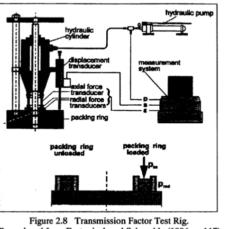
Displacement on the Rollers... Product Bed Offset... Run-Out Measurements, Discharge End Seal... Run-Out Measurements, Discharge End Seal, Close-up of One Cycle. Example of Rotary Dryer with a Conical End... Lifters Weight Modeling... . Product Weight Modeling... Rollers Modeling... Chain Tension Modeling... FEA Results; Deformation at the Sealing Surface under Simulated Operating Conditions... Fabrication Defect Solution #1... Fabrication Defect Solution #2... Representation of the Radial Operational and Alternating Defects... Representation of the Radial Operational and Alternating Defects... Platelets Seal Schematic... Cloth Composite Labyrinth Lip Seal Schematic... Polymeric Seal Section Examples... Burgmann Radial Packing Seal Schematic... Floating Stuffing Box Seal Schematic... Stuffing Box Representation and Terminology... . Radial Stress Distribution Representation... . Transmission Factor Test Rig... Friction Coefficient Test Rig...
Figure 2.10 Friction Coefficient Measurement Test Rig... 54
Figure 2.11 Transmission Factors Measurements Test Rig...54
Figure 2.12 Permeability Measurements Test Rig... 56
Figure 2.13 Leak Measurement Test Rig... 57
Figure 2.14 Pin-On-Disk Wear Rate Measurement Method... 60
Figure 2.15 Pin-On-Ring Wear Rate Measurement Method...61
Figure 3.1 Required Seal Absorbed Deformation in a Rigid Housing Case... 66
Figure 3.2 Seal Absorbed Deformation in a Flexible Housing Case... 67
Figure 3.3 Flexible Radial Compression System Schematic... 67
Figure 3.4 Radial Force Resulting from Flexible Member Applied Tension...68
Figure 3.5 Test Rig Flexible Housing Schematic...68
Figure 3.6 Tensioning Cable Arrangement...69
Figure 3.7 Flexibility of the Laced Cable Flexible Housing... 70
Figure 3.8 Radial Compression of Stacked Packing Braids... 71
Figure 3.9 Silicone Core Packing Braid...72
Figure 3.10 Test Series #1 Seal Arrangement #1... 73
Figure 3.11 Test Series #2 Seal Arrangement #2...74
Figure 3.12 Test Series #3 Seal Arrangement #3...74
Figure 3.13 Final Seal Design... 75
Figure 3.14 Test Rig General Arrangement...76
Figure 3.15 Opposed Seal Arrangement... 77
Figure 3.16 Foot Mounted Housing...78
Figure 3.17 Foot Mounted Housing, Exploded View... 78
XIV
Figure 3.19 Tensioning System Section View... 80
Figure 3.20 Deformable Drum Mechanism... 82
Figure 3.21 Deformable Drum Mechanism, Exploded View...82
Figure 3.22 Test Rig Electrical and Control Components...84
Figure 3.23 Pneumatic System Schematic... 85
Figure 3.24 Test Rig Instrumentation...86
Figure 3.25 Seal Thermocouple Location... 87
Figure 3.26 Seal Behaviour Typical Run-out Graphic...88
Figure 3.27 Forces on a Band-type Brake...90
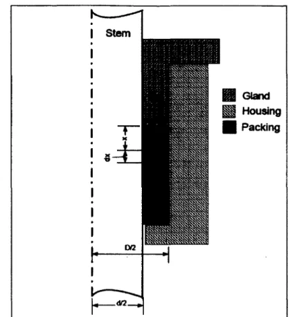
Figure 3.28 Forces Equilibrium on a Packing Element... 92
Figure 3.29 Radial Pressure Distribution for Several Friction Coefficients (Ro=6in) 94 Figure 3.30 Radial Pressure Distribution for Several Friction Coefficients (Ro=600in)... 96
Figure 4.1 Picture of the Test Rig as Built...99
Figure 4.2 Picture of Drum Thickness Reduction Close to the Welded Square B ars... 101
Figure 4.3 Run-Out Graphic of the Deformed Shaft... 102
Figure 4.4 Test Sequence Diagram... 106
Figure 4.5 Leaks as a Function of Gas Pressure, Seal Radial Applied Pressure and Temperature... 108
Figure 4.6 Leaks in Function of Gas Pressure, Seal Radial Pressure and Temperature; Test at 330*F and 105 psi Radial Pressure...109
Figure 4.7 Leaks in Function of Seal Radial Contact Pressure, Gas Pressure and Temperature... 110
Figure 4.8 Percentage of Leak Decrease in Function of Seal Radial Contact Pressure, Using Radial Pressure at 100 psi as the Reference... I l l Figure 4.9 Leaks as a Function of Temperature, Seal Radial Contact Pressure and Gas Pressure... 112
Figure 4.10 Arrangement #1: Example o f Drum Deformation Run-Out and Seal
Outside Displacement in Function of Drum Angular Location...114 Figure 4.11 Arrangement #2: Example o f Drum Deformation Run-Out and Seal
Outside Displacement in Function o f Drum Angular Location... 115 Figure 4.12 New Arrangement #3 Seal Disposition...117 Figure 4.13 Arrangement #3: Example of Drum Deformation Run-Out and Seal
Outside Displacement in Function of Drum Angular Location...117 Figure 4.14 Example of Cold Start-Up Torque Change...119 Figure 4.15 Motor Absorbed Torque in Function of Gas pressure, Temperature and
Radial Contact Pressure... 120 Figure 4.16 Picture of the Lip Created by the Packing Braids Extrusion...121 Figure 4.17 Dynamic Friction Coefficient in Function of Gas Pressure, Temperature
and Radial Contact Pressure... 122 Figure 4.18 Motor Torque vs Radial Applied Pressure and Drum Rotation Speed...123 Figure 5.1 Full Scale Application Proposed Seal Arrangement... 127
LIST OF ABBREVIATIONS AND ACRONYMES
FEA Finite Element Analysis PTFE Polytetrafluoroethylene
UHMW-PE Ultra High Molecular Weight Polyethylene
EG Expanded Graphite
0.1 Rotary Processors
Rotary dryers and processors are used in a wide variety of industries such as corn, wheat, sugar, wood chips, fertilizers, mining and minerals. The rotary dryer is the heart of the drying plant. Basically, an air or gas stream is heated and is sent at a predefined flow through a horizontal rotating drum. The product to be dried is fed into the rotating drum with a chute or a screw conveyor. The product dries before it reaches the other end of the rotating drum and falls into a collecting hood.
A R OUTLET (TO OTHER EQURMENT)'
CO U EC H N G
HOOD-FIXED THE-FLOATING TRE
FEED END
SEAL-PRODUCT M E T CHUTE-HOT A R DUCT-DGCHARGE -THRUST ROLLER SUPPORT BASE -DRIVE BASE ROLLER SUPPORT BASE____________ ROTATING DRUM -HOT ARM LET
(FROM OTHER EQUIPMENT)
2
Internal blades inside the rotating drum, called lifters, drag the product to the top quadrant of the drum in order to drop and disperse it into the gas stream. The drying takes place as the product tumbles along the bottom of the drum, and showers through the airstream while absorbing heat from the process gas and metal surfaces. The diameter of rotating drums can vary from 1.2 to 7.3 meters (4 to 24 feet) and their length can be up to 36.5 m (120 ft). They are generally made of mild steel, stainless steel or duplex stainless steel. The rotating drum rolls on two massive rings called tires. They are generally made of forged alloy steel or mild steel.
Each tire is supported by a pair of rollers made o f alloy steel, mild steel or nylon. One tire (fixed tire) is fixed with a thrust rollers and the other (floating tire) is free to move axially to allow for thermal expansion.
-THURST RO U £R -THRUST ROUER
SUPPORT BASE
Since there is a forced airflow through the drum, there is a pressure difference from the air inlet to the outlet of the drum, and consequently between the inside volume of the drum and its surrounding atmosphere. Therefore, due to the continual rotation of the drum, a dynamic seal is needed to prevent gas leaks between the rotating and non-rotating components at both ends. These seals will be the subject of a thorough study in this thesis.
0.2 General Statement of the Problem
Within any industrial plant, dryers are huge energy consumers. Any increase in drying efficiency, such as by properly sealing the ends of a rotary dryer, can lead to significant energy savings. Over the last few decades, acceptable sealing solutions were found to obtain a tolerable level of leaks when the dryers operated at near atmospheric pressure. In this new millennium, energy conservation is, more than ever, one of the driving forces behind any industrial project. In some promising industries, the use of pressurized rotary processors could lead to important energy savings and recovery. This thesis explores the possibility of sealing large processors, 3 to 4.5 m in diameter (10 to 15 ft), and up to 1 atmosphere gauge (14.7 psig) with the use of a conventional sealing technique.
Large rotating processors such as rotary dryers, kilns and rotary conditioners are not easily sealable because of the following issues:
1. These large vessels can process a wide variety of products. Some of them can be:
• abrasive, • corrosive,
• comprised of very fine particles, • sticky and deposit easily.
2. The process gas used to dry or condition the product can be from ambient temperature to red glowing steel temperatures. The high temperature dryers would be refractory lined
4
and more commonly called kilns. The resultant steel temperature around the seal location and along the whole vessel will affect the design of the seal. The following thermal issues will be reviewed:
• gas temperature, • metal temperatures,
• axial thermal growth from ambient to operating temperature, • radial thermal growth from ambient to operating temperature.
3. The severe process conditions are coupled with fabrication issues of thin walled large vessels. The rotating drum is an assembly of rolled and welded plates. Fabrication inaccuracy can result in the following defects:
• non-concentricity defect; sealing surfaces axis is off center from the tire axis, • out-of-roundness defect; the rolled surfaces can result in an oval shape, • run-out defect; imperfection of the surface such as a bump or a hole.
4. Beside fabrication tolerances, defects and thermal issues, the rotating vessel can suffer from deformations, misalignment and distortions due to different loads such as:
• axial displacement from the drum floating between the thrust rollers, • installation misalignments,
• local drum deformation due to non-uniform product loading, • drum deformation due to its dead weight.
The rotary processor seal needs to overcome these challenges while a proper rotary processor design, fabrication, and installation will reduce the defects and deformations to a minimum.
0.3 Primary Goal of the Study
The primary goal of this study is to find a simple and economically viable solution to seal a large rotating processor operating under low positive pressure of 0.069 to 0.138 MPag (10 to 20 psig). The proposed seal should be adaptive as it could be used for several different applications of varying product, temperature and pressure. It should overcome surface defects and deformation in order to achieve a proper seal; thus leaks should be reduced to an acceptable level at positive pressure. An acceptable level of leaks represents leaks less than one percent of the dryer inlet airflow.
0.4 Organization of the Dissertation
To achieve the main objectives of this study, this dissertation is dissected into five chapters;
1. Chapter 1 contains a Preliminary Study; a typical non pressurized rotary dryer is studied thoroughly against its fabrication methods, its installation and its operating factors. Measurements are performed on an operating dryer and the defects are quantified. Also, a finite element analysis is conducted in order to quantify the defects or deformations that cannot be measured.
2. Chapter 2 is dedicated to a Literature Review; first, the rotary processor conventional seals are reviewed against what is found in the preliminary study. Throughout the reviewed seals, the most promising concepts will be studied more deeply through a typical literature review.
3. Chapter 3 deals with the Seal and Test Rig Design; from the knowledge gained in the previous chapters, a new seal design is proposed. Its advantages and disadvantages are discussed and a test rig is developed to validate the new design. The methodology used and the capabilities of the rig are also described.
6
4. Chapter 4 gives the preliminary Experimental Tests results; once the test rig is built, a series of tests are performed and the functionality of the new seal design is quantified and discussed.
5. Chapter 5 summarizes the findings of this research and transposes them to the industrial application. The industrial applicability of the seal concept is discussed.
6. Finally the conclusion and recommendations are given on the viability of the concept and on the required studies to be performed before industrial application.
PRELIMINARY STUDY
1.1 Rotary Processor Methods of Fabrication
In order to design the appropriate seal for the drum it is important to understand the fabrication method used to build such equipment. Through the following sections, the methods of fabrication related specifically to the rotary dram assembly are described.
1.1.1 Rolled Plates
The rotating drum of the processor is made from rolled plates butt welded together to form short cylinders as shown in Figure 1.1. Depending on the drum diameter and the gross plate size, the short cylinders can be formed using one or two plates. Each short cylinder has one or two longitudinal welds. A number of short cylinders are welded together to form a long cylinder known as the drum. Longitudinal welds are staggered. The thickness of the drum varies along the drum length; it is usually thicker at the tire locations where the weight of the drum is supported. The thickness of the plates can vary between 6 to 50 millimeters (1/4” to 2”) depending on the application and dram diameter.
8
TRE ROUJNG SURFACE (REFERENCE) SEAUNG SURFACE
o
Figure 1.1 Rotary Drum Roiled Plates Schematic.
1.1.2 Welded Internals
Inside the rotary dryers, blades are installed around the shell as presented in Figure 1.2. These blades are more commonly called “lifters” because they lift the product from the rolling bed at the bottom of the drum to the top quadrant from where it is dropped and dispersed into the air stream for efficient drying. Many different shapes and types of lifters are used and have different methods of attachment to the shell. They can be bolted, but in most cases they are welded directly to the shell. Welded lifters create local deformation of the shell because residual stresses are generated by the welding process.
Figure 1.2 Rotary Drum Internals Schematic Example.
1.1.3 Tire Mounting
Usually, rotary dryers are supported by two tires. Some very long kilns can be supported by three tires or more. The tire is an annular ring fitted over the shell and acts as a ring stiffener. The tire rolling surfaces are used as a reference surface for alignment. Therefore, it is important that the surfaces are free of defects that can harm the proper function of the drum. There are different ways to mount the tires onto the shell. The most common of which are; machined pads, shimmed pads and shimmed casted chairs. In all cases the alignment of the axis of rotation of the tires with the axis of the shell is an important task to achieve during fabrication.
10
1.2 Methods o f Fabrication Resulting in Sealing Surface Defects
The basic methods used to fabricate large thin walled cylinders can produce many different defects. The sealing surface defect, where the gap between the sealing surfaces is not uniform around the circumference throughout a revolution of the drum, is one of them. It can be characterized into separate types such as the drum being out of roundness, non-concentric with the tire reference surfaces, local run-out and misalignment of the turning drum with the fixed portions of the seals.
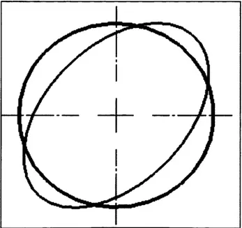
1.2.1 Out of Roundness
The out-of-roundness defect is caused by the rolling method used to give to the plates a circular shape. The resulting shape of the rolled plate can be oval, egg shaped or even includes comer shapes if the cylinder is formed using multiple plates welded together. The fabricator’s meticulous manipulation of these plates is very important, since an improperly braced thin walled cylinder lying horizontally can deform plastically by its own dead weight. This would result in an oval shape or egg shape as shown in Figure 1.3.
Once installed, the out-of roundness of the drum can be evaluated using a test indicator with a rolling pin. The test indicator is rigidly fixed to the base while the rolling pin is pressed against the shell. As the drum rotates, the indicator gives the local deformation. The readings can be transferred onto a graphic of local displacement (or run-out) as a function of the angular location. Since the run-out measurement is the primary technique to quantify defects, these will be presented on a 360° graphic around the circumference in order to trace them easily. Typical out-of-roundness defect graphic is presented below in Figure 1.4.
Out-of-Roundness Defect
1.5 R un-out reading 0.5 3 oc 9D l i 10; 2 0 31 iO -0.5 -1.5A ngular L ocation (deg)
Figure 1.4 Out-of-Roundness (oval) Typical Run-out Reading.
1.2.2 Non-Concentricity
The non-concentricity of the sealing surfaces can be caused by several factors. The rolling surfaces of the tires are used as the reference surfaces. If the tires are improperly shimmed, the whole shell can turn off-centered as shown in Figure 1.5. Therefore, the sealing surface will be non-concentric with the fixed part of the seal and the typical run-out is shown in Figure 1.6.
12
Figure 1.5 Non-Concentricity at Tire Installation
Non-Concentricity Defect
1.5 R un-out reading 0.5 ? c 3 tc li so 2 '0 31 iO -0.5 -1.5A ngular Location (deg)
Figure 1.6 Non-Concentricity Typical Run-out Reading
The non-concentricity defect can also come from an axis misalignment when the small cylinders are welded together to form the drum as presented in Figure 1.7.
SMALL C Y t M »
Figure 1.7 Non-Concentricity at Small Cylinder Assembly.
During the small cylinder assembly, another fabrication imprecision can occur. The small cylinders can be welded together with an uneven gap between any two adjacent cylinders. If the larger gaps were to be all at the same quadrant, the shell would have a banana shape as shown below in Figure 1.8.
— DRUM TOTAL LENGTH
CONTACT UNE SEAUNG CONTACT
14
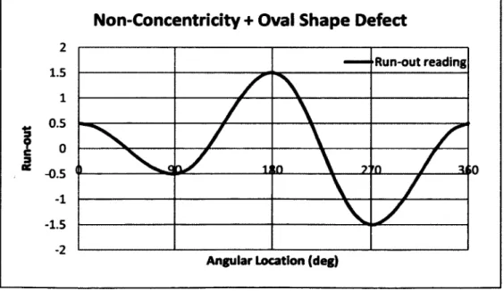
If the drum has such a shape, the sealing surface will surfer of a combination of a non concentricity and an out-of-roundness defect. Figure 1.9 and Figure 1.10 represent this potential defect.
OVAL SHAPE SEAUNG SURFACE
SEAUNS CONTACT UNE
Figure 1.9 Non-Concentricity and Oval Shape from Banana Shape.
Non-Concentricity + Oval Shape Defect
— R un-out reading 1.5 0.5 5 -0.5 Z ’£L -1.5 A ngular L ocation (d eg )
1.23 Local Run-out
The run-out defect is usually known as the overall maximum displacement over an entire circumference. Here, the local run-out defect shown in Figure 1.11 is a local defect that can have a concave or a convex surface.
Figure 1.11 Local Run-Out Defects.
Local run-out defects can be caused by the fabrication processes. The source of this type of defect is the longitudinal butt welds of the rolled plates. Depending on the welding procedure, the residual stresses created by the weld cause local deformation of the plate at the vicinity of the welded joint.
16
GRINDED LONGITUDINAL WELD
Figure 1.12 Run-out Defect, Longitudinal Weld.
Similarly when an internal feature, such a lifter, is welded inside the shell, local deformation occurs near the weld.
LIFTER-LONGUUDMALWEIQ
Figure 1.13 Run-out Defect, Lifter Longitudinal Welds.
Also, during fabrication, bracings are installed to prevent the shell from deforming under its dead weight. Even though their presence helps prevent gross deformations, this technique cannot avoid local distortions and smaller deformations, especially when subsequent operations are conducted near the braced section.
DRUM SHELL (DEFORMED)
/-D R U M SHELL / (THEORICAL) BRACING
18
Bracing Defect
R un-out reading 0.8 0.6 0.4 0.2 4* ? c 3 tc -0.2 -0.4 -0.6 -0.8A ngular Location (deg)
Figure 1.16 Typical Run-out Readings after Bracing Installation.
1.3 Installation Misalignments
During installation of the components surrounding the rotating drum, some imperfection may occur in the vertical and horizontal alignment of the fixed component of the seal and the rotating sealing surface. These misalignments need to be taken into account as they could add up to other defects. The acceptable tolerance is usually 0.79 mm (0.0313 in) in each direction, which would result in a misalignment of 1.12 mm (0.044 in)
1.4 Operation Factors
Beside fabrication defects, some operation factors are to be considered. Operation factors are displacements or deformations created during the processor operation.
1.4.1 Self Weight Deformation
Since the drum shell is made of thin plates, the upper quadrant will sag under its dead weight as shown in Figure 1.17. The shell deformation will take an oval shape, with the upper and
lower quadrants always being slightly flattened due to the rotation of the drum. Since this is an in-service deformation, one point of the surface will follow an oval trajectory and run-out measurements will not depict the defect.
THEORETICAL DRUM DIAMETER DEFORMED DRUM
Figure 1.17 Self Weight Operational Deformation.
1.4.2 Thermal Expansion
An important parameter to consider in a rotary dryer is, obviously, its high temperature. The differential thermal expansion between the cold state and the operating temperature of the dryer components in the vicinity o f the seal needs to be considered in the seal design to provide enough flexibility to absorb those defects and prevent any contact between the metallic components. Thermal expansion will occur in radial and axial directions. The radial direction is the diameter expansion and is presented in Figure 1.18.
20
Figure 1.18 Radial Direction Thermal Expansion.
The diameter expansion can be expressed by the following equation;
Arth = roAT (1.1)
Where;
Afth = Radial thermal expansion [in] [m]
r = Initial cold state drum average radius [in] [m] a = Thermal expansion coefficient [in/in/°F] [m/m/°C]
AT = Temperature variation between operating and initial state [°F] [°C]
The expansion in the axial direction is the distance change between the fixed tire and the seal due to temperature change as shown in Figure 1.19.
-SEAL
^/-ROTATING DRUM
8
4
EXPANSIONFigure 1.19 Axial Direction Thermal Expansion.
The axial expansion can be expressed by the following equation;
A l a x ia l .F E = IfE 0^
A la x ia l .D E = IdE ^ T
Where;
Alaxiai.FE = Axial expansion at feed end seal [in] [m]
A la x ia i.D E = Axial expansion at discharge end seal [in] [m]
lFE = Distance between feed end seal and fixed tire centerlines [in] [m]
lDE = Distance between discharge end seal and fixed tire centerlines [in] [m]
o = Thermal expansion coefficient [in/in/°F] [m/m/°C]
AT = Temperature variation between operating and initial state [°F] [°C]
(1.2) (1.3)
Before being able to estimate the thermal expansion, the shell temperature needs to be known. On-site measurements described in Section 1.5.2 give some indications on the operating temperature of the shell.
22
1.4.3 Displacement over the Rollers
The axial displacement of the drum is restrained by thrust rollers. In effect, one of the tires is placed between two horizontally fixed rollers to prevent axial movement. During drum installation, the thrust rollers are set with a predefined gap between the thrust roller and the side face of the fixed tire. Usually, a properly aligned drum will turn without coming into contact with the two thrust rollers; this is the common strategy to minimize wear on the tire and on the thrust rollers. The size of this gap will eventually result in an equivalent axial displacement at the seal locations:
fiTR = 2 x Utr-t (1*4)
Where;
(XTR = Axial displacement over the rollers [in] [m]
Utr-t - GaP between the tire side face and the thrust roller face [in] [m]
SEAL /-R O T A T IN G DRUM
/
— It -■ 5 ■ ■ ■ s ■ - M - i1.4.4 Product Load Distribution Effect
Due to the combined effect of the drum rotation and the internal lifters, the processed product is dragged up to one side of the drum. This forms a rolling bed of product on one side of the drum which will deform the shell as shown in Figure 1.21.
-DRUM SHELL (THEORETICAL} y-DRUM SHELL / (DEFORMED) ■PRODUCT jfe&TOfo______
PSIST
FAX 3 ' A XFigure 1.21 Product Bed Offset.
The magnitude of the induced deformation varies with the product load inside the drum. Furthermore, the processor can run at its full capacity but also at a reduced capacity, creating a variable product load over a long period of time. As with the dead weight defect, this cannot be depicted by run-out measurements.
1.4.5 Internal Pressure
In addition to the previously noted factors, the new pressurized drum is subjected to deformation created by the dryer gas pressure. The drum experiences a radial expansion that depends on the thickness and the radius of the drum at the seal position. From the basic stress
and strain relationship or Hooke’s law, it is possible to express directly the radius variation caused by an internal pressure. For the case of an open cylinder the radial growth is given by:
t o p r e s s - tE
P r2
(1.5)
Where;
= Radius variation from an internal pressure [in] [m] = Internal pressure [psig] [MPa]
= Shell average radius at seal location [in] [m] = Shell thickness at seal location [in] [m] = Young’s modulus [psi] [MPa]
P r
t E
1.5 Onsite Measurements
During the preliminary study, measurements were performed on an operating dryer. The studied dryer was 4.572 m (15’-0”) diameter by 17.983 m (59’-0”) long and made of stainless steel 304L. Its inlet gas temperature was about 454 °C (850 °F) with rotating speed of 4 RPM. The seal installed is a Kevlar labyrinth lip seal rubbing directly onto the shell external surface.
1.5.1 Run-Outs
Run-out measurements were performed at the discharge end of the drum using an electronic test indicator. A roller bearing was installed on the tip of the tool to facilitate the readings. The indicator was connected to a computer for a continuous monitoring at a rate of 20 readings per seconds. The discharge end seal surface was the object of the study. Three to four turns of the drum were recorded for the repeatability of the measurements and are shown in Figure 1.22.
Discharge Seal Plate 15.88 mm (5/8" thk)
1.2 1 0.8 0.6I 0.4
0.2 0 -0.2I
5
Run-out fm) O n e cy cle Time (sec)Figure 1.22 Run-Out Measurements, Discharge End Seal.
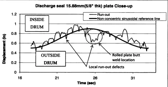
If the study is conducted on one cycle, Figure 1.23 reveals two types of defects; local run-out and non-concentricity.
c E
Discharge seal 15.88mm(5/8" thk) plate Close-up
1.2 R un-out
N on-concentric sinusoidal re fe re n c e line
INSIDE 1 DRUM 0.8 0.6
0.4
R olled p la te b u t t w e ld lo c a tio n OUTSIDE 0.2 DRUM Local r u n - o u t d e f e c ts 016
2126
31
Time (sec)26
The first depicted defect is the local run-out. The local run-out defect is caused in this case by the weld residual stresses. The analysis of the curve of Figure 1.23 points to the fact that there is a lifter welded inside the drum corresponding to each peak on the run-out curve. The lifters were welded continuously on each side and were installed parallel to the drum rotating axis. Effectively, 18 lifters were welded and 18 peaks can be counted. The magnitude of this local defect is approximately 6.35 mm (0.250 in). Also, the largest local run-out defect was located at the butt weld of the rolled plate. This weld is parallel with drum rotating axis and is a multiple pass weld. This type of weld generates great internal stress and tension which may be the cause of the greater deformation in this location. The magnitude of this local defect is approximately 9.53 mm (0.375 in). These two types o f deformations create a discontinuity resulting in a non smooth sealing surface and are to be avoided to achieve a tight seal.
The second defect is related to non-concentricity. It is difficult to determine the cause of this defect since many fabrication and installation defects can be the cause. With only the measurements taken, it is impossible to determine the exact origin of this defect. Possible causes might be non-concentric sections, axis misalignment of the tires and shell and shell banana shape deformation.
The maximum defect magnitude is 14.53 mm (0.572 in). It is important to note that no specific fabrication procedures were requested to obtain greater precision on the sealing surface. Thus the magnitude of the defect is probably the worst case condition for a sealing surface of a drum of this diameter.
Also, since the run-out measurements are taken at a fixed location, the oval shape created by the product loading and the vessel self weight cannot be isolated. To quantify this deformation, a finite element analysis was performed. The details of this analysis are presented in Section 1.6.
1.5.2 Shell Temperatures
Shell temperatures have been taken on two very different rotary dryers. The first is a light duty rotary dryer used in the corn industry. Its inlet temperature is close to 484°C (900°F). The shell thickness is 15.9 mm (0.625 in). The second dryer is used in the mining industry and is known as a heavy duty rotary dryer. Its inlet temperature is close to 1083°C (2000°F). The shell thickness is 25.4 mm (1 in). Even though these applications are very different, the measured operating shell temperature for both dryers is between 100 and 120°C (212 and 250°F).
The product to be dried is fed to the rotary drum normally at near ambient temperature with moisture content anywhere between 3% and 40% by weight. It forms a bed which covers almost a quarter of the internal drum circumference. The heat absorbed by the shell through convection of the internal dryer gas is transferred readily by conduction to the product concentrated at the bottom of the drum. Thus the shell is cooled by the product and the product heated by the shell. At the inlet, the gas is very hot and the product is cold and wet. At the outlet, the gas is cooler, while the product is hotter and dry. The whole process results in a near uniform shell temperature along the length of the shell.
1.6 Vessel Finite Element Analysis (FEA)
Deformations created by the product weight and by the drum dead weight alternate with the drum rotation and are therefore not depicted if the measurement tool is located at a fixed point, such as the dial gauge used to measure the run-outs. To quantify these defects, a numerical approach has been used. This was achieved by performing a finite element analysis (FEA) on a typical light duty rotary dryer. The sealing surface was studied to determine the total out-of-roundness defect created by the product weight and by the drum self weight.
28
Basically, the 4.572 m (15 ft) diameter rotary dryer, on which the run-out measurements were taken, was modeled using a 3D software program (SolidWorks 2008). The feed end shape of the drum was modified slightly to a conical shape as shown in Figure 1.24, which is the desired configuration of the pressurized dryer. The simulation was done using a commercial finite element analysis program (CosmosWorks 2008).
Figure 1.24 Example of Rotary Dryer with a Conical End.
1.6.1 Simplifications, Loads and Boundary Conditions
Because the rotation speed is low and the dynamic effects are negligible, a static analysis was performed on the drum. For simplification, only the drum shell and the tires were modeled. The internal lifters were not modeled but their weight was replaced by an equivalent vertical force at their location around the drum circumference as shown in Figure 1.25.
Also the product weight was replaced by a vertical force applied to approximately one quarter of the circumference which represents the area covered by the bed of product during normal operation is shown in Figure 1.26.
Figure 1.26 Product Weight Modeling.
The rollers were constrained from displacement in the radial direction as shown in Figure 1.27 and the drum was allowed to rotate freely about its axis.
30
Figure 1.27 Rollers Modeling.
The chain pull was replaced by a virtual link; a virtual link is a rigid beam connected at its pivoted ends. One end was connected to the last engagement tooth of the chain wheel and the other end was fixed in space on a ring modeled around the drum as shown in Figure 1.28. The virtual link creates a counter force to balance the moment produced by the product weight and, therefore; prevents the drum from rotating around its axis.
Figure 1.28 Chain Tension Modeling.
Finally, one nodal point at the discharge end tire was blocked in the axial direction to avoid singularity.
1.6.2 Mesh
The model mesh was generated using two types o f elements. 2D parabolic triangular elements were used to model the shell and all thin plates while 3D tetrahedral elements were used for the other parts such as the tires, the tire support pads and the simplified chain wheel.
1.63 Deformations at Seal Location
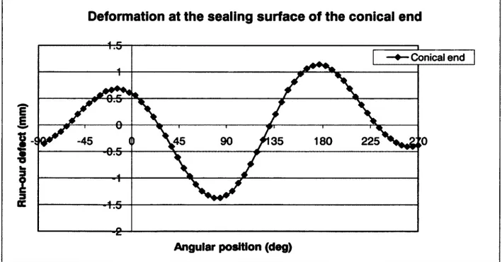
The deformations of the drum resulting from its dead weight and the product load obtained from this analysis are very important as they are added to the fabrication defects to design the seal. In the graphic below, the sealing surface deformed shape obtained from the FEA show a trend similar to the run-out measurement although it could not be measured using the rolling test indicator. Figure 1.29 shows the change in the radius as a function of the circumference at the seal location near the conical end.
Deformation at the sealing surface of the conical end
Conical e n d
E
gi
-45 .45 35 180 225 ■0^ 3 KAngular position (deg)
Figure 1.29 FEA Results; Deformation at the Sealing Surface under Simulated Operating Conditions.
32
The maximum deformation around the circumference is close to 2.49 mm (0.098 in). Also, the graphic shows two combined defects; non-concentricity and out-of-roundness (oval shape). Each defect can be quantified separately with the information shown in the graphic. The 0° on the graphic represents the top quadrant of the drum. Half of the subtraction o f the run-out reading at 0° and 180° gives the vertical non-concentricity. Also, half of the subtracted run-out reading at 90° and 270° gives the lateral non-concentricity. The vertical and lateral non-concentricity defects are respectively equal to -0.28 mm (-0.011 in) and 0.47 mm (0.018 in). The resultant non-concentricity defect is then 0.55 mm (0.022 in).
The out-of-roundness defect is the addition of the average of the two positive peaks and the absolute average of the negative peaks. The out-of-roundness defect is found to be equal to 1.78 mm (0.070 in).
1.7 Discussion
Fabrication defects are the most unpredictable and most important defects as shown in Table 1.1.
Table 1.1 Fabrication Defects Summary
Fabrication defects Causes Estimation
methods
M agnitude Local defect Welded internal components On site run-out
measurements
Max. 6.35 mm (0.250 in) Local defect Butt welded rolled plates On site run-out
measurements
Max. 9.53 mm (0.375 in) Non-concentricity Tire non-concentricity with
shell, shell rolled plates assembly, shell banana shape
On site run-out measurements Max. 6.35 mm (0.250 in) Combined fabrication defects On site run-out measurements Max. 14.53mm (0.572 in)
Fabrication techniques can vary from a fabricator to another and also can vary with the type of steel used. Obviously, the magnitude of the defects also increases with the size of the drum. For the operating dryer studied in the previous sections no high precision fabrication procedures were specified. The defects measured can probably be considered to be a worst case condition. Despite this assumption, any fabrication procedure that creates local deformation on the sealing surface needs to be dropped. A smooth and even sealing surface needs to be obtained and two solutions are proposed to resolve this issue;
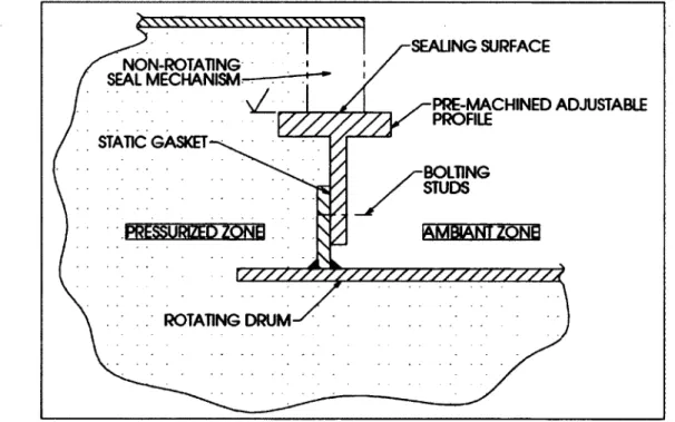
• Solution #1; a separately machined “T” shape ring could be bolted to the imperfect shell as shown in Figure 1.30. SEALING SURFACE NON-ROTATING SEAL MECHANISM PRE-MACHINED ADJUSTABLE STATIC GASKET BOLTING STUDS V / / / / / / / / / / / / / / / / . ROTATING DRUM
Figure 1.30 Fabrication Defect Solution #1.
The ring needs to be delicately aligned during the drum installation. Once it is aligned, the bolting studs are tightened. The leaks between the profile and the rotating drum flange can be prevented using a static gasket. Also, the presence of the ring stiffens the end of the drum, thereby reducing both deformations and seal radial movement. Finally, the ring can be easily replaced if needed.
34
• Solution #2; after the drum is installed on the two rollers, the sealing surface can be rectified using a mobile lathe tool and/or a mobile rectifying tool.
NON-ROTATING
SEAL MECHANISM SEALING SURFACE
POST-INSTALLATION MACHINED PAD
^ ) / i W > ) / / > V / / / / / / / / / / / 7 Z
ROTATING DRUM
Figure 1.31 Fabrication Defect Solution #2.
In both solutions, the fabrication imperfections are overcome with a machined surface. The main difference between the two solutions is that with solution #2 the machining is the last step in fabrication of the drum. The final machining of the sealing surface is performed only once the drum is installed at the client site on its bases and fully aligned. The machining would, therefore; remove all the fabrication defects.
Although solution #1 requires precise alignment and solution #2 requires a final machining step, both are feasible and offer appreciable improvements to the continuity and quality of the sealing surface. Basically if one of these solutions is implemented, only the installation defects, the alternating defects and the operation defects will need to be overcome by the seal.
Using the processor geometry simulated in the FEA, all the other defects are quantified using Equations 1.1 through 1.5. These are the deformations that an improved seal design would still need to overcome.
• The thermal radial expansion (Eq. 1.1);
Aith = 0.066 in 1.68 mm
• Axial thermal expansion (Eq. 1.2 and 1.3);
Alaxial,FE = 1 .1 7 6 in 2 9 .8 8 mm Alaxtal.DE = 0 .2 4 2 in 6 .1 5 mm
• The axial displacement over the rollers (Eq. 1.4);
Mr* = 1 /8 in 3 .1 8 mm
• Radius variation from an internal pressure (Eq. 1.5); A*press = 0 .0 0 2 in 0 .0 5 mm
Where;
r = 38.25 in 0.972 m
a = 9.61 pin/in/°F 17.3 pm/m/°C (Stainless steel 304L)
AT = 180 °F 100 °C If e = 680.00 in 17.272 m Ids = 140.00 in 3.556 m Ut r-t = 1/16 in 1.588 mm P = 14.7 psi 0.1013 MPa t = 3/8 in 9.53 mm E = 27 550 ksi 190 GPa
• Radius variation due to drum dead weight and product loading (FEA results);
36
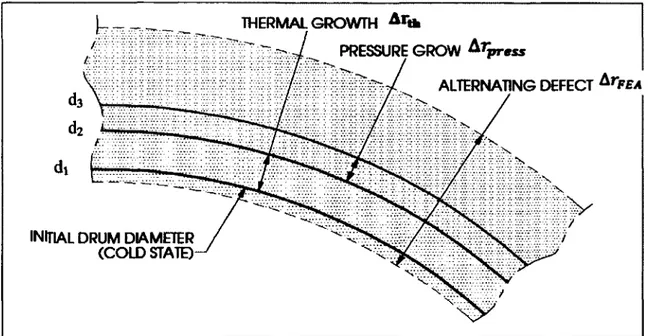
With each defect quantified for the studied example, the useful dimensions for the design can be identified. Two dimensions are particularly important in the design process. The first one is the sealing surface diameter (d j), as shown in Figure 1.32. For example, if solution #2 is implemented, the sealing surface diameter would be the final machined diameter of the pad. The second dimension required to design the seal properly is the operating nominal diameter(d3), as shown in Figure 1.32. This diameter has a tolerance represented by all the alternating defects such as those produced by the drum dead weight and the product weight obtained by FEA.
di = Sealing surface diameter [in] [mm]
d i = ^machined diam eter o f p ro f ile> f°r solution #1 (1-6)
d j = 2 x r + ^, for solution #2 (1.7)
d2 = Theoretical thermally expanded diameter [in] [mm]
d 2 = d i + 2 x Arfl, (1.8)
d3 = Nominal operating diameter [in] [mm]
d 3 = d2 + 2 x Arpress (1-9)
d 3 = dt + 2 x Arth + 2 x Arpress (1.10)
The diameters calculated above are for perfectly circular cylinders. In reality, as shown by the results of the FEA, the shape of the drum is not perfectly circular at the sealing surface. Therefore, a tolerance value is specified in order to define a diameter(£>3) that includes the imperfections and local defects.
D3 = Operating diameter range [in] [mm]
D3 = d3 ± ArFEA = [D3min; D3 max] (1-11)
THERMAL GROWTH A r«i
PRESSURE GROWTH ^ r\'press
ALTERNATING DEFECT & r F EA
INITIAL DRUM DIAMETER (COLD STATE)
Figure 1.32 Representation of the Radial Operational and Alternating Defects.
For the studied processor, here are the calculated diameters:
dt = 76.875 in 1952.6 mm
d 2 = 77.008 in 1956.0 mm
d3 = 77.012 in 1956.1 mm
D3 = [76.914; 77.110] in [1953.6; 1958.6] mm
Figure 1.32 shows the parameters discussed previously. It includes a small alternating defect in addition to the radial growth to pressure and temperature. However, this defect related to drum self weight and product loading may have a greater magnitude than the combination of the thermal and pressure expansion as they are not interdependent. The possible representation is shown in Figure 1.33:
38
THERMAL GROWTH A rtk
PRESSURE GROW 'press
ALTERNATING DEFECT a r FEA
INITIAL DRUM DIAMETER (COLD STATE)
X
Figure 1.33 Representation of the Radial Operational and Alternating Defects.
For this reason, the diameter range needs to be redefined in order to take into account this possibility.
Dmin = fnin(dx', D^pmin) (1*12)
And
D-max = ^3,max (1 -1 3 )
Finally, the diameter range of the sealing surface can be defined.
D = [76.875; 77.110] in [1952.6; 1958.6] mm
In addition, the total axial displacement can be calculated as follows:
For the studied processor, the calculated maximal axial displacement is:
A1 = 1.301 in 33.05 mm
Since the seal design is yet to be established, the seal housing temperature is considered to stay near ambient temperature. Indeed, in many cases, the dryers are installed outside and the seal housing may be cooled down by the wind. Thus, the housing inner diameter is considered not to expand; this corresponds to the worst case design scenario as the housing and drum shell would see the greatest thermal expansion differential.
During the start-up of the processor, the seal needs to be initially airtight as the pressure build-up is necessary for operation. For this reason, the seal requirements are grouped into two criteria. The first one is the maximal absolute radial displacement. It corresponds to the minimum required cold state radius difference between the sealing surface and the seal housing inner diameter. This value is used to determine the machining diameters of the sealing surface and the housing inner diameter.
A r seal,m ax = 2 s S C 2 s U » ( 1 . 1 5 )
The second one is the maximal out-of-roundness displacement. It is the maximal radial displacement over the sealing surface at one location on the seal during the operation. The thermal and pressure expansion are excluded since this value represents the maximal out-of- roundness defect at any instant of the dryer operation.
40
1.8 Summary of the Seal Surface Movements
The results of the seal surface movement requirements are summarized in Table 1.2. These values calculated in the previous section are part o f the design specifications that the designed seal needs to meet. Additional design requirements such as pressure, speed, temperature and maintenance will also be considered in the design of the seal.
Table 1.2 Seal Design Displacements Summary
Variable M agnitude
(in)
M aenitude (mm)
Axial displacement A1 1.301 33.05
Radial maximal seal absolute displacement
Ar seal,max 0.118 2.98
Radial sealing surface maximal out-of-roundness displacement
LITERATURE REVIEW
2.1 Introduction
The literature review is composed of two sections. Section 2.2 describes the most common seals used nowadays in the rotary processing industry. Section 2.3 summarizes a collection of papers on packing seals.
2.2 Common Rotary Processor Seals Review
Currently in the rotary processing industry, many different types of seals are used for different applications. Each seal has its qualities and limitations. However, none of them can sustain appreciable positive pressure without leaking. The following section provides a general description of each concept along with the main advantages and disadvantages.
2.2.1 Platelet Seal
The platelet seal is mainly used in the very high temperature industries such as rotary kilns, where air inlet temperature exceeds 538°C (1000°F). This very robust design is conceptually a lip seal formed by a succession of metal plates cut and curved precisely to achieve acceptable continuous contact onto the sealing surface. The plates are usually spring loaded using a tensioning cable. Also, a replaceable wear band is installed at the sealing surface where friction is very high between the two metal rubbing surfaces.
42 -T-nSiQM NC C a 3 lE Gunt ORUM HOOD riXXiBLE SEAUKG PLATELETS
Figure 2.1 Platelets Seal Schematic1.
This design has proved to be reliable to sustain high temperatures. Its main drawback is its inability to form a tight seal. The metal to metal contact surfaces and the joints between the plates reduce considerably its efficiency. As a result, this type of seal is used only in applications where the process gas is slightly under negative pressure.
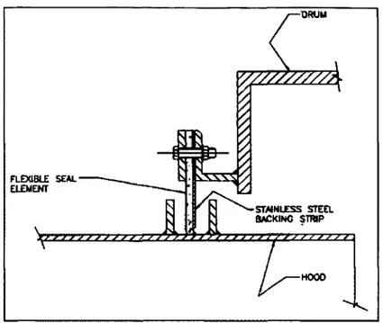
2.2.2 Cloth Composite Labyrinth Lip Seal
A composite labyrinth lip seal is formed by the arrangement of several plies of a composite cloth made of Kevlar fibers or glass fibers. In a labyrinth seal, the cloth rubs between two metallic ring surfaces. These rings prevent dust from accumulating at the bottom of the seal and create a tortuous path for air to escape from the drum or leak into the drum. The gap between these surfaces is given by the required axial displacement allowance. The cloth is held by a bolted flange with a metal backing strip to prevent the lip from being sucked inside the drum.
FLEXIBLE SEAL
ELEMENT
STAINLESS STEEL
b a c k in g s t r ip
HOOD
Figure 2.2 Cloth Composite Labyrinth Lip Seal Schematic2.
This type of seal has proved to be more efficient at reducing leaks than the platelet seal but is applicable only at lower temperature installations and is less robust. It is not suitable for slightly positive pressure applications because the lip is usually not sufficiently rigid. Furthermore, the contact between the sealing surfaces is uneven since the assembly of the cloth plies tends to create important leakage paths. This cheap design can be used in low temperature applications where a significant leak is still acceptable.
2 .2 3 Polymeric Seal
A polymeric seal is a continuous seal that can be made of several composite materials such as a combination of polytetrafluoroethylene (PTFE), rubber, carbon, bronze, ultra high molecular weight polyethylene (UHMW-PE), glass fiber etc... The cross section of the seal can vary depending on the application; lip seals are generally used for rotary applications. The rubbing surface material for this type of application would be made of a combination of
44
PTFE and carbon materials. A backing ring made of rubber could be used to absorb the imperfections of the sealing surface.
Figure 2.3 Polymeric Seal Section Examples.3
The principal limitation of this type of seal is the maximum allowable temperature. In a rotary processor application, the seal can be subjected to gas temperatures higher than 482°C (900°F). PTFE composites can only sustain temperatures up to 260°C (500°F). Also, rubber composites which would act as an imperfection absorber can only sustain temperatures up 200°C (400°F).
Manufacturers producing this type of seal are limited in number. The maximum diameter that can be produced in a composite made of PTFE and carbon materials is only 1.5 m (5 ft). This type of composite cannot be glued, welded or vulcanized. Therefore, the seal needs to be installed as a continuous ring which would complicate appreciably its replacement.
2.2.4 Vertical Contact Surface Packing Seal
Vertical contact surface packing seal is a solution proposed by the company Burgmann. Basically, four packing seals rub onto a ring perpendicular to the drum rotating axis. This design concept allows any radial displacement such like thermal expansion, or non
packing seals. Secondly, the axial displacements are absorbed by a flexible bellow. Thus, the non-rotating part of the seal moves axially with the drum. A few rolling guide supports are placed around the non rotating part to prevent rotation while allowing axial displacement.
This design appears to have great potential to sustain the required pressure. Its main drawbacks are the number of components that need to be disassembled to replace the packing seals and the number of bolts that need to be live loaded to maintain them tight. Also, it is well known that packing seals creep with time and, therefore; the use of Belleville washer is required to maintain the load. This design has proven to withstand an internal drum pressure of several millibars. If it was to be upgraded to achieve higher pressure by adding more packing rows, the number of components would increase drastically.
4 Reproduced from EagleBurgmann. « http://www.burgmann.com/ ».
concentricity to translate in the radial direction without applying the deformations onto the
VERTICAL CONTACT PACKING FLEXIBLE BELOW ROTATING DRUM FLEXIBLE BELOW
46
2.2.5 Floating Stuffing Box Seal
The floating stuffing box seal is a typical stuffing box set-up where the external housing for the gland is attached to a fixed component via a flexible bellow. This concept allows the whole seal arrangement to displace axially and, to a lesser degree, radially. Thus this reduces the amount of drum deformation applied directly onto the packing seals. This design easily handles many operating issues such as axial thermal expansion and movement. It also absorbs radial displacement change produced by non-concentricity and misalignment between the fixed casing and the rotating drum.
m.
wa N*.
ID 03.
Figure 2.5 Floating Stuffing Box Seal Schematic.
Regardless of the high degree of flexibility of this sealing arrangement, defects of the sealing surface such as out-of-roundness and run-out must be absorbed by the packing itself. Since packing seals have little capacity to recover their shape when exposed to alternating deformations these seals may struggle to maintain a seal when these imperfections are significant. This design is usually used up to a maximum internal drum pressure of 0.007 MPag (1 psig).