This is an author-deposited version published in:
http://oatao.univ-toulouse.fr/
Eprints ID: 10708
To link to this article: DOI: 10.1364/OE.22.001749
URL: http://dx.doi.org/10.1364/OE.22.001749
To cite this version: Kanesan, Thavamaran and Le, Son Thai and Roque,
Damien and Ellis, Andrew D. Non-rectangular perfect reconstruction
pulse shaping based ICI reduction in CO-OFDM. (2014) Optics Express,
vol. 22 (n° 2). pp. 1749-1759. ISSN 1094-4087
O
pen
A
rchive
T
oulouse
A
rchive
O
uverte (
OATAO
)
OATAO is an open access repository that collects the work of Toulouse researchers and
makes it freely available over the web where possible.
Any correspondence concerning this service should be sent to the repository
administrator: [email protected]
Non-rectangular perfect reconstruction pulse
shaping based ICI reduction in CO-OFDM
Thavamaran Kanesan,1,2,* Son Thai Le,1 Damien Roque,2 and Andrew D. Ellis1
1Aston Institute of Photonic Technology, Aston University, Birmingham B4 7ET, UK 2Telekom Research and Development, Cyberjaya, Selangor, Malaysia
2Grenoble Images Parole Signal Automatique (GIPSA-LAB), 11, Rue Des Mathematiques, 38402 Grenoble, France
Abstract: In this paper, we propose to increase residual carrier frequency offset tolerance based on short perfect reconstruction pulse shaping for coherent optical-orthogonal frequency division multiplexing. The proposed method suppresses the residual carrier frequency offset induced penalty at the receiver, without requiring any additional overhead and exhaustive signal processing. The Q-factor improvement contributed by the proposed method is 1.6 dB and 1.8 dB for time-frequency localization maximization and out-of-band energy minimization pulse shapes, respectively. Finally, the transmission span gain under the influence of residual carrier frequency offset is ~62% with out-of-band energy minimization pulse shape.
©2014 Optical Society of America
OCIS codes: (060.0060) Fiber optics and optical communications; (060.1660) Coherent
communications. References and links
1. Z. Benyuan, D. Peckham, Y. Man, T. Taunay, and J. Fini, “Recent progress in transmission fibers for capacity beyond 100-Tbit/s,” in Optical Fiber Communication Conference and Exposition (OFC/NFOEC), 2012 and the
National Fiber Optic Engineers Conference (2012), pp. 1–3.
2. Z. Jian and A. Ellis, “Advantage of optical fast OFDM over OFDM in residual frequency offset compensation,” IEEE Photon. Technol. Lett. 24(24), 2284–2287 (2012).
3. C. Simin, Y. Ma, and W. Shieh, “Multiband real-time coherent optical OFDM reception up to 110 Gb/s with 600-km transmission,” IEEE Photonics J. 2(3), 454–459 (2010).
4. X. Zhou, K. Long, R. Li, X. Yang, and Z. Zhang, “A simple and efficient frequency offset estimation algorithm for high-speed coherent optical OFDM systems,” Opt. Express 20(7), 7350–7361 (2012).
5. Y. Chun Ju, L. Xiang, S. Chandrasekhar, K. Yong-Hwan, K. Jong-Hoi, J.-S. Choe, C. Kwang-Seong, and N. Eun-Soo, “An efficient and frequency-offset-tolerant channel estimation and synchronization method for PDM CO-OFDM transmission,” in 2010 36th European Conference and Exhibition on Optical Communication
(ECOC) (2010), pp. 1–3.
6. A. Barbieri, G. Colavolpe, T. Foggi, E. Forestieri, and G. Prati, “OFDM versus single-carrier transmission for 100 Gbps optical communication,” J. Lightwave Technol. 28(17), 2537–2551 (2010).
7. N. Kaneda, Y. Qi, L. Xiang, S. Chandrasekhar, W. Shieh, and Y. Chen, “Real-Time 2.5 GS/s coherent optical receiver for 53.3-Gb/s sub-banded OFDM,” J. Lightwave Technol. 28(4), 494–501 (2010).
8. C. Simin, Y. Qi, and W. Shieh, “Demonstration of 12.1-Gb/s single-band real-time coherent optical OFDM reception,” in 2010 15th OptoeElectronics and Communications Conference (OECC) (2010), pp. 472–473. 9. T. Li, Y. Jianjun, Z. Junwen, S. Yufeng, and C. Nan, “Reduction of intercarrier interference based on window
shaping in OFDM RoF systems,” IEEE Photon. Technol. Lett. 25(9), 851–854 (2013).
10. W. Kozek and A. F. Molisch, “On the eigenstructure of underspread WSSUS channels,” in First IEEE Signal
Processing Workshop on Signal Processing Advances in Wireless Communications (1997), pp. 325–328.
11. D. Roque and C. Siclet, “Performances of weighted cyclic prefix OFDM with low-complexity equalization,” IEEE Commun. Lett. 17(3), 439–442 (2013).
12. W. Kozek and A. F. Molisch, “Nonorthogonal pulseshapes for multicarrier communications in doubly dispersive channels,” IEEE J. Sel. Areas Comm. 16(8), 1579–1589 (1998).
13. D. Roque, “Modulations multiporteuses WCP-OFDM: evaluation des performances en environment radiomobile,” PhD Dissertation (Universite de Grenoble, 2012).
14. J. Proakis and M. Salehi, Digital Communications (McGraw-Hill, 2006).
15. B. Farhang-Boroujeny, “OFDM versus filter bank multicarrier,” IEEE Signal Process. Mag. 28(3), 92–112 (2011).
16. T. Strohmer and S. Beaver, “Optimal OFDM design for time-frequency dispersive channels,” IEEE Trans. Commun. 51(7), 1111–1122 (2003).
17. D. Pinchon and P. Siohan, “Closed-form expressions of optimal short PR FMT prototype filters,” in 2011 IEEE
Global Telecommunications Conference (GLOBECOM 2011) (2011), pp. 1–5.
18. P. Siohan, C. Siclet, and N. Lacaille, “Analysis and design of OFDM/OQAM systems based on filterbank theory,” IEEE Trans. Signal Process. 50(5), 1170–1183 (2002).
19. S. Randel, S. Adhikari, and S. L. Jansen, “Analysis of RF-pilot-based phase noise compensation for coherent optical OFDM systems,” IEEE Photon. Technol. Lett. 22(17), 1288–1290 (2010).
20. A. Sano, H. Masuda, E. Yoshida, T. Kobayashi, E. Yamada, Y. Miyamoto, F. Inuzuka, Y. Hibino, Y. Takatori, K. Hagimoto, T. Yamada, and Y. Sakamaki, “30 x 100-Gb/s all-optical OFDM transmission over 1300 km SMF with 10 ROADM nodes,” in 2007 33rd European Conference and Exhibition of Optical Communication -
Post-Deadline Papers (published 2008) (2007), pp. 1–2.
21. D. Roque, C. Siclet, J. Brossier, and P. Siohan, “Weighted cyclic prefix OFDM: PAPR analysis and performances comparison with DFT-precoding,” in 2012 Conference Record of the Forty Sixth Asilomar
Conference on Signals, Systems and Computers (ASILOMAR) (2012), pp. 1065–1068.
22. W. Shieh, Q. Yang, and Y. Ma, “107 Gb/s coherent optical OFDM transmission over 1000-km SSMF fiber using orthogonal band multiplexing,” Opt. Express 16(9), 6378–6386 (2008).
23. Q. Dayou, H. Ming-Fang, Z. Shaoliang, P. Nan Ji, S. Yin, F. Yaman, E. Mateo, W. Ting, Y. Inada, T. Ogata, and Y. Aoki, “Transmission of 115×100G PDM-8QAM-OFDM channels with 4bits/s/Hz spectral efficiency over 10,181km,” in 2011 37th European Conference and Exhibition on Optical Communication
(ECOC) (2011), pp. 1–3.
1. Introduction
In the past years, coherent optical-orthogonal frequency division multiplexing (CO-OFDM) has been an attractive technology in high speed communication, due to its inherent advantages of higher resilience towards chromatic dispersion and polarization mode dispersion, flexibility in accessing individual subcarriers in multi-user environment, and a simplified equalization scheme [1]. However, apart from the disadvantage of high peak-to-average ratio (PAPR), the CO-OFDM is very sensitive towards carrier frequency offset (CFO) [2], which will effectively introduce inter-carrier interference (ICI).
In CO-OFDM transmission demonstration, CFO estimation and compensation was carried out in [3–5]. However, in high speed CO-OFDM systems, residual uncompensated CFO always exists with Gaussian distribution [2]. It is crucial to minimize the residual CFO to not only avoid ICI, but also relaxes the complexity of the initial CFO estimator and enhances the receiver robustness against optical local oscillator instability [2, 6]. However, the algorithms for ICI mitigation are computationally demanding, and the implementation of such algorithm is highly not feasible due to the high speed nature of optical communications [6]. For an example, some real-time CO-OFDM transmission demonstrations were not able to include even the first stage CFO compensation due to the lack of resources in field programmable gate array (FPGA) [7, 8], unless a state-of-the-art FPGA with high capacity was utilized as the CO-OFDM receiver as demonstrated in [3]. An efficient approach in mitigating the impact of residual CFO is to use pulse shaping techniques with good time and frequency localization properties. Recently Li et al [9] introduced pulse shaping with root raised cosine (RRC) in optical OFDM, where RRC has demonstrated some improvements in comparison to rectangular pulse shape for receiver operating under the influence of residual CFO.
In this paper, we are introducing short perfect reconstruction (orthogonal) pulse shapes in CO-OFDM, namely time-frequency localization maximization (TFL) and out-of-band energy minimization (OBE), and presenting an opportunity of taking a new approach in providing higher residual CFO tolerance with pure discrete pulse shapes. We will introduce RRC for comparison with TFL and OBE. The major advantages of the proposed short pulse shapes (TFL and OBE) are that: A) it does not require additional overhead beyond adding cyclic prefix, and B) in the case of hardware implementation, the proposed method only requires additional multipliers at the transmitter and receiver, simply because TFL and OBE are short length filters essentially designed in discrete domain allowing short length block processing. However, RRC is an analogue pulse shape with infinite impulse response that matches the Nyquist criterion. In the case of implementation, truncation is required for RRC to achieve
short pulse shape; consequently the discrete finite impulse response of the RRC pulse shape would not allow perfect reconstruction and will not meet the Nyquist criterion.
2. Principal of proposed pulse shapes and impact of residual CFO
Pulse shaping allows the signal to spread in the time-frequency plane. Such technique is important in the case of time-frequency selective channels [10]. Since the pulse shapes are usually longer than each data block, the underlying transceiver requires polyphase decomposition and advanced equalization schemes. To maintain a minimum complexity, short perfect reconstruction pulse shapes will be used, which are shorter or equal than each data block [11].
2.1 Input-output relationship
Information is carried by a sequence of complex symbols denoted {cm,n}(m,n), where m is the
subcarrier index, n is the block index. The symbols are assumed to be independent and identically distributed. Each cm,n is placed in the time-frequency plane at coordinates (m/M, nN), where M is the number of subcarriers and N represents the number of sample per
sub-channel symbol period. The transmitted signal can be written as a function of discrete time k:
, , ( , )
[ ] m n m n[ ], Z.
m n
s k =
å
c g k kÎ (1) where Z is the integer set, γm,n[k] is a time-frequency shifted version of the prototype pulseshape γ[k] defined as:
2 , 2 1 [ ] [ ] , [ ] Z m j k M m n k k nN e k . M p g ,,, = g - g k]]Î 222ZZ. (2)
where 22(Z)(Z)is the set of square summable sequences. A necessary condition for perfect
reconstruction of the transmitted symbols is the linear independence of the vectors {γm,n}.
This requires N/M ³ 1, but orthogonality and completeness are not mandatory [12].
Let x and y be two sequences of 22(Z)(Z), we define the inner
product
Z
, [ ] [ ]
k
x y =
å
Î x k y k* and the 22(Z)(Z)norm \\x\\ = ‹x, x›1/2
. At the receiver side, the dual family of {γm,n} is written as {ggm n, } and we have:
2 , 2 1 [ ] [ ] , [ ] Z m j k M m n k k nN e k . M p g ,,, [ ]= 1 g[ - ] , g[ Î 222 m j k j2 mk j k j k k 1 k nN [ ] [ ] [ ] [ ] , 2 , 2 , 2 , 2 , 2 1 k]] ZZ. , 2 , 2 , 2 j k j k g ,,,,,,,,,, [[[[[ ]]]]] ,, [[kk]]]]] 2222222222ZZZZZ.. (3) In the presence of an ideal channel, such that r[k] = s[k], the received signal is projected on the dual family and if we let (m,n) ¹ (p,q), where the qth received symbol on the pth sub-channel can be written as:
, , , , , , , , ( , , ) , , , p q p q p q p q p q m n p q m n m n p q c g s c g g c g g ¹ = = +
å
c ,s c g ,g c g ,g c s c s +å
c s c s c s c s c g s c s c s c s c s c s c s c s c s c s c s c g s c s c s c s c s c s (4)We notice from this expression that perfect reconstruction of the transmitted symbols needs biorthogonality, namely ggp q, ,,ggm n, =d dm p, n q, for all (m,n) and (p,q); δ represents the
Kronecker delta. Ifgg[ ][ ][ ][ ][ ][ ][ ][ ]kk =gg[ ][ ][ ][ ][ ][ ]kk , a perfect reconstruction system is denoted as orthogonal. In order to perform an N-size block processing, we restrict our analysis on short filters, that is to saygg[ ][ ][ ][ ][ ][ ][ ]kk =gg[ ][ ][ ][ ][ ][ ][ ][ ][ ][ ][ ][ ]kk =0, if k > N – 1 or k < 0. This particular condition allows an N-size block processing. The resulting transmission scheme can be efficiently realized thanks to the use of fast algorithms [13]. Thus, this generalizes the conventional OFDM transceiver by allowing non-rectangular pulse shapes while preserving a low complexity, as shown in Fig. 2
(detailed system description will be given in the Section 3). If we denote x[k], 0 £ k £ M – 1, entering the cyclic prefix Insertion block, and its output as y[k], 0 £ k £ N – 1, then we have
y[k] = x[2M – N + k] for 0 £ k £ N – M – 1 and y[k] = x[N – M + k] for N – M £ k £ N – 1. The
resulting N samples are weighted by [ ], 0g k £ £k N-1.
At the receiver side, the dual operation is performed in the filtering block to ensure perfect reconstruction of the transmitted symbols, that is to sayccccm n, =ccccm n, if r[k] = s[k]. In particular, cyclic prefix Folding block is defined by the following: if we denote x[k], 0 £ k £ N – 1 as entering cyclic prefix Folding block, and its output is y[k], 0 £ k £ M – 1, then we have y[k] =
x[N –M + k] for 0 £ k £ 2M – N – 1 and y[k] = x[k – (2M – N)] + x[k – (M – N)] for 2M – N £ k £ M – 1.
If the received signal r[k] is equal to the transmitted signal s[k], then the complex symbols {cm,n} can be exactly reconstructed provided that the following perfect reconstruction
conditions are fulfilled:
[ ] [ ] [ ] [ ] 1, for 0 1, [ ] [ ] 1, for 1. k k k M k M k N M k k N M k M g g g g g g · + + + = £ £ - -· = - £ £ -[ ] 1, fo k [ ][ ][ ][ ][ ][ ][ ][ ]k [[[[[[[[[k M]] [] [] [] [] [] [] [] [[k M]]]]]]]]] 1, fo k [ ] 1, fo[ ]k g g[ ][ ][ ][ ][ ][ ][ ][ ] g[[[[[[ ]]]]]]g [ ] 1, fo [ ] [ ] 1, [ ] [ ] [ ] [ ] [ ] [ ] (5)
Through this relation, one may recover the expression of rectangular pulse shape used for cyclic prefix based OFDM: ifg[ ] 1k = for 0 £ k £ N – 1 and 0 otherwise and perfect reconstruction is satisfied when gg[ ] 1[ ] 1[ ][ ]kk = for N –M £ k £ N – 1 and 0 otherwise.
2.2 CO-OFDM in the presence of residual CFO
As specified in Section 1, CO-OFDM is very sensitive towards residual CFO; assuming perfect frame synchronization and no sampling frequency offset, a simple relation can be established by the following expression:
2
[ ] ( )[ ] [ ] [ ] j k [ ]
r k =((((((Hs k)[ ])[ ])[ ])[ ])[ ])[ ]+z k[ ][ ][ ][ ][ ]=s k e pf +z k (6)
where HHis the channel model, f is the residual CFO, and z[k] is a complex white Gaussian noise sequence. Taking into account (1), (4), and (6), we derive the expression of the qth estimated symbol on the pth subcarrier:
2 , , , , 2 [( )/ ] , , ( , ) , [ ] [ ] [ ] [ ] 1 [ ] [ ] . j k p q p q p q p q k Z k Z j m p M k m n p q k Z m n c r s k e k z k k c k nN k qN e z M pf p f g g g g g * * Î Î - + Î = = + = - - +
å
å
å å
c ,,,r [[[ c ,,,,,,rå
[[[[[[ c r c r c r c r c r c r c r c r c r c r c r c r c r c r c r c r c r k qN e [ ] [ ] [ ] [ ] [ ] (7)Using the hypothesis of short length filters, we notice that [g k-nNN] [g[[[[[[[[[[[kk-qNqN]]]]]]]]]]]]=0for n ¹ q, so that there is no interference between OFDM symbols. Consequently, we can focus on a single OFDM symbols estimation and omit n and q indices:
, 1 1 2 [( )/ ] , , 0 1: 1 1 1 [ ] [ ] p p m p M M j m p M k p m p p p p m m p p m k Z m m p s i A c c k k e z c A c A z M M M f p f f f g g - -- + = Î = ¹ =
å å
11 j2 [(2 [(m p))M + = +å
11 + k [ ][ ]k e 2 [(2 [( )) 1 1 2 [( ) 2 [( ) 1 M M c c c 1 c M M M M c c cå
c c c c c p p p, , s z c App p pp p M p p p,,,, +M ,,,, z c AAf [ ] p m k Z Af g[ ][ ]g m k Z m k Zå
m , , 1: m m p p , , , , m1:m p i =1: ¹ m m p må
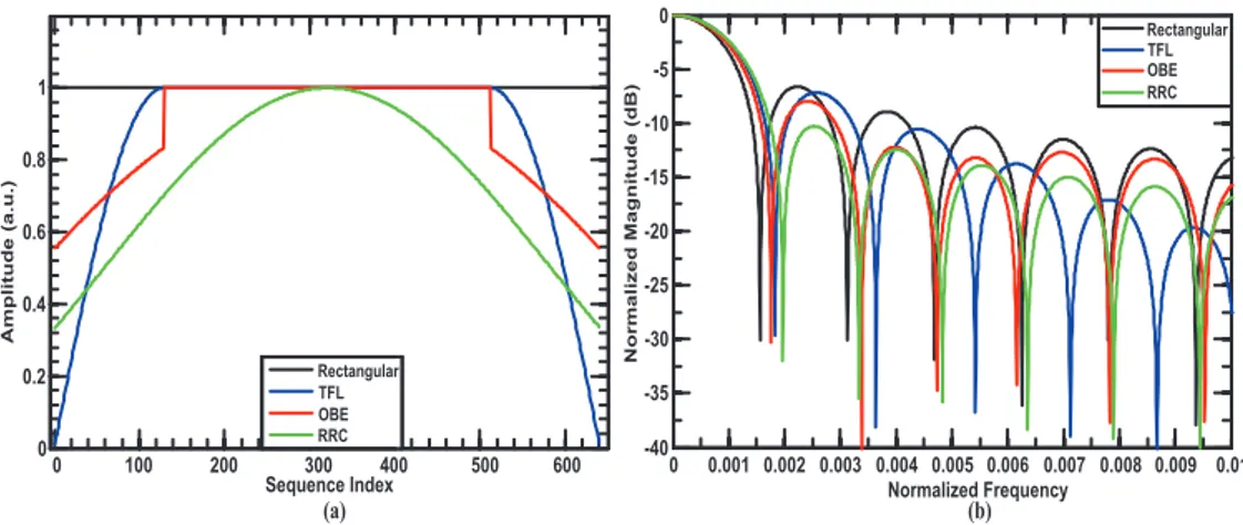
1:m p , , , , (8)0 100 200 300 400 500 600 Sequence Index Rectangular TFL OBE RRC 0 0.2 0.4 0.6 0.8 1 Amplitu de ( a .u .) Rectangular TFL OBE RRC 0 0.001 0.002 0.003 0.004 0.005 0.006 0.007 0.008 0.009 0.01 Normalized Frequency -40 -35 -30 -25 -20 -15 -10 -5 0 Norma lized Magn itude ( dB) (a) (b)
Fig. 1. Rectangular (black), TFL (blue), OBE (red) and RRC (green, α = 1) depiction of (a) impulse response and (b) frequency response. Rectangular has very high energy sidelobes. TFL pulse shape exhibits better localization in time and frequency than OBE. The difference between TFL and OBE is that TFL has higher sidelobe energy and quick energy decay; on the other hand OBE has lower sidelobe energy and slow energy decay. RRC shows good sidelobe energy, however it introduces high inter-symbol interference.
where sp is the useful part of the signal, ip is ICI term, and zp is the filtered noise. The useful
part of the signal should be maximized and the rest should be minimized in terms of mean power. First of all, in presence of a small residual CFO such that f < 1/M, with overlapped frequency domain signals, ICI mitigation suggests using frequency localized pulse shapes. On the other hand, the presence of additive white Gaussian noise justifies the use of orthogonal signaling (i.e. matched filtering) [14].
2.3 Perfect reconstruction filters
In this section, we will describe the two families of prototype filters that are used herein over time-frequency dispersive channel, namely rectangular pulse shape and short perfect reconstruction filters.
2.3.1 Biorthogonal rectangular pulse shapes
The cyclic prefix OFDM is known as a rectangular multicarrier modulation with worst frequency localization compared to any non-rectangular shaped OFDM signals [15, 16]. Therefore we choose rectangular pulse shape as a benchmark in our work. The CO-OFDM biorthogonal rectangular pulse shapes can be defined as:
RECT RECT 1, if 0 1, [ ] 0, otherwise, 1, if 1, [ ] 0, otherwise. k N k N - M k N k g g £ £ -ì = í î £ £ -ì = í î RECT[ ][ ][ ]k g = (9)
The first N – M coefficients of γRECT form the cyclic prefix in order to mitigate inter-symbol
interference introduced by time-dispersive channels. At the receiver side, the cyclic prefix is removed byggRECTRECT. The time and frequency response of the rectangular pulse shape is shown
in Figs. 1(a) and 1(b), respectively.
2.3.2 Orthogonal perfect reconstruction filters
The prototype filters described in [17] are derived from two optimization criteria: TFL and OBE. Using ∆ = N – M, closed-form expressions are given for both filters:
TFL (2 1) sin if 0 1, 4 1 if 1, [ ] (2( ) 1) sin if 1, 4 0 otherwise. k k k M k k M k N p g p ì æ + ö £ £ D -ç ÷ ï è D ø ï ï D £ £ -= í D - + æ ö ï ç ÷ £ £ -ï è D ø ï î (10) OBE (2 1) cos if 0 1, 2 1 if 1, [ ] (2 1) cos if 1, 2 0 otherwise. k a b k k M k k a b M k N g ì æ + + ö £ £ D -ç ÷ ï è D ø ï ï D £ £ -= í + æ ö ï + £ £ -ç ÷ ï è D ø ï î æ 1)ö ì (2(2(2(2 + ç ÷ ç 1)÷ æ 1)ö ç ÷ ç ÷ ì + a b a b a b a b a b a b a b a b è 2 ø ç ÷ 2 a b a b a b D ç ÷ ç ÷ ì (2(2(2(2 + a b ç ÷ ça b(2 ÷ æ (2 ö a b ì (2(2(2(2 + a b ç ÷ 2 a b ç ÷ ç ÷ æ (2(2(2 1)ö ç ÷ ç 1)÷ æ 1)ö ç ÷ ç ÷ æ ö a b a b a b a b a b a b a b è 2 ø ç ÷ 2 a b a b a b D ç ÷ ç ÷ æ (2(2 ö a b ç ÷ ça b(2 ÷ æ (2(2(2 ö a b ç ÷ 2 a b ç ÷ ç ÷ (11)
whereaaandbbare two constants given in [17] and depends on the ratio of M / ∆. The time-frequency analysis of the prototype pulse shapes are shown in Fig. 1, and plotted against rectangular pulse as a reference. From Fig. 1, TFL pulse shape exhibits better localization in time and frequency than OBE. In principal, both OBE and TFL are short length, perfect reconstruction (orthogonal) and have symmetric impulse response. The difference between these pulse shapes is that TFL has higher sidelobe power (lower than rectangular pulse shape) and quick power decay; on the other hand OBE has lower sidelobe power and slow power decay.
Since RRC pulse shape is investigated in this paper, OBE filter may be directly compared with RRC because they share the same optimization criterion. But, it is important to understand that the RRC pulse shape is a continuous time function, hence it has to be truncated in order to fit an N coefficients impulse response. Such a truncation prevents the perfect reconstruction and yield inter-symbol interference [18]. A comparison between TFL and RRC is not equitable because they are not optimized from the same criterion, where the former is optimized jointly in time and frequency resulting in minimization of second order moment with the constraint of N non-zero coefficients. The RRC pulse shape is shown in Fig. 1.
3. System overview
In order to evaluate the proposed method of non-rectangular perfect reconstruction pulse shapes, an end-to-end extensive simulation is carried out with 40 Gb/s quadrature phase shift
keying (QPSK) CO-OFDM system. The simulation system is constructed in MATLABTM, as
Fig. 2. System diagram of CO-OFDM with proposed pulse shaping and receiver dual filtering. Acronyms- S/P: serial-to-parallel, IFFT: inverse fast Fourier transform, CP: cyclic prefix, P/S: parallel-to-serial, TS: training symbol, DAC: digital-to-analogue converter, I: in-phase, Q: quadrature, OLO: optical local oscillator, ADC: analogue-to-digital converter, and FFT: fast Fourier transform.
As illustrated in Fig. 2, the serial data stream is converted to M = 512 parallel structured data prior to being mapped into gray coded QPSK modulation format. The first symbol is used for channel estimation, and 8 pilot symbols are placed in an interval of every 64 subcarriers for phase noise estimation. The QPSK data is then transformed into OFDM signal by performing IFFT of size 1024 operation, apart from the data subcarriers, the rest are padded with zeros for oversampling purpose. The duration of OFDM symbol is 40.1 ns. The OFDM signal is then appended by cyclic prefix at the rate of 25% to combat inter-symbol interference in long haul transmission. The extended OFDM symbol is then weighted with various pulse shapes, including rectangular, RRC with α of 0.1, 0.2, and 1, and the newly introduced TFL and OBE.
After the insertion of training symbol, the total transmitting symbols are 200. The electrical OFDM signal is optically modulated by IQ modulator, and transmitted over 400 km to 3600 km of single mode fiber (SMF), with loss coefficient: 0.2 dB/km, PMD coefficient: 0.1 ps/km1/2, CD coefficient: 16 ps/nm.km, and optical fiber nonlinearity coefficient: 1.22 W-1km-1. The optical fiber loss is compensated for every 80 km span by utilizing erbium-doped fiber amplifier (EDFA) with 16 dB gain and noise figure of 6 dB. The laser phase noise is modeled using the Wiener-Levy process, expressed as the variance σ2= 2πvt, where v is the combined laser linewidth and t is the time difference between two samples [19]. In this simulation, the amplified spontaneous emission (ASE) noise is added relative to each fiber span (80 km). At the receiver, the coherently detected signal is first frame synchronized and sampling frequency offset is not induced to purely study the mitigation of ICI due to residual CFO. To achieve optimum pulse shaping, a receiver dual filtering with the same shape as the transmitted is utilized for weighting. Rest of the receiver process is exactly the reverse of the transmitter except for the channel and phase noise estimations and compensations.
Table 1. Back-to-back Q-factor of CO-OFDM with various pulse shapes at 2 MHz residual CFO
Q-factor
Residual CFO Rectangular TFL OBE
RRC α = 0.1 RRC α = 0.2 RRC α = 1 2 MHz 17.4 dB 18.7 dB 19.6 dB 17.7 dB 17 dB 11.4 dB
4. Results and discussions
Table 1 and Fig. 3 present the back-to-back and optical launch power analysis, respectively, and the signal quality is quantified through the usage of Q-factor based on direct
0 2 4 6 8 10 12 14 Q-factor (dB) -14 -12 -10 -8 -6 -4 -2 0 Launch Power (dBm) No CFO Rectangular TFL OBE RRC α =0.1 RRC α =0.2 RRC α =1 Residual CFO = 2 MHz Combined Linewidth = 200 kHz Distance = 1600 km 7% FEC
Fig. 3. Optical launch power investigation with no CFO for rectangular pulse shape, and 2 MHz residual CFO across rectangular, TFL, OBE and RRC. α is 0.1, 0.2, and 1 for RRC pulse shape. The transmission distance is 1600 km.
error counting. The CO-OFDM transmission with rectangular pulse shape without any CFO is the benchmark, in other word it is the ideal received signal without ICI. Then, we deliberately introduce a residual CFO of 2 MHz and investigate the additional tolerance that can be provided by the proposed pulse shapes.
By utilizing a rectangular pulse shape and 2 MHz residual CFO, the Q-factor at the optical launch power of -5 dBm deteriorated from 12.9 dB to 8.9 dB, which clearly shown the criticalness of ICI and resulted in dropping below the 7% forward error correction (FEC) limit of 9.1 dB [20]. In the case of RRC pulse shape, the Q-factor at -6 dBm optical launch power for α of 0.1 and 0.2 is 9.3 dB and 9.1 dB, respectively, unveiling the optimum α as 0.1 and consequently agreeing with [9]. However, increasing the α to 1 introduces excessive inter-symbol interference, resulting in very worsen Q-factor, where at -8 dBm optical launch power, the Q-factor is 7.3 dB. One important aspect that needs to be addressed here is that the
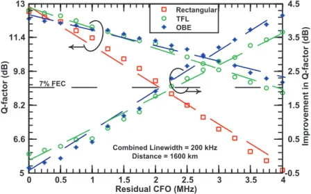
Rectangular TFL OBE -0.5 0.5 1.5 2.5 3.5 4.5 Improveme n t in Q-fa ctor ( dB ) Residual CFO (MHz) 0 0.5 1 1.5 2 2.5 3 3.5 4 5 6.6 8.2 9.8 11.4 13 Q-factor (dB) Combined Linewidth = 200 kHz Distance = 1600 km 7% FEC
Fig. 4. Impact of utilizing rectangular, TFL and OBE pulse shapes under varying residual CFOs at transmission distance of 1600 km.
optimum optical launch power point decreases with respect to the increasing α. This is due to the proportional increase of PAPR relative to the increase in α. Now we have shown the impact of applying RRC and confirmed the optimum α, although applying RRC resulted in Q-factor above the FEC limit, but the improvement is rather insignificant. Henceforth, the investigation on RRC will be dropped from rest of the paper.
It is clear from Fig. 3 that both TFL and OBE pulse shapes achieved the highest Q-factor under residual CFO of 2 MHz. At the optical launch power of -6 dBm, the Q-factor for TFL and OBE is 10.5 dB and 10.7 dB, respectively. The Q-factor improvement with respect to the rectangular pulse shape is 1.6 dB and 1.8 dB for TFL and OBE, respectively. It is clear that OBE provides better performance compared to TFL, although the difference is small. The superiority of OBE over TFL is due to the lower energy of sidelobes, as shown in Fig. 1(b). The overall improvement of both OBE and TFL pulse shapes over rectangular pulse shape is due to the improvement of frequency localization that results in lower energy sidelobes (see Fig. 1), hence under the influence of residual CFO, ICI occurs and lower energy sidelobes minimizes the impact. Similar to RRC, both TFL and OBE demonstrate a shift in the optimum optical launch power region due to the increase in PAPR. However, neither of these pulse shapes affect the peak power of OFDM signal. The pulse shaping function trims the symbol power over a period, as shown in Fig. 1, resulting in decreased average power compared to rectangular pulse shape. In other word, rectangular pulse shape retains the shape of the symbol over its period. Therefore, reduction in average power from pulse shaping results in increase of PAPR that shifts the optimum launch power region. The paper on PAPR evolution relative to pulse shaping by Roque et al can be referred for further information [21]. Since 2 MHz residual CFO was purely chosen under arbitrary condition, it is important to understand the credibility of the proposed pulse shapes. Therefore, we have conducted a detailed investigation of the performances of rectangular, TFL, and OBE pulse shapes over residual CFO(x), 0 £ x £ 4 MHz; for the transmission span of 1600 km, as shown in Fig. 4. At CFO of 0, all three pulse shapes exhibit almost similar performance. For residual CFO > 0.5 MHz, rectangular pulse shape performs worse than both TFL and OBE with continuous degradation in Q-factor with a very sharp slope, effectively demonstrating the rectangular pulse shape's sensitivity towards ICI. Since TFL pulse shape's side lobe is lower than rectangular pulse shape and higher than OBE, it provides an optimum compensation for ICI up to 1 MHz. However, OBE closely follows the trend of TFL up to 1 MHz. Beyond 1 MHz, due to OBE's much lower power based sidelobes, it exhibits better resilience towards increasing ICI compared to TFL and rectangular.
This investigation has revealed the possibilities of using TFL and OBE under selected conditions based on a CO-OFDM receiver performance. For an example, if the residual CFO is < 1 MHz and > 1 MHz, TFL and OBE can be employed, respectively. However, it is important to note that in a real field deployed system, over a span of time, the residual CFO will increase, although not indefinitely. Therefore, it is advisable to utilize OBE as it performs similar to rectangular and TFL pulse shapes for residual CFOs of < 0.5 MHz and < 1 MHz, respectively, and demonstrates exemplary performance for residual CFO beyond 1 MHz. The limit of CFO for OBE is approximately 4 MHz for 1600 km at the specified FEC limit. Beyond this limit, the transmission distance has to be proportionally shortened, or more robust equalization schemes have to be utilized, and such optimization is beyond the scope of this paper.
Linewidth is a major factor that contributes to phase noise and as well as the quality of a specific laser. In order to determine if the quality of an optical LO at the receiver of CO-OFDM can be flexible in terms of quality, next phase of the investigation will be covering the impact of linewidth broadening on the proposed pulse shapes under the condition of no CFO. The rational for no CFO is to purely study the effect of phase noise. Figure 5 illustrates the performance of rectangular, TFL and OBE pulse shapes under no CFO, at 1600 km transmission and expanding combined laser linewidth that proportionally increases the phase
0 3 6 9 12 15 Q-factor (dB) Rectangular TFL OBE No Residual CFO Distance = 1600 km 0 100 200 300 400 500 600 700
Combined Laser Linewidth (kHz)
Fig. 5. Rectangular, TFL and OBE pulse shapes behavior under continuous broadening of combined linewidth with no residual CFO, and at transmission distance of 1600 km.
noise. It is clear that additional phase noise induced by higher linewidth lasers have very similar impact on all three pulse shapes under no CFO. Hence, it is clear that the proposed pulse shapes behaves closely to the rectangular pulse shape and can be employed for ideal receivers, although ideal receivers is highly unlikely to occur in a practical system. Since it is well known that physical hardware, both optical and electrical will always introduce offsets and distortions, Fig. 4 has already shown the usefulness of the proposed pulse shapes.
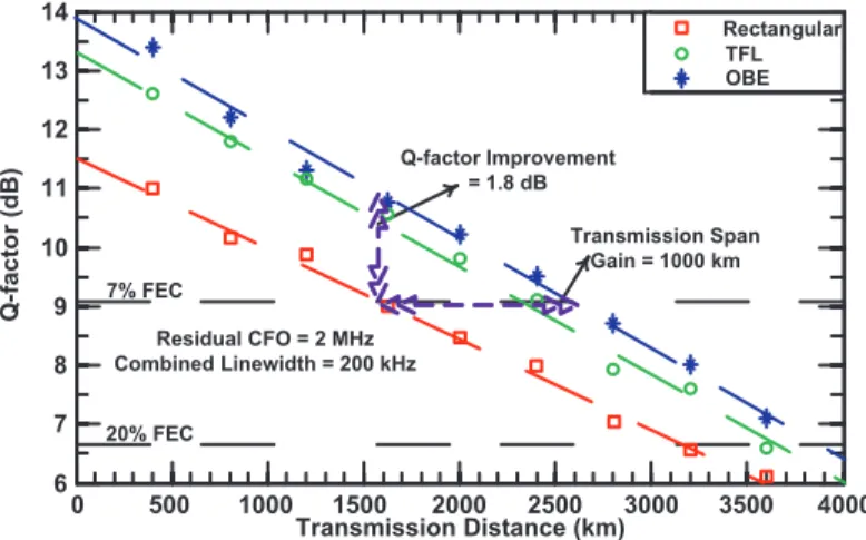
Finally, CO-OFDM mostly drawn great interest in the area of long-haul optical communication systems [22]. Therefore, in the first framework of these new pulse shapes, it is important to stress the proposed system and investigate its potential transmission ability. Figure 6 presents the transmission investigation for rectangular, TFL, and OBE pulse shapes from 400 km to 3600 km spans. The residual CFO is fixed at 2 MHz and a combined linewidth of 200 kHz. Taking 7% FEC as the first benchmark, rectangular pulse shape is capable of achieving this reference point for slightly less than 1600 km transmission. However, TFL and OBE pulse shapes achieved Q-factor improvements of 1.6 and 1.8 dB, respectively at the same transmission point. In the case of TFL and OBE pulse shapes at 7% FEC point, the achievable distances are 2400 km and 2600 km, respectively. It is clear that by employing OBE pulse shape, the improvement of transmission span is 1000 km with respect
Rectangular TFL OBE 0 500 1000 1500 2000 2500 3000 3500 4000 Transmission Distance (km) 6 7 8 9 10 11 12 13 14 Q -factor (dB ) Residual CFO = 2 MHz Combined Linewidth = 200 kHz 7% FEC 20% FEC Q-factor Improvement = 1.8 dB Transmission Span Gain = 1000 km
Fig. 6. Transmission investigation of Rectangular, TFL and OBE pulse shapes with 2 MHz residual CFO.
to rectangular pulse shaped system, which effectively translates into a ~62% gain. Long haul system can also be designed by taking 20% soft decision (SD)-FEC as the benchmark that results in Q-factor of 6.75 dB [23]. In the case of 20% SD-FEC, rectangular pulse shape is still able to reach a 3100 km transmission distance. For TFL pulse shape, the 20% SD-FEC meets at the span of 3500 km and OBE effectively has not reached the threshold of 20% SD-FEC even up to 3600 km transmission, thus showing the credibility of the proposed pulse shapes.
7. Conclusion
A simple residual CFO compensation method was proposed herein, based on short non-rectangular perfect reconstruction pulse shapes for CO-OFDM. Employing both OBE and TFL pulse shapes will significantly reduce the receiver complexity compared to employing exhaustive algorithms. The investigation reveals that TFL performs better for residual CFO < 1 MHz and vice versa for OBE. However, employing OBE for CFO < 1 MHz does not introduce significant penalty, and since the optical LO for CO-OFDM will drift over time, OBE would be the ideal pulse shape in real-time condition. It is also shown in the paper that the proposed pulse shapes is independent of laser phase noise, which is not the case for conventional residual CFO compensating algorithms. Finally, by employing OBE, a transmission span of 3600 km could be achieved without hitting the 20% SD-FEC limit. Acknowledgments
This work was partly funded by the European Community's Seventh Framework Programme (FP7/2007-2013) under grant agreement (FOX-C, n° 318415), EPSRC (Grant EP/J017582/1-UNLOC), and Aston Institute of Photonic Technologies for supporting the publication fee.