HAL Id: tel-02059492
https://pastel.archives-ouvertes.fr/tel-02059492
Submitted on 6 Mar 2019HAL is a multi-disciplinary open access archive for the deposit and dissemination of sci-entific research documents, whether they are pub-lished or not. The documents may come from teaching and research institutions in France or abroad, or from public or private research centers.
L’archive ouverte pluridisciplinaire HAL, est destinée au dépôt et à la diffusion de documents scientifiques de niveau recherche, publiés ou non, émanant des établissements d’enseignement et de recherche français ou étrangers, des laboratoires publics ou privés.
Mechanical Behaviour of Ultra fine grain aluminium
alloy. Analysis and modelling of the enhanced role of
grain boundaries
Anchal Goyal
To cite this version:
Anchal Goyal. Mechanical Behaviour of Ultra fine grain aluminium alloy. Analysis and modelling of the enhanced role of grain boundaries. Mechanics of materials [physics.class-ph]. Université Paris-Saclay, 2018. English. �NNT : 2018SACLX091�. �tel-02059492�
NNT
:2018SA
CLX091
Comportement mécanique d’un
alliage d’aluminium à grains
ultrafins. Analyse et modélisation
du rôle exacerbé des joints de
grains.
Thèse de doctorat de l’Université Paris-Saclay préparée à l’Ecole Polytechnique Ecole doctorale n 579 Sciences mécaniques et énergétiques, matériaux et géosciences (SMEMAG) Spécialité de doctorat: Mécanique des matériaux
Thèse présentée et soutenue à Palaiseau, le 29th November 2018, par
A
NCHAL
G
OYAL
Composition du Jury :
Edgar Rauch
Directeur de Recherche, Université Grenoble Alpes
(SIMAP) Rapporteur
Xavier Sauvage
Directeur de Recherche, Université de Rouen (GPM) Rapporteur Ilchat Sabirov
Senior Researcher, IMDEA Materials Examinateur
Jean-Jacques Fundenberger
Maître de Conférences, Université de Lorraine (LEM3) Examinateur Eric Charkaluk
Directeur de Recherche, Ecole Polytechnique (LMS) President Véronique Doquet
Abstract (English) Mechanical behaviour of ultra-fine grain Al 5083 alloy: Analysis and modelling of the role of grain boundaries to overall plastic deformation. Ultrafine grained (UFG) alloys seem promising, based on their high tensile properties and the possibility of superplastic forming at relatively low temperature. However, their deformation mechanisms are not fully understood, and their performance in fatigue has not been thoroughly investigated. This work compares the viscoplastic behaviour, and the de- formation and damage mechanisms in tension and fatigue of a UFG Al-Mg alloy (600 nm mean grain size) obtained by severe plastic deformation (ECAP process) with that of its coarse-grained (CG) counter- part. The strain rate sensitivity (SRS) of both materials has been measured during creep, relaxation and tensile tests run at various strain rates and temperature. Microstructural refinement is shown to increase the SRS, which rises as the strain rate decreases, and controls the ductility. The UFG material becomes softer and more ductile than the CG material at high temperature. The temperature and strain rate domain for which the UFG alloy is stronger or softer has been determined.
Tensile tests run in a SEM, with DIC measurements of strain fields at meso/micro scales (using gold microgrids printed by electron beam lithography) and at sub-micron scale (using a superfine speckle obtained by film remodelling) have shown that grain boundary sliding is more and more active in both materials as the temperature rises and as the strain rate decreases. Grain boundary sliding is cooperative and occurs mostly at high-angle grain boundaries in the UFG alloy, where the strain field is more heterogeneous, and where very high strain levels (>100%) are often observed in localized bands. A 2D finite element model taking into account the viscoplastic behaviour inside the grains, and viscous sliding at the grain boundaries has been identified other the whole temperature range investigated. It captures well the observed behaviours and the much larger contribution of grain boundary sliding in the UFG alloy. It also provides the evolution of this contribution during strain hardening. Plastic strain-controlled push-pull tests and stress- controlled push-pull tests were run to investigate the cyclic behaviour and damage mechanisms of the two materials in low and high-cycle fatigue. The tests were followed by fractographic observations, statistical analysis of surface damage, as well as TEM observations of dislocations arrangements. Both materials exhibit cyclic hardening, although it is more modest in the UFG alloy, in which grain growth occurs at high amplitude. While isotropic hardening predominates in the CG alloy where the density of dislocation strongly increases during cyclic tests, kinematic hardening predominates in the UFG alloy, because of its limited capacity to store dislocations and its more heterogeneous plastic deformation. For a given plastic strain range, the UFG alloy has a shorter fatigue life than its CG counterpart, because of a much easier crack initiation, mostly from intermetallic particles. For a given stress range, it has a slightly higher life, due to a slower development of microcracks, which have a transgranular path in the largest grains, with some intergranular growth within the smallest grains.
Abstract (French) Comportement mécanique d’un alliage d’aluminium à grains ultrafins : Analyse et modélisation du rôle exacerbé des joints de grains. Les alliages à grains ultrafins semblent prometteurs, au vu de leur forte résistance en traction et de la possibilité d'une mise en forme superplastique à basse température. Toutefois, leurs mécanismes de déformation, qui comportent une part plus ou moins forte de glissement aux joints de grains restent mal connus, et leurs performances en fatigue ont été peu étudiées. Ce travail vise à comparer et analyser le comportement viscoplastique et les mécanismes de déformation et d'endommagement en traction et en fatigue d’un alliage d’aluminium-magnésium "classique" et à grains ultrafins (600nm en moyenne) obtenu par déformation plastique sévère, selon le procédé ECAP. Des essais de relaxation, fluage et traction à diverses vitesses et températures ont permis de mesurer les évolutions des sensibilités à la vitesse en fonction de ces deux paramètres et de montrer: 1) que le raffinement microstructural accroît sensiblement la sensibilité à la vitesse 2) que ce paramètre augmente avec la vitesse de déformation 3) qu'il contrôle la ductilité du matériau à grains ultrafins, qui s'accroît donc à faible vitesse 4) que cette ductilité devient supérieure à celle du matériau classique lorsque la température s'élève. Les domaines de vitesse et température dans lesquels le raffinement microstructural accroît ou diminue la résistance en traction ont été délimités.
Les mécanismes de déformation et d'endommagement des deux matériaux ont été étudiés au moyen d'essais de traction sous MEB accompagnés de mesures des champs de déformation par corrélation d'images à plusieurs échelles: méso et microscopique, grâce à des microgrilles d'or et sub-micrométrique, grâce à un mouchetis très fin obtenu par démouillage d'un film d'or. Le glissement aux joints est d'autant plus actif, dans les deux matériaux, que la température augmente et que la vitesse de déformation diminue. Dans l'alliage à grains ultrafins, il a un caractère coopératif et survient préférentiellement aux joints de forte désorientation. Les champs de déformation sont plus hétérogènes dans le matériau à grains ultrafins, où le taux de déformation dépasse 100% dans des bandes localisées.
Un modèle éléments finis 2D intégrant, outre la viscoplasticité au sein des grains, un glissement visqueux des joints, a été identifié dans toute la gamme de température explorée et rend assez bien compte du comportement viscoplastique des deux matériaux et de la contribution beaucoup plus forte du glissement aux joints dans l'alliage à grains ultrafins. Il permet également de préciser comment évolue cette contribution au cours de l'écrouissage.
Des essais de traction-compression à déformation plastique imposée ont permis d'étudier la plasticité cyclique et les mécanismes d'endommagement en fatigue oligocyclique et des essais à contrainte imposée, d'explorer la fatigue à grand nombre de cycles. Les essais ont été suivis d'observations des surfaces de rupture et d'une analyse statistique de l'endommagement en surface, ainsi que d'observations au MET des arrangements de dislocations. Les deux matériaux manifestent un durcissement cyclique, plus modeste dans
l'alliage à grains ultrafins, qui présente, à forte amplitude, une croissance de ses grains. L'écrouissage isotrope prédomine dans l'alliage classique, où la densité de dislocations augmente fortement avec la plasticité cyclique, alors que l'écrouissage cinématique prédomine dans l'alliage à grains ultrafins, en raison de sa moindre aptitude à stocker des dislocations et de la plus grande hétérogénéité de sa déformation plastique. A même amplitude plastique, ce dernier a une durée de vie plus faible, en raison d'un amorçage bien plus rapide des fissures, à partir de particules intermétalliques. A contrainte imposée, le matériau a grain ultrafins a une durée de vie légèrement supérieure, grâce à une propagation plus lente des microfissures, dont le trajet est transgranulaire dans les plus gros grains et intergranulaire dans les plus petits.
Contents
Introduction 4
1 Literature survey 9
1.1 Basic notions about grain refinement by ECAP . . . 9
1.2 General trends in the mechanical behaviour of UFG materials . . . 17
1.2.1 Tensile or compressive behaviour at room temperature . . . 17
1.2.2 Effect of temperature on the flow stress of UFG materials . . . . 22
1.3 Effect of microstructural refinement on plastic deformation mechanisms 28 1.3.1 Grain boundary sliding and its quantification methods . . . 28
1.3.2 Grain rotation . . . 34
1.3.3 Shear bands and strain distribution . . . 35
1.4 Introduction to Al 5083 alloy and previous work on its UFG form . . . 37
1.4.1 UFG Al 5083 and its tensile properties at RT . . . 39
1.4.2 Dynamic strain ageing . . . 40
1.4.3 Superplasticity . . . 42 1.4.4 Creep behaviour . . . 44 1.4.5 Fatigue behaviour . . . 46 1.5 Open questions . . . 48 2 Investigated Materials 60 2.1 Coarse-grained (CG) materials . . . 61
2.2 Grain refinement by ECAP . . . 67
2.3 Ultrafine-grained (UFG) materials . . . 72
3 Experimental investigation of the viscoplastic behaviour of CG and UFG Al5083 (Macroscopic aspect) 80 3.1 Tensile Tests . . . 80
3.1.1 Procedure . . . 80
3.1.2 Results at room temperature (RT) . . . 82
3.1.3 Results at high temperature (HT) . . . 92
3.2 Relaxation tests and SRS measurements . . . 99
3.2.1 Procedure . . . 99
3.2.2 Results . . . 102
3.3 Discussion . . . 113
3.3.1 GB-hardening and softening . . . 113
Chapter 0 CONTENTS
3.4 Summary . . . 119
Appendices 121 3.A Creep tests on CG Al5083 . . . 121
3.A.1 Procedure . . . 121
3.A.2 Results . . . 121
3.B Tensile tests for CG material . . . 129
4 Deformation, damage and fracture mechanisms 133 4.1 Experimental procedures . . . 133
4.1.1 Surface patterning for DIC . . . 133
4.1.2 Incremental tensile testing and image capture . . . 139
4.1.3 DIC computation . . . 140
4.2 Observations and Analysis . . . 141
4.2.1 At room temperature . . . 141
4.2.2 At high temperature . . . 172
4.3 Discussion . . . 210
4.3.1 Strain heterogeneities in relation with mechanical and microstruc-tural parameters . . . 210
4.3.2 Grain boundary sliding (GBS) . . . 213
4.3.3 Role of second phase particles fracture on the strain rate depen-dence of ductility . . . 216
4.3.4 Activation of non-octahedral slip . . . 217
4.4 Summary . . . 221
5 Modeling and simulation of the viscoplastic behaviour of CG and UFG Al 5083 224 5.1 Literature Review . . . 224
5.2 Aim and principle of the present model . . . 237
5.3 Detailed description of the model . . . 238
5.3.1 Constitutive model for the grain interior . . . 238
5.3.2 Constitutive model for the grain boundaries . . . 239
5.3.3 Mesh generation and boundary conditions . . . 240
5.3.4 Determination of a representative volume element (RVE) . . . . 244
5.3.5 Identification of the parameters . . . 248
5.4 Results & Discussion . . . 251
5.5 Summary . . . 264
6 Cyclic plasticity and fatigue mechanisms 268 6.1 Experimental procedures . . . 268
6.2 Observations and results . . . 273
6.2.1 Cyclic plasticity . . . 273
6.2.2 Fatigue lives . . . 281
6.2.3 Damage mechanisms . . . 282
6.3 Discussion . . . 289
Chapter 0 CONTENTS
Introduction
The ability of a metal to deform plastically depends of the ability of its dislocations to move. When their motions are hindered by microstructural obstacles, like solute atoms, dispersoids, precipitates, twin boundaries or grain boundaries (GBs), it increases the strength of the metal at the expense of its ductility, while unhindered motions render the material soft and ductile.
Several strategies can be employed to increase the strength of metals:
Alloying is a long known method, however the alloying elements are often quite ex-pensive and a change in chemical composition can alter some functional properties: it leads to a loss of electrical conductivity for Cu alloys, a loss of bio-compatibility for Ti alloys or a decrease in resistance to intergranular corrosion for Al alloys.
Strain hardening, which is also a long known method, is quite effective. However, a pre-strain induces some anisotropy and leads to a reduction in ductility. In addition it is less effective to treat components for high temperature applications, because of temperature-induced recovery.
Finally, grain refinement, which was probably the most intensively investigated strategy during the last two decades, increases the strength of metals at least at room temperature (RT) according to Hall & Petch equation:
= 0+
k p
d (1)
Here, is the tensile yield strength, d is the mean grain size and 0 and k are material
constants. The coefficient k is generally higher in planar slip materials in which larger dislocations pileups can form on the GBs. However this relationship was found invalid for grain size below 20 nm approximately (Figure 1).
INTRODUCTION
Figure 1: Yield strength as a function of the inverse square root of the grain size for copper [1] Metallic materials having grain size less that 1 µm can be divided into two categories: "nanocrystalline materials", with grain size less than 100 nm and "ultrafine-grain (UFG) materials", with grain size in the range of 100-1000 nm. While UFG materials fall in the range of validity of Hall-Petch relation, this is not always the case for nanocrystalline materials. In addition, the latter exhibit a low hardening capacity and poor ductility. That is why in a chapter of Techniques de l’Ingénieur devoted to these materials, D. François wrote in 2010: "On constate donc que du point de vue des propriétés mé-caniques, les matériaux nanostructurés ne présentent pas d’avantages marquants, au contraire. Se limiter aux matériaux à grains ultrafins (de l’ordre de la centaine de nanométres) est la solution qui semble s’imposer": which means that nanocrystalline materials are disappointing in terms of mechanical properties, and that UFG seem more promising. He added that UFG materials deserve sufficient research regarding the effect of strain rate and temperature on deformation mechanisms, fatigue, creep and fracture [2].
Materials with grain size less than 1 µm can be produced in two ways [3], [4]. First is the "bottom-up" approach, where polycrystalline metal is assembled from individual atoms using deposition techniques, or by compaction of ultrafine or nano-crystalline powder obtained by cryomilling. However, the quantity of nanocrystalline or UFG ma-terial produced that way is very small and sometimes with a poor ductility due to high impurity contents and some residual porosity.
INTRODUCTION The second strategy is a "top-down" approach where coarse-grained (CG) metal is processed by severe plastic deformation (SPD) to introduce a high dislocation density leading to grain refinement by dynamic recrystallisation [5]. It was considered one of the most effective grain refinement procedure by Zhu et al. [4] because the processed metals can be produced relatively in bulk and are free from contamination and porosity, if the stress triaxiality ratio is sufficiently low, or -even better- negative during SPD [6].
Among the various SPD processes that currently exist (Equal Channel Angular Pressing (ECAP) [7], High Pressure Torsion [8], Accumulative Roll Bonding [9], Con-strained Groove Pressing [10], Accumulative Back Extrusion [11], Tubular Channel Angular Pressing [12], etc), one of the most attractive is ECAP because of the rela-tively large volume of uniformly deformed -and thus ultrafine grained material- that it can provide. This process was thus chosen to produce the UFG Al-Mg alloy of this study.
In CG materials, the flow processes are mostly intragranular in nature, but for UFG, and even more so, for nanocrystalline materials, "grain boundary-mediated plas-ticity"(GBMP, described in more details in the next chapter) becomes more important and would be responsible for the breakdown of Hall-Petch equation below a given grain size in nanocrystalline materials (Figure 1). At RT, GB strengthening results in an ex-cellent yield stress for UFG materials, but at elevated temperature, GBs can slide, and eventually lead to softening.
While a lot of research was devoted to the analysis and prediction of GBMP-induced breakdown of Hall-Petch equation at RT, as the grain size is refined into the nanometer range, the temperature and strain rate-controlled transition from GB-induced reinforcement to GB-GB-induced softening of UFG materials has been much less investigated and modelled. However, this transition has to be understood, in order to provide a safe maximum temperature for structural applications of UFG materials. That is one of the objectives of this study, in the case of Al 5083 alloy.
Besides, literature on UFG materials insists on their tendency for strain localiza-tion, which limits their ductility, but until now, this conclusion was based mostly on post-fracture observations of surface roughness and shear bands, without any insight into the progression of localization during plastic flow and limited quantitative data due to the high spatial resolution needed for an accurate measurement of strain distribution in UFG materials. This study aims at providing such elements, thanks to in situ tensile tests and fine-scale measurements of strain fields by Digital Image Correlation (DIC).
Finally, since the resistance to fatigue is a key factor for the choice of structural materials, the effect of microstructural refinement on cyclic plasticity and fatigue resis-tance needs to be investigated and analysed in terms of damage mechanisms.
Structure of the thesis
Structure of the thesis
The structure of the manuscript is as follows:
Chapter 1 first presents a general literature survey regarding the deformation mecha-nisms and mechanical properties of UFG materials, and later, a more specific review on CG and UFG Al 5083.
Chapter 2 focusses on the microstructural characterisation of the CG and UFG ma-terials of the study.
Chapter 3 presents a comparative analysis of the viscoplastic behaviour of CG and UFG Al 5083 from room temperature to 200 C. The focus is mostly on the effect of temperature and strain rate on the macroscopic properties, depending on grain size. Chapter 4 analyses the deformation and damage mechanisms of the two materials during the tests described in previous chapter, and suggests possible explanations for the observed differences in the mechanical behaviour.
After a literature survey on the introduction of grain boundary sliding in constitutive models, chapter 5 presents an attempt to capture its contrasted effects in CG and UFG materials, through a phenomenological viscoplastic model, with sliding interfaces. Chapter 6 presents a compared experimental study of the cyclic behaviour and fa-tigue resistance of the two materials at room temperature.
Finally, a concluding chapter summarizes the results, lists questions that remain open and proposes some perspectives.
References
[1] B. Bhushan and F. A. Mohamed, “Mechanical Properties of Nanocrystalline Metals,” Encyclopedia of Nanotechnology, 2012.
[2] D. François, “Propriétés mécaniques des matériaux nanostructurés,” Techniques de l’Ingenieur, p. m4029, 2010.
[3] Y. Huang and T. G. Langdon, “Advances in ultrafine-grained materials,” Materi-als Today, vol. 16, pp. 85–93, 2013.
[4] Y. T. Zhu, T. C. Lowe, and T. G. Langdon, “Performance and applications of nanostructured materials produced by severe plastic deformation,” Scripta Ma-terialia, vol. 51, pp. 825–830, 2004.
[5] V. M. Segal, “Materials processing by simple shear,” Materials Science and Engineering: A, vol. 197, pp. 157–164, 1995.
[6] R. Lapovok, “Damage evolution under severe plastic deformation,” International Journal of Fracture, vol. 115, pp. 159–172, 2002.
[7] Y. Iwahashi, J. Wang, Z. Horita, M. Nemoto, and T. G. Langdon, “Principle of equal-channel angular pressing for the processing of ultra-fine grained materi-als,” Scripta Materialia, vol. 35, pp. 143–146, 1996.
[8] A. P. Zhilyaev and T. G. Langdon, “Using high-pressure torsion for metal pro-cessing: Fundamentals and applications,” Progress in Materials Science, vol. 53, pp. 893–979, 2008.
[9] N. Tsuji, Y. Saito, H. Utsunomiya, and S. Tanigawa, “Ultra-fine grained bulk steel produced by accumulative roll-bonding (ARB) process,” Scripta Materialia, vol. 40, pp. 795–800, 1999.
[10] D. H. Shin, J. J. Park, Y. S. Kim, and K. T. Park, “Constrained groove pressing and its application to grain refinement of aluminum,” Materials Science and Engineering A, vol. 328, pp. 98–103, 2002.
[11] S. Fatemi-Varzaneh and A. Zarei-Hanzaki, “Accumulative back extrusion (ABE) processing as a novel bulk deformation method,” Materials Science and Engi-neering: A, vol. 504, pp. 104–106, 2009.
[12] G. Faraji, M. M. Mashhadi, and H. S. Kim, “Tubular channel angular pressing (TCAP) as a novel severe plastic deformation method for cylindrical tubes,” Materials Letters, vol. 65, pp. 3009–3012, 2011.
Chapter 1
Literature survey
1.1 Basic notions about grain refinement by ECAP
Equal channel angular pressing (ECAP) developed in 1973 in the Soviet Union by Se-gal [1] is an extrusion method for accumulating high plastic strains. It is a highly effec-tive method with respect to grain size refinement, since the extrusion happens without any change in billet shape and thus the process can be repeated several times, so that a very high plastic strain can be accumulated, if the material is ductile enough. Ultra-fine grained (UFG) materials of grain size ranging from 100 to 1000 nm can be produced using this method. Historically, it started with processing of pure metals, (UFG Ti, for example, is used in dentistry) but due to the lack of thermo-mechanical stability of pure metals, this process was later extended to alloys. So far, ECAP has been successfully applied for Al alloys, Cu alloys, Ti alloys, Pb alloys, Mg alloys and a few steels.
In ECAP, a billet with a circular or rectangular cross-section is forced through a die
with intersecting channels of similar width, at a die channel angle and the outer
corner angle , as shown in figure 1.1 [2].
Chapter 1 1.1. BASIC NOTIONS ABOUT GRAIN REFINEMENT BY ECAP The billet gets sheared sharply on crossing the line of intersection between the 2 chan-nels. The Von Mises equivalent plastic strain after N passes is given by [3]:
"eq= N/ p 3 2cot ✓ + 2 ◆ + cosec ✓ + 2 ◆ (1.1) The equivalent strain obtained for =90 and =0 is ⇠1 per pass, but it varies signifi-cantly depending on the die angle, outer corner angle, and friction conditions.
The maximum length and the aspect ratio of the billets are constrained by the re-quired pressing load (which depends both on the sample length and its diameter); and the risk of buckling of the punch, whose cross-section is the same as that of the billet. The maximum pressure required to extrude the specimen through the channel can be calculated as [4]. P = ⌧0(1 + m) 2cot ✓ + 2 ◆ + + 4m⌧0 ✓ li+ lo a ◆ (1.2)
Here, ⌧0 and m are the shear strength of the sample and friction coefficient, li and lo
are the instant length of the specimen at entry and exit channels, and a is the width of the channel, nearly equal to the billet diameter or side length. The length to diameter (or side length) ratio is generally less than 10.
Unrefined zones (also called "dead zones") are observed at both ends of the ECAPed rod [5]–[7] and have to be removed to machine test samples, leading to a wastage of matter (Figure 1.2).
(a)
(b)
(c)
Figure 1.2: (a) Plastic flow during ECAP emphasized by engraved grids [6], (b) Computed effective strain contour after one ECAP pass [8], (c) ECAPed rods [9].
Chapter 1 1.1. BASIC NOTIONS ABOUT GRAIN REFINEMENT BY ECAP It can be minimised by the application of a back pressure during ECAP. An addi-tional advantage of back pressure is to raise the hydrostatic compression, leading to enhanced ductility of the material (see Figure 1.3) and preventing the formation of nano-cavities and surface cracks [10]. Back pressure can be applied, ideally, using a secondary actuator [11], or by a slight reduction in diameter of the exit channel [12], however the latter solution is only effective for the first ECAP pass, while the diameter of the extruded sample is still higher than that of the exit channel.
Figure 1.3: Equivalent strain at fracture versus stress triaxiality for Al2024-T351 [13]. The mean grain size generally decreases in a non-linear way with the number of ECAP passes and reaches a steady-state value after a few passes. Mohamed proposed a model to predict the minimum grain size as a function of material parameters, such as the hardness, melting temperature, and stacking fault energy [14]. Although, it was developed for ball milling, it has been successfully applied to other SPD processes. If all other factors remain constant, the minimum achievable grain size is proportional to the amount of alloying element as inversely proportional to the stacking fault energy (SFE) as shown in figure 1.4. For Al-4.6%Mg, this value was predicted to be 0.27 µm [15].
Chapter 1 1.1. BASIC NOTIONS ABOUT GRAIN REFINEMENT BY ECAP
Figure 1.4: Relationship between the normalised stacking fault energy and the normalised minimum grain size [15].
This relation between minimum mean grain size and SFE was proven false by Edalati et al. [16]. Moreover, he showed that the the dominant factor for extra grain refinement by alloying is the effect of atomic-size and modulus mismatch on the mobility of edge dislocations. Thus, the minimum grain size decreases with the increase in the amount of alloying elements.
The evolution of hardness and yield stress is also observed to be non-linear with a tendency to reach steady state values after 2-3 passes only (Figure 1.5).
Figure 1.5: Effect of the number of pressings on (a) Vickers hardness, and (b) tensile properties of 5083 Al alloy after ECAP using Route C [17].
However, even when the grain size and tensile properties reach steady-state values, the microstructure still continues to evolve, as shown by Chowdhury et al. for Al 6xxx
Chapter 1 1.1. BASIC NOTIONS ABOUT GRAIN REFINEMENT BY ECAP series alloy [18]. The fraction of high angle grain boundaries (HAGBs, with misorien-tations higher than 15 ) was found to reach its maximum after only 4 passes, but the grain orientation distribution continued its evolution towards a random texture until 8 passes (Figure 1.6).
Figure 1.6: Evolution of grain misorientation distribution with increasing number of ECAP passes for Al6082 alloy [18].
The maximum number of ECAP passes achievable without damage of the sample depends on the ductility of the material, and hence can be increased by increasing the processing temperature. However, since the SFE rises with temperature, the ef-ficiency of the process in terms of grain size reduction decreases, because of the enhanced dynamic recovery. Increasing temperature also slows down the formation of HAGBs [19]. A decrease in pressing speed may increase the ductility (as explained below for UFG materials) and thus allow more passes. It also has a positive influence on microstructure: an increased fraction of HAGBs [20], more equiaxed grains [21], and on the mechanical properties: reduced flow localisation [22].
It has been shown that the efficiency of ECAP process -i.e. microstructural refine-ment, fragmentation and redistribution of second phase particles- depends largely on the processing "route" [23]–[26]. Initially, there were four basic processing routes de-fined by the rotation scheme of the sample between successive passes, as shown in figure 1.7 [2], [27]. In this figure, as well as in the whole manuscript, the entrance and exit directions are denoted by y and z, respectively, while x corresponds to the width of the sample.
Chapter 1 1.1. BASIC NOTIONS ABOUT GRAIN REFINEMENT BY ECAP
In route A, the billet is re-inserted without any rotation. In route BA, it is rotated
alter-natively by ±90 degrees around its axis between each pass, while in BC, it is rotated
by 90 degrees, always in the same direction. In route C, it is rotated by 180 degrees.
Z
Y
Figure 1.7: Four processing routes in ECAP [27].
Figure 1.8 compares the orientation of the maximum shear stress plane in the ref-erence frame of the sample during consecutive passes, for each route. It appears that all routes, except route C (which corresponds to reversed loading) lead to non-proportional loading [5], with transient latent hardening when the activated slip systems change, at the beginning of each pass, followed by softening, when the "memory" of the previous pass fades away. This can lead to strain localization and fracture. Some researchers thus prefer route C with proportional loading [28].
Chapter 1 1.1. BASIC NOTIONS ABOUT GRAIN REFINEMENT BY ECAP
Figure 1.8: Maximum shear stress planes for each route [2].
However, route BC is recognised as the most effective in yielding equiaxed grains,
while very elongated grains are observed for Route BA, with route C as an
interme-diate case (Figure 1.9a) [24], [26], [29]. The evolution towards HAGBs is also the
fastest for route BC, followed by route C and route A, making route BC the most
pop-ular choice. The resulting texture and mechanical properties of an ECAPed material vary significantly with the chosen route, as illustrated by the work of Soliman et al on aluminum (Figure 1.9b, c).
Chapter 1 1.1. BASIC NOTIONS ABOUT GRAIN REFINEMENT BY ECAP
Route A Route Bc
(a)
(b)
(c)
Figure 1.9: (a) Colour coded map of grain size b) compared fraction of texture fibres and c) compared yield stress for CP Al after 4 passes [29].
In most cases, a drop in ductility is observed after ECAP, due to a high dislocation density which decreases the hardening capacity [5], [30]. Well chosen annealing treat-ments that do not change the UFG microstructure, but promote recovery are often performed after ECAP, to regain ductility, at the price of a slight drop in yield stress. The processing route has a great influence on the ductility, especially in alloys which contain second phase particles and precipitates that get fragmented and redistributed during ECAP, as shown in figure 1.10 for Al-Si alloy [23], [31].
Chapter 1 GENERAL TRENDS IN THE MECHANICAL BEHAVIOUR
Figure 1.10: Stress-strain curves for as-cast and ECAPed Al-Si alloy [23].
The structure of the grains and grain boundaries (GBs) after ECAP or any other SPD process is modified and out of equilibrium. HRTEM observations by Horita et al. [32] revealed wavy, corrugated and faceted GBs. Such a high energy state promotes GB motion, to reach a more stable state. Danilenko et al. measured by TEM grain rota-tions of several degrees during 120s in situ annealing at 200 C on SPD- processed UFG Al, which is a direct evidence of a relaxation phenomenon [33].
The grain size distribution after ECAP is often heterogeneous with a mixed grain-subgrain structure and a high dislocation density [34]. The distribution of solute atoms and vacancies in alloys is also affected by SPD. Clusters and segregations of Mg atoms was observed at GBs and triple junctions in an HPT processed Al-Mg alloy [35]. SPD-induced vacancies were observed to annihilate at GBs leading to a vacancy gra-dient in grains and a vacancy flux towards GBs.
Finally, the diffusivity of UFG material is enhanced, as compared to CG materials, due to an increase in point defects concentration and an increased surface of GBs that constitute fast diffusion circuits. The diffusivity increases with increasing fraction of HAGBs [36].
1.2 General trends in the mechanical behaviour of UFG
materials
1.2.1 Tensile or compressive behaviour at room temperature
High values of yield and ultimate tensile stress, modest strain hardening, and thus low uniform elongation and relatively low fracture strain are characteristic features of the tensile behaviour of UFG materials. This tendency for early necking is consistent with Considere’s criterion, according to which failure should occur when the hardening rate,Chapter 1 GENERAL TRENDS IN THE MECHANICAL BEHAVIOUR
✓(✏)
(✏) < 1, ✓ =
d
d✏ (1.3)
However, the room temperature (RT) ductility of UFG materials often increases sub-stantially as the strain rate decreases, as reported by Sabirov et al. (Figure 1.11a), or Ivanov & Naydenkin [20]. This dramatic effect is consistent with the strain rate de-pendence of the strain rate sensitivity (Figure 1.11b), considering Hart’s (Equation 1.4) criterion for necking in viscous materials.
Figure 1.11: True stress-strain curves for the ECAPed AA6082 alloy (a) at different strain rates [37], (b) SRS evolution with the strain rate [38].
Chapter 1 GENERAL TRENDS IN THE MECHANICAL BEHAVIOUR According to Hart [39], plastic instability is predicted by:
✓(")
(") < 1 m (1.4)
where the strain rate sensitivity (SRS), m is defined as:
m = d
d ˙" (1.5)
When m is positive, the domain of plastic stability increases and the higher SRS found at low strain rates can explain the rise in ductility.
In FCC metals, grain refinement down to the UFG and nano-crystalline regimes leads to an increase in strain rate sensitivity (SRS), illustrated by figure 1.12 for Cu and Ni, while the opposite trend appears in BCC metal [40]. For FCC UFG metals, this some-what mitigates the detrimental effect of a reduced strain hardening.
Figure 1.12: Variation of SRS, m vs. grain size, d for (a) Cu and (b) Ni [40].
Many reports of tension-compression asymmetry, in nanocrystalline and UFG mate-rials can be found in the literature [41]–[45] and models based on the pressure de-pendence of dislocations self energy [41] or on molecular dynamics [46]–[48] were proposed to explain it, while the introduction of the first invariant in the yield criterion was proposed to capture it in constitutive equations.
However, many reports are based on questionable experimental data (different sample geometries and experimental set-ups in tension and compression, absence of exten-someter so that the machine stiffness may bias the results, no lubrication in compres-sion, reproducibility not documented...) and are conflicting (some report a higher yield stress in compression [41], [42], [44] or in tension [45], [49] or no difference [43], sug-gesting that this might not be an intrinsic effect of a small grain size. For ECAPed copper, the flow stress anisotropy was clearly related by Haouaoui et al. [49] to the anisotropic pre-strain induced by ECAP and to the Bauschinger effect responsible for a tension-compression asymmetry which changes its sign, depending on the loading direction, relative to the extrusion axes (Figure 1.13).
Chapter 1 GENERAL TRENDS IN THE MECHANICAL BEHAVIOUR
Figure 1.13: Yield stress differential (S.D.) in tension and compression along different loading directions of ECAPed Cu [49].
Residual stresses, if any, may also play a role in the tension-compression asymme-try of ECAPed materials. The number of available measurements of these stresses is quite limited: Reyes-Ruiz et al. [50] used X-ray diffraction to measure it near the surface (Figure 1.14a-b) or along a radial section (Figure 1.14c-d) after a single ECAP pass on 6061-T6 Al alloy at RT. They emphasized the effect of friction against the die, that makes residual stresses at the surface different from those in the bulk.
Chapter 1 GENERAL TRENDS IN THE MECHANICAL BEHAVIOUR
Figure 1.14: Residual stress measurements (a),(b) at the surface and (c), (d) along a radial section after a single ECAP pass on 6061-T6 Al alloy at RT [50].
Lee et al. [51] used neutron diffraction to measure it along a radial section, from the bottom to the top of the billet, after a single pass at RT in copper (Figure 1.15). In both cases, significant but heterogeneous residual stresses were measured. Subsequent annealing treatments may reduce it, but to an unknown extent.
Figure 1.15: Residual stress distribution along a radial section after a single ECAP pass on Cu measured by neutron diffraction [51].
Chapter 1 GENERAL TRENDS IN THE MECHANICAL BEHAVIOUR
1.2.2 Effect of temperature on the flow stress of UFG materials
At low temperatures, GBs act as barriers for mobile dislocations leading to an increase of dislocation density inside the grains, which in turn leads to a high flow stress. With increasing temperature and decreasing strain rate, their efficiency decreases as they behave as sinks for lattice dislocations, reducing their density inside the grain, and themselves become able to glide. Both effects contribute to softening. A transition from GB-induced hardening to GB-induced softening was observed with decrease in strain rate and increase temperature in UFG copper by Li et al. [52] and in Al-1.5Mg alloy by Kapoor et al.[53], as shown in figure 1.16. The data points, on the top figure, represent the strain rate for which the flow stress of UFG alloy is the same as that of CG alloy at a given temperature and the bottom figure shows the corresponding flow stress. This softening effect is not a consequence of the lack of thermal stability in UFG microstructure, as observed from the post deformation TEM micrographs by Kapoor et al. [53].Figure 1.16: Transition from strengthening to softening of UFG compared with CG Al-1.5%Mg alloy [53].
Their data were consistent with one of the two conditions proposed by Li et al. for GB-induced softening: that the mean grain size becomes smaller than the expected (stress-dependent) sub-grain size, so that dislocations are able to reach the neighbour-ing grain boundaries without storage at intragranular obstacles. The second condition, according to Li et al., is that "temperature is high and strain rate low enough to al-low grain boundaries to act as effective sinks which would quickly annihilate intruding
Chapter 1 GENERAL TRENDS IN THE MECHANICAL BEHAVIOUR dislocations" [52]. They estimated the rate-dependent transition temperature (which depends on the diffusivity of the GBs) for copper, but, as it can be seen on figure 1.17, these predictions did not capture well the experimental data. To date a predictive model of this transition, quite important for engineering applications of UFG materials, seems to be missing.
Figure 1.17: Transition from strengthening to softening of UFG Cu [52].
Furthermore, even though many experimental studies on the high temperature plastic behaviour of UFG materials were run, the interpretation of macro-scale effects in terms of deformation and damage mechanisms are often rather speculative, because of the combined experimental difficulties related to 1) the required spatial resolution of obser-vation techniques and 2) high temperature. An effort to document these mechanisms at fine scale and high temperature is thus done in the present work.
Chapter 1 GENERAL TRENDS IN THE MECHANICAL BEHAVIOUR Cyclic plasticity and fatigue of UFG materials
In pure UFG metals, cyclic softening is generally observed, above a certain amplitude, during plastic strain controlled fatigue tests, due to plasticity-induced grain growth (Fig-ure 1.18) [54].
ε
cum= 3.3
Figure 1.18: Evolution of the stress range in UFG Copper during strain-controlled fatigue tests and evidence of plasticity-induced grain growth [54].
Even without grain growth, which is the case for most of the UFG alloys and some pure UFG metals, like Ti, cyclic hardening is generally limited, which reflects a poor dislo-cation storage capacity and the absence of dislodislo-cation structures formation in UFG materials.
Due to the high yield strength of UFG and NC materials, an increase in fatigue lives is expected for stress-controlled, high cycle fatigue (HCF) tests. However, since CG materials are more ductile than their UFG and NC counterparts, common wisdom pre-dicts a reduction in low cycle fatigue (LCF) lives for UFG materials. These trends are reflected by the expected strain-life diagram plotted by Mughrabi and Höppel [55], pre-sented in figure 1.19.
Chapter 1 GENERAL TRENDS IN THE MECHANICAL BEHAVIOUR
Figure 1.19: Expected trend for the fatigue lives of strong UFG and more ductile CG materi-als [55].
LCF and HCF lives were compared for different CG and UFG materials by Mughrabi and Höppel (Figures 1.20 and 1.21). Although the S-N curve of UFG materials lies above that of CG material in LCF regime, there is actually no gain in life at equal plastic strain range (Figure 1.20b) and in some cases, a reduction in the resistance to LCF can be observed (Figure 1.21). A substantial gain in LCF and HCF lives was however observed by Cavaliere [56] and Estrin [57] in pure UFG metals (Ti, Al, Cu and Ni) for stress-controlled tests.
Figure 1.20: Wöhler (S-N) curve (left) and Coffin-Mason curve (right) for various CG and UFG materials [55].
Chapter 1 GENERAL TRENDS IN THE MECHANICAL BEHAVIOUR
Figure 1.21: Total-strain fatigue life diagram of CG and UFG Al, showing the crossing of the curves [55].
In high and very-high cycle fatigue, the largest grains and the largest defects (e.g. inclusions or pores) are more important than the average grain size, so that crack initi-ation and incipient growth are determined by heterogeneities in the microstructure and the "statistics of extremes".
In UFG pure metals, a higher near-threshold crack growth rate and a lower thresh-old K for crack growth values were observed, as compared to their CG counterpart, as shown in figure 1.22 [56]. Similar observation was made by Neindorf et al. for UFG steels [58].
Chapter 1 GENERAL TRENDS IN THE MECHANICAL BEHAVIOUR
μm
Figure 1.22: Mode I crack growth kinetics in various CG (denoted by "mc" as micro-crystalline) and UFG metals [56].
This decreased resistance to crack propagation in UFG material is usually blamed on smoother fracture paths and a reduction in roughness-induced crack closure with decrease in grain size. On the other hand, according to Irwin’s model, the plastic zone
size at the crack tip, ry is inversely proportional to the square of the tensile yield stress,
Y: ry = 1 2⇡ ✓ KI Y ◆2 (1.6)
Here, KI is the stress intensity factor.
Since UFG materials have a higher yield stress, a reduction in plastic zone size and thus of plasticity-induced crack closure is also expected, which might at the contrary induce an acceleration in crack propagation.
GBs can be expected to slow down transgranular crack growth or even arrest trans-granular microcracks in HCF, as they do in CG metals (Figure 1.23), but might, at the contrary, accelerate intergranular crack growth. Furthermore, the efficiency of GBs in blocking the propagation of fatigue microcracks depends on the relative misorientation between neighbouring grains, and more specifically the tilt and twist angles between their slip planes [59]. Since ECAPed UFG materials usually have a strong texture, the probability of highly misoriented grains might be lower than in non textured materials, so that the barrier effect of GBs might be lower than expected. Thus, in UFG materials, the role of GBs in fatigue is not so clear, and deserves an investigation.
Chapter 1 EFFECT OF MICROSTRUCTURAL REFINEMENT ON PLASTIC...
Figure 1.23: Crack length as a function of the number of push-pull cycles in the HCF regime for CG 316L Steel [60].
1.3 Effect of microstructural refinement on plastic
de-formation mechanisms
Below sub-micron level (< 1 µm), a transition from dislocation mediated to grain bound-ary mediated plasticity (grain boundbound-ary sliding (GBS), grain boundbound-ary migration and grain rotation) is observed. A few elements about these phenomena are thus given below.
1.3.1 Grain boundary sliding and its quantification methods
Grain boundary sliding (GBS) is a thermally activated process, normally expected in polycrystalline metals, at temperatures above 0.4Tm ( where Tm is the melting tem-perature). It is responsible for superplasticity and was thoroughly investigated in the 60s and 70s [61]–[63]. The constitutive equation below was proposed to describe it:
˙"GBS = A ✓ Gb kT ◆ ✓ b d ◆p⇣ G ⌘n exp ✓ Q RT ◆ (1.7) Here, G is the shear modulus; d the mean grain size; b the Burger’s vector; Q an activation energy, and A, p and n the constants. A typical value of n = 2 was identi-fied for various metals, which corresponds to a SRS of 0.5 observed in most cases for superplasticity and is typically used as a representation of GBS [64]. An increas-ing contribution of GBS is predicted as the grain size decreases. GBS indeed seems to be quite active at RT in UFG metals, although direct and convincing observations at the appropriate scale are not numerous. Yang et al provided such evidence (Fig-ure 1.24 [65]).
Chapter 1 EFFECT OF MICROSTRUCTURAL REFINEMENT ON PLASTIC...
Figure 1.24: Direct evidence of GBS using SEM+EBSD after 17% strain in UFG Pd [65] Raj & Ashby [63] predicted that grain boundary roughness and the presence of second-phase particles along the boundaries would slow down GBS. Experimental obser-vations by Matsunaga et al. [66] or Soula et al. [67] suggest that special GBs (⌃3, ⌃5... ⌃< 29 according to the CSL nomenclature) tend to slide less than "random" GBs (⌃>29), which was attributed to the greater ability of lattice dislocations to dissociate into random GBs, producing a glissile component responsible for GBS (Figure 1.25).
Figure 1.25: Grain boundary structure dependency of GBS in pure Zn [66]
Various micromechanical models of GBS have been developed [61]–[63] and will be reviewed in chapter 5.
Different intercept methods and averaging techniques were provided by Bell, Lang-don & Gifkins [68]–[70] to estimate the contribution of GBS to overall deformation,
Chapter 1 EFFECT OF MICROSTRUCTURAL REFINEMENT ON PLASTIC... based on a simple geometrical representation. For a planar GB with a 3D orientation characterized by two angles ✓ and , the sliding displacement can be decomposed in three components u, v, w (Figure 1.26), including an out-of-plane component v (Fig-ures 1.26 and 1.27) related by
u = v
tan +
w
tan✓ (1.8)
Figure 1.26: Schematic representation of grain boundary sliding [68]
Figure 1.27: Out-of-plane component of GBS [71]
Bell et al. [68] proposed 3 ways to estimate the contribution of grain boundary sliding
to the overall strain = "GBS/"T, based on measurements of the average value of u,
v or w over a large number of grain boundaries intercepted by series of lines of total length l parallel to the tensile axis,
"GBS = 1 l l X 0 u = 1 l l X 0 ✓ v tan + w tan✓ ◆ = k xd x X 0 v (1.9)
where, k is an averaging factor, issued from a statistics of grain boundaries emergence angle on the surface. Note that the appropriate value of k (1.4 for annealed samples,
Chapter 1 EFFECT OF MICROSTRUCTURAL REFINEMENT ON PLASTIC... and 1.1 for polished sample, according to Bell & Langdon) is generally unknown (es-pecially after SPD), and this constitutes a major source of error, which most often is not even discussed in papers that use this technique.
Most researchers measure in-plane horizontal grid shifts, u to estimate the contri-bution of GBS. However, since it is difficult to measure a reliable value of u from the longitudinal lines, the most popular approach is to use a series of transverse lines, t (perpendicular to the tensile axis). Since a transverse line tends to intersect bound-aries that are parallel to stress axis whereas a longitudinal one more frequently cuts transverse boundaries, equation 1.9 cannot be used directly and is modified by Bell & Langdon as follows: "GBS = 1 t t X 0 u· tan(✓) (1.10)
Gifkins et al. [69] measured all 3 components on four different materials to validate the estimates of GBS contribution based on their measurement. Based on the inclination of sliding GBs relative to the tensile axis, they also concluded that GBS was controlled by the resolved shear stress on the grain boundary.
This technique became quite popular and many applications to CG materials were made, for example, by Koike et al. [64]) who performed scanning laser microscopy measurements of the out-of-plane displacements of FIB-engraved lines (Figure 1.28), or by Soula et al. [67], who used SEM measurements of in-plane GBS-induced shift of microgrids with a 5 µm pitch to estimate GBS in a Ni based superalloy after creep.
Figure 1.28: Measurement of offsets on FIB-engraved lines to derive the contribution of GB sliding by Bell & Langdon’s method in AZ31 Mg alloy at 523K [64]
However, these techniques become somewhat questionable (Equation 1.8 assumes a fixed orientation of the GB during deformation, which is no more correct in case of grain rotation, or just of large deformation with a substantial change in grain shape) and more difficult to use for UFG materials, because 1) the exact position of the GBs may be difficult to detect and 2) a high spatial resolution measurement technique is
Chapter 1 EFFECT OF MICROSTRUCTURAL REFINEMENT ON PLASTIC... needed, but over a statistically representative area.
Clarisse [71] applied this technique, using AFM measurements of ledges heights formed at the grain boundaries (revealed by thermal etching), in a very fine grained alumina (grain size 0.98 µm ) during high temperature compression tests.
Han and Mohamed also used AFM to measure out-of-plane GB displacements in UFG (cyromilled) Al5083 alloy in which the GBs had been revealed by ion etching before
tensile tests at 10 4 s 1 at 200 C (Figure 1.29). They reported a contribution of GBS
to total strain in the range of 17 and 30% [72]. Their observations seem statistically representative, as they observed 4 different area containing approximately 200 grains each.
(a)
(b)
Figure 1.29: 2-D AFM images and corresponding height profiles in the same area before and after deformation. The table shows the contribution of GBS measured in different areas in Al 5083 alloy [72].
Ivanov et al. used FIB sectioning to measure the vertical surface offsets produced by GBS in pure UFG Al produced by ECAP, as shown in figure 1.30 [73]. They re-ported a contribution of GBS to overall deformation as high as 70% in some areas, which decreased with increasing strain (Figure 1.31). This technique however has several limitations. First, it is a destructive method, hence the thin foil analysed at every strain increment was different and second, the analysed volume was quite lim-ited (8-10 measurements of vertical offsets at each step) so that it is difficult to get statistically meaningful quantitative information.
Chapter 1 EFFECT OF MICROSTRUCTURAL REFINEMENT ON PLASTIC...
Figure 1.30: Vertical offsets (steps) on grain boundaries produced by GBS on a FIB cross section in UFG Al after tension [73].
Figure 1.31: Estimated contribution of GBS to the overall deformation in the local area versus the strain in this area for UFG Al [73].
It is a popular concept, although not based on very reliable elements, apart from rela-tively large offsets of scratches compared to the mean grain size, that in UFG materi-als, a group of favourably oriented grains slide together as a unit until they get blocked by an unfavourably oriented grain, where sliding is accommodated by dislocation mo-tion [74].
A more direct experimental characterization and a more elaborate mechanical anal-ysis of GBS in UFG materials are still needed at this stage.
Chapter 1 EFFECT OF MICROSTRUCTURAL REFINEMENT ON PLASTIC...
1.3.2 Grain rotation
Grain rotation, different from the change in crystal orientation induced by large slip deformation, is a plastic deformation mode observed mostly in NC and to some extent in UFG materials. According to Bobylev et al. [75] the rotation is mediated by diffusion-assisted climb of grain boundary dislocations (Figure 1.32).
Figure 1.32: Shear and rotation deformation modes in NC material containing a mesoscopic sliding surface. (a) Enhanced GBS along the mesoscopic sliding surfaces stops at a grain whose geometry prevents such sliding. (b) Lattice dislocations are emitted from a triple junction into the grain. They transform into GB dislocations whose slow climb controls the rate of both dislocation emission from the triple junction and thereby GBS. (c) Shear deformation mode transforms into rotation deformation occurring in the grain. The rotation deformation involves slow climb of GB dislocations, and the climb rate controls the rate of GBS [75].
After grain rotation, the aligned GBs form "smooth mesoscale sliding surfaces" which enhance cooperative GBS over distances larger than one grain size.
Chapter 1 EFFECT OF MICROSTRUCTURAL REFINEMENT ON PLASTIC...
Figure 1.33: Schematic diagram explaining the cooperative GBS facilitated by grain rotation in NC Pd10Au alloy [76].
Quantification of grain rotation is even more complicated than the quantification of GBS for UFG/nano materials because of the high resolution required to measure small rotations. Izadi et al. [77], Noskova et al. [78], Milligan et al. [79] and Mompiou & Legros [80] performed in-situ tensile tests in a TEM to measure the changes in grain orientations in nanocrystalline or UFG Al or Fe thin films. Rotations by several degrees were reported within a few percent strain. According to Mompiou et al: " Grain growth and rotation are limited to areas where the stress is concentrated, and occur as a col-lective process, involving several neighbouring grains. These mechanisms are carried out by the nucleation and propagation of GB dislocations" [80].
Ivanisenko et al. took this method a step forward, using crystal plasticity to predict and later subtract from the measured rotation, crystallographic orientation changes re-lated to dislocation glide on UFG Pd specimens [76]. It was shown that the smallest grains have a pronounced tendency for non-crystallographic rotations.
1.3.3 Shear bands and strain distribution
The way plastic strain is distributed in the volume plays an essential role in the resis-tance to ductile fracture of a metal.
Sabirov et al., observed that, in Al 6082 UFG alloy, the rise in ductility when the strain rate decreases (Figure 1.11) correlates with profuse micro shear banding and signs of cooperative GBS. Based on measurements of shear-induced offsets of scratches at their intersection with the bands (relatively large compared with the mean grain size), they report that these short (< 20 µm) and relatively wide micro-bands, homo-geneously distributed on the surface, locally accommodate 12 to 20% plastic strain
without damage, at 1.1⇥10 5 s 1, but that their width and surface fraction drop with
increasing strain rate, leading to a detrimental transition towards a few macro-shear bands spanning over the whole gage width (Figure 1.34) [81].
Chapter 1 EFFECT OF MICROSTRUCTURAL REFINEMENT ON PLASTIC...
Figure 1.34: 3D AFM images of deformation relief for UFG Al6082 alloy tested at: (a) 1.1⇥10 5 s 1, (b) 10 4 s 1and (c) 10 3s 1 [81].
Note that the broadening of strain localization bands depends on the hardening expo-nent and on the SRS: the higher the SRS, the stronger the local increase in viscous stress following a local increase in strain rate, and the higher the hardening exponent, the stronger the local increase in flow stress following a local increase in strain. Both effects hinder further localization, and favour band broadening, this leading to more diffused bands.
Several researchers used high resolution digital image correlation (HR-DIC) during in-situ tensile tests in a SEM to visualise the effect of microstructural heterogeneity, which is inevitable after SPD, on the strain fields [82]–[84]. Strain localisation primar-ily occurred within large grains due to higher dislocation-mediated plasticity, and then extended across neighbouring grains though HAGBs or along the interfaces between large and small grains via GB-mediated plasticity.
Chapter 1 INTRODUCTION TO AL 5083 ALLOY AND PREVIOUS WORK...
Figure 1.35: (a) Optical micrograph and (b) corresponding in-plane strain field obtained from DIC in UFG (cryomilled) Al 5083 alloy [82].
Kammers et al. [85] even used DIC during high temperature in situ tensile tests in a SEM for a local estimate of the SRS, close to LAGBs, HAGBs or inside grains, based on measurements of the local increment in plastic strain after a change in strain rate. DIC will also be used in the present work to document plastic strain distribution, de-pending on the strain level, strain rate and temperature and to compare this distribution in CG and UFG materials. Furthermore, due to meso-scale microstructural hetero-geneities in ECAPed materials, it is important not to focus only on a small area con-taining a few grains, but also to monitor strain fields over several hundreds of microns. That is why two-scale DIC will be used here.
1.4 Introduction to Al 5083 alloy and previous work on
its UFG form
Al 5083 aluminium alloy contains 4-5% Magnesium and traces of other elements: Mn, Fe, Cr and Si. It is a non-heat treatable, but strain hardenable alloy, which derives its strength from solid solution strengthening by Mg addition. It is an important commer-cial Al-Mg alloy owing to its high strength to weight ratio, high corrosion resistance, especially in sea water. It is also amenable to superplastic forming above 500 C, for a mean grain size in the range of 2-10 µm and has been exploited commercially for long time by automobile, marine and defense industries. It has good low-temperature tensile and fatigue properties and thus is also widely used for cryogenic applications. Since it contains more than 3% Mg, it is supersaturated at RT (Figure 1.36). Thus,
some of the magnesium precipitates in the form of -phase (Mg2Al3) particles,
dis-tributed along the grain boundaries [86]. Secondary Mn and Fe rich coarse intermetal-lic particles and Al-Mn-Fe-Cr–type rod shaped nano-dispersoids can also be found in this material.
Chapter 1 INTRODUCTION TO AL 5083 ALLOY AND PREVIOUS WORK...
Figure 1.36: Phase diagram for Al-Mg binary system [86].
Figure 1.37, from Chen et al. shows that an annealing treatment of 30 min up to 200 C does not significantly alter the RT yield stress, UTS and ductility of the material, and neither does it change the precipitates size or distribution. This point is important for the present study in which tension or relaxation tests were run up to 200 C [86].
Chapter 1 INTRODUCTION TO AL 5083 ALLOY AND PREVIOUS WORK...
1.4.1 UFG Al 5083 and its tensile properties at RT
Several studies on UFG Al 5083 can be found in the literature. Many of those deal with UFG or bimodal alloys obtained by cryomilling, powder compaction + extrusion or rolling[82], [84], while others concern UFG alloys obtained by ECAP, generally per-formed between 150 and 200 C [5], [17], [87].
Figure 1.38a, from Dupuy et al. [88] shows the evolution of the tensile stress-strain curve of Al 5083 at RT with the number of ECAP passes following route Bc, at 150 C, while figure 1.38b, compares the tensile curves after 8 passes of route A, Ba, Bc or C.
(a) (b)
Figure 1.38: RT evolution of tensile stress-strain curves with (a) number of ECAP passes for route Bc and (b) different routes after 8 ECAP passes for Al 5083 [88].
The increase in yield stress due to grain refinement is quite substantial in Al-Mg alloys,
for which the Hall-Petch coefficient, ky ( y = 0 + kyd 1/2) ranges from 0.12 to 0.28
MPa/m1/2 as shown in table 1.1.
Alloy ky (MPa/m1/2) Reference
cryomilled Al5083 0.28 [89] ECAPed Al-1%Mg 0.13 [90] ECAPed Al-3%Mg 0.15 [90] ECAPed Al 5083 0.10-0.16 [91] CG Al-4%Mg 0.22 [92] CG Al-5%Mg 0.12 [93]
Table 1.1: Values of Hall-Petch coefficients for Al-Mg alloys
Dupuy et al. have shown that although the coarse intermetallic particles, initially present in CG Al 5083, get fragmented and redistributed during ECAP, it does not prevent cavity nucleation from clusters of fragmented particles during tension (Fig-ure 1.39b) [94]. The shape, size and spatial distribution of intermetallic particles can thus play an important role in determining the ductility of both CG and UFG Al alloys. However, many papers on UFG Al alloys thoroughly describe grain size, shape and texture, but do not even mention these particles, whose role is seldom discussed.
Chapter 1 INTRODUCTION TO AL 5083 ALLOY AND PREVIOUS WORK...
(b) (a)
Figure 1.39: (a) Effect of number of extrusions (NE) on the mean surface of second phase particles, (b) SEM image of cavity nucleation at broken second phase particles [94].
1.4.2 Dynamic strain ageing
Like in all Al-Mg alloys, due to the dynamic interaction between solute Mg atoms and mobile dislocations, serrated flow is observed in Al 5083 alloy. This effect, also known as Portevin Le-Chatelier (PLC) effect is a manifestation of dynamic strain aging (DSA). Al-Mg alloys have often been chosen as model materials for the study of DSA, since the amplitude of the phenomenon can easily be changed by a change in Mg content, as illustrated by figure 1.40 [95].
Figure 1.40: Effects of strain and Mg content on the magnitude of the stress drops at RT in Al-Mg alloys [95].
Tell-tale signs of PLC effects are shear-mode failure instead of necking, negative strain rate sensitivity and serrated flow. The stress serrations are a result of repeated
Chapter 1 INTRODUCTION TO AL 5083 ALLOY AND PREVIOUS WORK... pinning-unpinning of mobile dislocations by Mg atoms if the temperature and strain rates allow the atoms to diffuse at a rate comparable to the dislocation glide velocity. PLC bands are generally classified, based on their frequency and the shape of the serrations on the stress-strain curve, into 3 types, type A: avalanche-like shearing pattern, with continuously propagating bands, type B: discontinuous hopping like be-haviour with hopping distance almost the same scale as the specimen thickness, and type C: strong and regular stress drops at relatively high frequency (Figure 1.41) [96], [97].
Figure 1.41: True stress-strain curves representing conventional PLC types [97]. PLC instabilities shift from one type to the other or disappear depending upon the ap-plied strain rate and temperature (Figure 1.42). At low strain rate and high temperature, the PLC effect disappears because mobile dislocations keep dragging solute atoms. The high strain rate and low temperature domain, where PLC effect also disappears, corresponds to friction of unpinned dislocations on the crystal lattice. And in-between those two regimes, type A, B or C bands can be observed.
Chapter 1 INTRODUCTION TO AL 5083 ALLOY AND PREVIOUS WORK...
Figure 1.42: Temperature and strain rate regimes of PLC effect in Al-Mg alloys [98]. A few research was done to study the effect of grain refinement down to UFG regime on DSA in AL-MG alloys. There is no consensus on the effect of grain refinement on PLC effect, however, a trend seems to emerge. The amplitude of stress serrations was reduced in UFG Al-Mg alloys with less than 3% Mg [99]–[101], while for Al-Mg alloys with more than 3% Mg elevated stress serrations were reported after ECAP [102]– [104]. The trend seems logical since Mg is dissolved completely below 3%, and there might not be enough solute Mg atoms to pin the increased dislocation density after ECAP. Kaneko et al. [105] have shown that SPD processing can produce supersat-urated Al-Mg solutions (up to 30% Mg without any precipitation). If ECAP fragments Mg-rich second phase particles and even dissolves some of it, the UFG alloy might be supersaturated in Mg, and contain enough solute atoms to interact with their high dislocation density, this leading to larger serrations than in their CG counterparts.
1.4.3 Superplasticity
CG Al 5083 alloy (with grain size⇠2-10 µm) exhibits superplasticity at low strain rate
(<10 3 s 1) and high temperature (>450 C) [106]–[108]. Elongations to failure as high
Chapter 1 INTRODUCTION TO AL 5083 ALLOY AND PREVIOUS WORK...
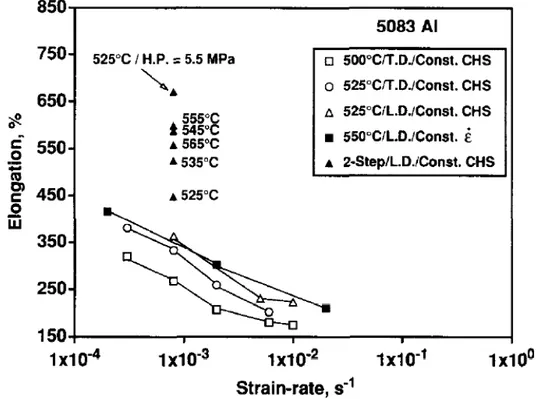
Figure 1.43: Maximum elongation to failure as a function of initial strain rate and temperature for CG (⇠9 µm) Al 5083 alloy (T.D. and L.D. denotes specimens cut with tensile axis parallel to transverse and longitudinal directions, respectively and CHS stands for constant cross-head speed) [107].
According to Chauhan et al., superplasticity can be achieved at higher strain rates in
UFG Al 5083. They obtained an elongation of about 350% at 0.1 s 1 and 523 K, as
shown on figure 1.44 [109].
Figure 1.44: Maximum elongation to failure as a function of initial strain rate at temperatures 523-648 K [109].
Chapter 1 INTRODUCTION TO AL 5083 ALLOY AND PREVIOUS WORK... for ECAPed Al5083 alloy. The tensile elongation to failure not only varied with aver-age grain size but also with the percentaver-age of HAGBs. Elongations of up to 300% were achieved at 548 K for UFG Al5083 (with 300 nm mean grain size), after 8 ECAP passes at 200 C (50% of HAGBs), while after 4 passes (similar grain size, but only 35% HAGBs) the maximum elongation was "only" 140%, as shown in figure 1.45.
Figure 1.45: Variation of elongation to failure as a function of initial strain rate at 548 K [110]. Most studies on the high temperature properties of UFG Al 5083 aimed at allowing superplastic forming at lower temperature and higher strain rate than in CG material, and were thus performed above 530 K. The number of studies of the viscoplastic behaviour of this material at lower temperatures is actually limited. Such temperatures might however be encountered in service and it is important, for example, to document and analyse the transition from GB-induced strengthening to GB-induced softening in Al 5083, as it was done for other alloys.
1.4.4 Creep behaviour
Outside the superplastic regime, the creep behaviour of CG Al-Mg alloys shows a typ-ical class I (Alloy type) solid solution behaviour with a stress exponent of 3, indicating solute-drag as a controlling mechanism, and a power-law breakdown at high stresses (Figure 1.46a) [111]. The activation energy of ⇠142 kJ/mol which is generally ob-served corresponds both to the activation energy of solute Mg diffusion in Al and self diffusion of Al in Al matrix.
The creep behaviour of Al-Mg alloys becomes more complicated below 0.5Tm [111], a regime where very limited data is available. Figure 1.46b shows the low temperature creep behaviour of Al-3%Mg [111]. The stress exponent and the activation energy for creep approach infinity. It is well accepted that in this region creep is controlled by
Chapter 1 INTRODUCTION TO AL 5083 ALLOY AND PREVIOUS WORK... the interaction of solute atmospheres with moving dislocations to such a level that an athermal type trend is achieved.
(a)
(b)
Figure 1.46: (a) Zener-Hollomon parameter as a function of modulus compensated stress for Al-Mg alloys. (b) Low temperature data of an Al-3%Mg alloy plotted with high temperature data from similar alloys [111].
The creep behaviour of UFG (ECAPed) Al 5083 alloy was analysed by Kim et al. in the temperature range of 498 to 548 K [112]. The value of stress exponent was ob-served to be 3.5 at low stresses and increased to 4.5 at high stress (Figure 1.47). Even though creep is controlled by solute-drag processes, the creep curve exhibited a class II (Metal type) creep behaviour. Activation energies of 72.6 and 96.1 kJ/mol were determined at low and high stresses, respectively. This indicates that at low stresses, creep deformation is controlled by dislocation glide while at high stresses, it is con-trolled by dislocation climb.
The existence of a thermally activated threshold stress was detected in various studies for both CG and UFG materials [109], [112]–[114]. However, it was only introduced as a fitting parameter to obtain a power-law relation for creep data. The physical basis of such a parameter is not clear. According to Chauhan et al. [109] and Kaibyshev et al. [113], the threshold stress originates from the interaction of dislocations with nano-dispersoids or other incoherent particles, while Kim et al. assume that the threshold stress is related to the initiation of glide at triple junctions, ledges, or particles at GBs. They use this reasoning to explain the lower threshold stresses in UFG materials which have more grain corners as well as particles per unit volume lying on GBs and thus more glide sources can be activated.
![Figure 1.10: Stress-strain curves for as-cast and ECAPed Al-Si alloy [23].](https://thumb-eu.123doks.com/thumbv2/123doknet/2640440.59524/22.892.247.647.147.390/figure-stress-strain-curves-cast-ecaped-al-alloy.webp)
![Figure 1.11: True stress-strain curves for the ECAPed AA6082 alloy (a) at different strain rates [37], (b) SRS evolution with the strain rate [38].](https://thumb-eu.123doks.com/thumbv2/123doknet/2640440.59524/23.892.205.686.373.1001/figure-stress-strain-curves-ecaped-different-strain-evolution.webp)
![Figure 1.16: Transition from strengthening to softening of UFG compared with CG Al-1.5%Mg alloy [53].](https://thumb-eu.123doks.com/thumbv2/123doknet/2640440.59524/27.892.276.614.473.921/figure-transition-strengthening-softening-ufg-compared-cg-alloy.webp)
![Figure 1.21: Total-strain fatigue life diagram of CG and UFG Al, showing the crossing of the curves [55].](https://thumb-eu.123doks.com/thumbv2/123doknet/2640440.59524/31.892.214.680.147.517/figure-total-strain-fatigue-diagram-showing-crossing-curves.webp)
![Figure 1.23: Crack length as a function of the number of push-pull cycles in the HCF regime for CG 316L Steel [60].](https://thumb-eu.123doks.com/thumbv2/123doknet/2640440.59524/33.892.217.675.145.380/figure-crack-length-function-number-cycles-regime-steel.webp)
![Figure 1.24: Direct evidence of GBS using SEM+EBSD after 17% strain in UFG Pd [65] Raj & Ashby [63] predicted that grain boundary roughness and the presence of second-phase particles along the boundaries would slow down GBS](https://thumb-eu.123doks.com/thumbv2/123doknet/2640440.59524/34.892.276.617.132.485/figure-evidence-predicted-boundary-roughness-presence-particles-boundaries.webp)

![Figure 1.34: 3D AFM images of deformation relief for UFG Al6082 alloy tested at: (a) 1.1⇥10 5 s 1 , (b) 10 4 s 1 and (c) 10 3 s 1 [81].](https://thumb-eu.123doks.com/thumbv2/123doknet/2640440.59524/41.892.244.644.134.644/figure-afm-images-deformation-relief-ufg-alloy-tested.webp)
![Figure 1.49: Evolutions of tensile and compressive peak stresses during plastic-strain con- con-trolled push-pull tests in CG (H131) and UFG (cryomilled-CM) Al 5083 alloys [116].](https://thumb-eu.123doks.com/thumbv2/123doknet/2640440.59524/52.892.244.648.675.982/figure-evolutions-tensile-compressive-stresses-plastic-trolled-cryomilled.webp)
