wrn UNivEKsrrEDE
lari S H F R R R O Q K F
Faculte de genie
Departement de genie chimique
Synthese de nanoparticules de carbure de fer dans un
reacteur a plasma inductif
Synthesis of Iron Carbide Nanoparticles in an Induction
Plasma Reactor
Memoire de maitrise es sciences appliquees
Speciality : genie chimique
Composition du jury
Francois Gitzhofer
Nicolas Abatzoglou
Ajay K. Dalai
Denis Gravelle
Roham Eslahpazir Esfandabadi
1*1
Library and Archives Canada Published Heritage Branch 395 Wellington Street Ottawa ON K1A0N4 Canada Bibliotheque et Archives Canada Direction du Patrimoine de I'edition 395, rue Wellington Ottawa ON K1A0N4 CanadaYour file Votre reference ISBN: 978-0-494-49497-4 Our file Notre reference ISBN: 978-0-494-49497-4
NOTICE:
The author has granted a non-exclusive license allowing Library and Archives Canada to reproduce, publish, archive, preserve, conserve, communicate to the public by
telecommunication or on the Internet, loan, distribute and sell theses
worldwide, for commercial or non-commercial purposes, in microform, paper, electronic and/or any other formats.
AVIS:
L'auteur a accorde une licence non exclusive permettant a la Bibliotheque et Archives Canada de reproduire, publier, archiver,
sauvegarder, conserver, transmettre au public par telecommunication ou par Plntemet, prefer, distribuer et vendre des theses partout dans le monde, a des fins commerciales ou autres, sur support microforme, papier, electronique et/ou autres formats.
The author retains copyright ownership and moral rights in this thesis. Neither the thesis nor substantial extracts from it may be printed or otherwise reproduced without the author's permission.
L'auteur conserve la propriete du droit d'auteur et des droits moraux qui protege cette these. Ni la these ni des extraits substantiels de celle-ci ne doivent etre imprimes ou autrement reproduits sans son autorisation.
In compliance with the Canadian Privacy Act some supporting forms may have been removed from this thesis.
Conformement a la loi canadienne sur la protection de la vie privee, quelques formulaires secondaires ont ete enleves de cette these.
While these forms may be included in the document page count,
their removal does not represent any loss of content from the thesis.
Bien que ces formulaires
aient inclus dans la pagination, il n'y aura aucun contenu manquant.
Resume
Dans cette etude, les nanoparticles de carbure de fer ont ete synthetisees dans un reacteur a plasma inductif. Dans ce travail nous nous sommes concentres sur les applications du carbure de fer comme catalyseur de la reaction Fischer-Tropsch. II y a beaucoup d'applications pour le carbure de fer en recherche et dans l'industrie, comme par exemple dans les ferrofluides, l'enregistrement magnetique et les biocapteurs.
Deux differentes methodes d'injection ont ete utilisees dans ce projet. L'injection de suspension avec l'avantage d'injecter des precurseurs heterogenes, et l'injection de solide pour introduire les precurseurs avec tout ratio molaire desire.
L'influence de differents facteurs a ete etudiee (puissance, debit d'injection, position de la sonde, taille de particules et ratio molaire des reactifs) sur la composition chimique ainsi que la morphologie des particules produites. Differentes methodes de caracterisation comme, la diffraction des rayons X (DRX), la microscopie electronique a balayage (MEB), la microscopie electronique a transmission (MET), l'analyse thermogravimetrique, et l'analyse de la surface specifique par methode BET ont ete utilisees.
Les resultats de DRX ont montre que les particules produites contiennent environs 50% massique de carbure de fer et que les autres composants produits sont l'austenite, le graphite et le fer pur. Les images de MEB et MET ont revele que les particules nanometriques avec des diametres entre 10 et 50 nm ont ete produites a cote de plus grosses particules de diametre entre 1 et 5 urn. Les images de MET en haute resolution ont montre que les particules nanometriques ont une structure «noyau-coquille» et qu'elles sont enrobees avec une couche de carbone amorphe et graphitique.
Une nouvelle technique de collecte de nanopoudre produite a aussi ete developpee afin de collecter des poudres dans un liquide inerte. Le but de cette methode est de minimiser la dispersion des nanoparticules dans l'air et de les proteger contre l'oxydation instantanee.
Mots-cles: plasma inductif, nanoparticules, carbure de fer, injection de suspension, reaction Fischer-Tropsch, catalyseur
Abstract
In this study nanometric iron carbide particles were produced by using an induction thermal plasma reactor. There are several applications for iron carbide particles in research and industry, such as in ferrofluids, magnetic recording and biosensors. We are focused in this project on its application as catalyst for Fischer-Tropsch reaction.
Two different injection methods were used in this study. Suspension injection was used because of its capability to inject heterogeneous precursors, and solid injection was used to inject reactants with any desired molar ratio.
The effect of several process parameters was investigated (plate power, injection rate, probe position, particle size and reactant ratio) and composition and morphology of produced powder were characterized using several characterization techniques including X-ray Diffraction (XRD), Scanning Electron Microscopy (SEM), Transmission Electron Microscopy (TEM), Thermogravimetric Analysis (TGA), and specific surface area measurement using BET method.
XRD results showed that the produced powder has about 50% of iron carbide alongside other phases such as pure iron, austenite and graphite. SEM and TEM images revealed that nanometric particles with a diameter between 10-50 nm were produced alongside larger particles with diameter between 1 to 3 p,m. High resolution TEM images showed that the produced nanometric particles have a core-shell structure and that they are embedded in an amorphous carbon.
A new method has also been developed to collect the produced nanopowder in a liquid in order to minimize nanoparticle dispersion into the air, and protect pyrophoric nanoparticles from air exposure.
Keywords: Induction thermal plasma, nanoparticle, iron carbide, suspension injection, Fischer-Tropsch reaction, catalyst
Acknowledgment
My first thanks go to my supervisors Prof. Francois Gitzhofer and Prof. Nicolas Abatzoglou who helped me during realization of this project. Without their scientific advises, patience and encouragement this project could have never been accomplished.
All members of Plasma Technologies Research Centre (CREPE) especially Mr. Francis Barrette with his technical support have helped me in this project. Contributions of all my group mates in Groupe de Recherche en Energie et Environnement (GREEN) with their supports and advises are gratefully acknowledged.
I would like to thank the Natural Science and Engineering Research Council (NSERC) of Canada, Natural resources of Canada, and Enerkem Company for their financial supports.
Finally and specially, I want to thank my wife, Nafiseh, for her encouragement and patience which was a source of love and positive energy for me.
Table of Content
1. INTRODUCTION 1 1.1. Overview 1 1.2. Iron carbide Applications 2
1.2.1. Miscellaneous applications 2 1.2.2. Fischer-Tropsch reaction 3 1.3. Nanometric iron carbide synthesis techniques 5
1.4. Problem description and thesis objectives 6
1.5. Structure of the thesis 7 2. LITERATURE REVIEW 9
2.1. Overview.. 9 2.2. Chemical vapor condensation (CVC) 9
2.3. Chemical vapor deposition (CVD) 10
2.4. Laser pyrolysis 12 2.5. Arc discharge 13 2.6. Thermal plasma 17
2.6.1. The plasma state 17 2.6.2. Thermodynamic and transport properties 18
2.6.3. Generation of radio frequency (RF) plasma 23 2.6.4. Nanoparticles synthesis by R.F plasma 24
3. EXPERIMENTAL METHODS 27 3.1. Experimental set up 27 3.2. Injection techniques 31 3.3. Wet collection method 33 3.4. Characterization techniques 36 3.5. Operating conditions 39 3.6. Experimental design 41 4. RESULTS AND DISCUSSIONS 42
4.1. Overview and objectives 42 4.2. Suspension Injection: Preliminary results 42
4.2.1. Objectives 42 4.2.2. Thermodynamic analysis 42
4.2.3. Preparation 45 4.2.4. Oxygen containing precursors 46
4.2.5. Hydrocarbon precursor 51
4.2.6. Discussions. 53 4.3. Suspension injection: statistical analysis 55
4.3.1. Objectives , 55
4.3.2. Determination of 23 design levels 55
4.3.3. Characterization 57 4.3.4. Statistical analysis... 64
4.3.5. Discussions 66 4.4. Solid injection technique 68
4.4.1. Objectives 68 4.4.2. Operational conditions and results 69
4.4.3. Characterization 72 4.4.4. Discussions 77
CONCLUSION 80 References 83
List of Figures
Figure 2.1 Laser pyrolysis system for nanoparticle production 12
Figure 2.2 Classic arc discharge reactor 14 Figure 2.3 X-ray diffraction spectra of (a) Fe(C), (b) Co(C) and (c) Fe-Co(C) nanocapsules 15
Figure 2.4 HRTEM images showing the shell-core structure of Fe(C) 16
Figure 2.5 Encapsulated iron nanoparticles 17 Figure 2.6 Typical range of electron temperature and electron density for thermal and cold
plasma 18 Figure 2.7 Composition of (a) argon, (b) nitrogen, plasma as a function of temperature 19
Figure 2.8 Specific enthalpy of some monatomic and molecular gases as a function of
temperature 20 Figure 2.9 Thermal conductivity of E^/Ar mixture as a function of temperature 21
Figure 2.10 Axial profiles of the (a) velocity, (b) temperature and (c) injected gas
concentration 22 Figure 2.11 Axial profiles of the (a) viscosity, (b) thermal conductivity and (c) mass
diffusivity 23 Figure 2.12 Schematic view of dual-RF torch 25
Figure 2.13 TEM images of Fe Si-C powder 26
Figure 3.1 Experimental set up 28
Figure 3.2 Plasma torch 29 Figure 3.3 Suspension injection probe 30
Figure 3.4 SEM images of initial iron particle 31 Figure 3.5 Two schematic view of liquid injection flange 33
Figure 3.6 Liquid film formation during wet collection 34 Figure 4.1 Thermodynamic equilibrium of the butanol/glycerol/iron system 43
Figure 4.2 Thermodynamic equilibrium of mineral oil/iron the system 44
Figure 4.3 XRD result of OL-1 47 Figure 4.4 SEM images of test OL-1 (a) Secondary electron detector (b) backscattered
electron detector 49 Figure 4.5 SEM images of round micrometric balls (test OL-2) 50
Figure 4.6 Peaks of OL-3 51 Figure 4.7 XRD results of produced iron carbide powder 52
Figure 4.8 TEM images of test S-5 60
Figure 4.9 Graphite layers 61 Figure 4.10 HRTEM image of iron carbide nanoparticle 62
Figure 4.11 TGA result of pure iron 63
Figure 4.12 TGA of test S-5 64 Figure 4.13 Effect of injected iron particle diameter on conversion 70
Figure 4.14 XRD spectrum of test P-l 72 Figure 4.15 TEM image of test P-4 73 Figure 4.16 TEM image of a particle test P-4.. 74
Figure 4.17 HRTEM image of particle shown in Figure 4-14 75
List of Tables
Table 1.1 Different applications of iron carbide nanoparticles 3 Table 3.1 List of characterization methods and their applications 36
Table 3.2 Preliminary tests experimental conditions 39 Table 3.3 Experimental parameters for factorial design runs 40
Table 3.4 Solid injection experimental conditions 40
Table 3.5 23 statistical factorial design 41
Table 4.1 Experimental condition, oxygenate precursor 47
Table 4.2 Experimental condition of ML tests 52 Table 4.3 Levels and parameters for factorial design 56
Table 4.4 23 factorial design 57
Table 4.5 XRD semi-quantitative analysis 58
Table 4.6 ANOVA table 65 Table 4.7 Operational condition, powder injection mode 69
1. INTRODUCTION 1.1. Overview
Nanoparticles are particles with size between 1 to 100 nm. These particles have special characteristics which make them different from bulk materials. These special properties give nanoparticles certain advantages, because of their new physical, chemical or biological properties and their huge surface to mass ratio (Roco, M.C., 1999).
Several processes for synthesis of nanoparticles have been developed based on nature and desired characteristics of targeted materials. Purity of produced nanoparticles and narrow size distribution are two important concerns in all methods beside other important factors like the stability of nanoparticles and the productivity of method. Scale-up problems and cost of final product should be considered for commercial production of nanoparticles.
Thermal plasma has various applications like deposition of corrosion-, temperature-, and abrasion-resistant coatings, densification, spheroidization, waste destruction and nanoparticle synthesis (Pfender, E., 1999); (Smith, R.W. et al., 1989b). Several efforts have been done to commercialize these applications and some of them have been used for industrial fabrications: for example, deposition of diamonds and dense ceramics or superconducting films (Pfender, E., 1999) and production of Ti02 pigments (Boulos, M.I., 1985).
In next sections of this introduction some of the applications of iron carbide nanoparticles will be introduced. A separate section is dedicated to the application of iron carbide as catalyst for Fischer-Tropsch Synthesis (FTS) which is the targeted application for powder produced in this study. Different synthesis techniques will be briefly mentioned in the following section. Problem description and main objectives of thesis is the subject of section
1.2. Iron carbide Applications
1.2.1. Miscellaneous applications
Several applications for iron carbide nanoparticles are reported in the literature. A list of these applications is shown in Table 1.1. Iron carbide particles produced by different methods are usually covered with a graphitic or amorphous carbon layer. This special structure gives them wide applications because it prevents iron carbide particles from oxidation. This nonmagnetic layer also enhances the magnetic stability of nanosized particles by reducing their random flipping of the magnetic moment occurring by thermal fluctuations (Sajitha, E.P. etal.,2004).
Presence of carbon layer on the iron carbide surface made iron carbide nanoparticles compatible with organic media (Song, H. et al., 2003). The application of metal particles encapsulated in carbon layer is in biosensors and drug delivery fields.
In nanocatalysts, the diameter of the particles plays an important role and it affects both activity and selectivity of nanocatalysts. The number of active sites on the surface of particle per catalyst volume increases as the size of particle decreases. This feature makes the nanocatalysts more active and more economic compare to conventional catalysts. Moreover, the surface structure of particles is different from that of a bulk material and this causes differences in selectivity of produced materials (Kameyama, T. et al., 1993a).
Table 1.1 Different applications of iron carbide nanoparticles
Applications related to magnetic properties:
magnetic recording magnetic fluids magnetic refrigerants magnetic toner
magnetic resonance imaging
Biomedical: biosensors drug delivery Catalyst (Lee, D.W. et al., 2008) (Lee, D.W. et al., 2008) (Lee, D.W. et al., 2008) (Kim, J.H. et al., 2007) (Kim, J.H. et al, 2007) (Song, H. et al., 2003) (Song, H. et al., 2003) (Cheng, J.P. et al., 2008) 1.2.2. Fischer-Tropsch reaction
The Fischer-Tropsch Synthesis (FTS) has about 70 years of lively history (Schulz, H., 1999). During 1930's and 1940's early catalyst development and commercial applications took place in Germany (Schulz, FL, 1999). Today it is considered as a potential process for producing clean transportation fuels and chemical productions. Hans Schulz has reported three major advantages for FTS in his review: (i) converting natural gas to liquid product to facilitate its transportation, (ii) reduce CO2 release and increase energy saving by converting flare gases to liquids, (iii) producing clean diesel from residual heavy oils (Schulz, H., 1999). We can also add the potential of FTS for producing alternative fuels from coal or natural gas when the price of crude oil is more than 16-18 $ per barrel (Dry, M.E., 2002).
Four metals are known to be active for FT synthesis. Ruthenium is used only for laboratory scale experiments because of its high price. Nickel is very active for methane formation so it has no commercial applications. Cobalt and Iron are two metals used for industrial catalyst production (Schulz, H., 1999). It is practical to add promoters to these two metals to improve their structural and chemical properties.
The chemistry of FTS and side reactions can be described by following reactions (Bartholomew, C.H., 1990)
(1.1) (1.2) (1.3) (1.4)
Reaction (1.1) is the formation of methane. Reaction (1.2) shows the synthesis of hydrocarbons heavier than methane, reaction (1.3) shows the Water Gas Shift (WGS) reaction, and (1.4) is known as the Boudouard reaction and shows carbon deposition on catalyst surface.
Methane formation is not a desired reaction because the goal of the process is to produce heavy hydrocarbons. Reaction (1.2) is the main reaction which produces molecules with a polymer like structure with -CH2- as monomer. Iron based catalyst are very active for WGS reaction and this reaction is in its equilibrium state when the temperature of reactor is high (330 to 360°C) (Davis, B.H., 2003). Reaction (1.4) shows the formation of carbonaceous layer on catalyst surface which is one of the mechanisms for catalyst deactivation (Jager, C. et al., 2006).
FTS operational condition is divided into two main categories: Low Temperature Fischer-Tropsch (LTFT) and High Temperature Fischer-Tropsch (HTFT). The first category represents reaction at temperature range from 225 to 260°C (Dry, M.E., 1996) and it is suitable for heavy hydrocarbons production like diesel and wax. The HTFT is used for light
CO + 3 H2^ C H4+ H20
CO + 2 H2^ - C H2- + H20
CO + H20 -»• C02 + H2
hydrocarbon production like gasoline and light olefins. Temperature range for HTFT is between 330 and 360°C (Dry, M.E., 1996).
1.3. Nanometric iron carbide synthesis techniques
Up to now, several techniques have been employed to synthesize iron carbide. These techniques can be divided into two groups: gas phase reactions and solid-gas reactions. Laser pyrolysis, Chemical Vapor Condensation (CVC) and arc discharge are methods in which iron carbide is formed by reaction with gaseous precursors.
In laser pyrolysis method iron pentacarbonyl is used as iron precursor. Iron pentacarbonyl has a low boiling point (103°C) and its decomposition begins at about 300°C (Jager, B. et al., 1995). In this method a laser beam produced by CO2 gas is focused in a spot where iron pentacarbonyl and a hydrocarbon gas as carbon donor are injected by means of a concentric nozzle. A third gas is used in this method to absorb laser energy and transform this energy to reactant. This gas is called sensitizer and for CO2 laser ethylene molecule can absorb energy by resonant absorption of photons (Alexandrescu, R. et al., 2005).
In CVC method iron pentacarbonyl decomposes in a furnace in temperatures around 800°C and reacts with a carbon donor gas, e.g. methane, to produce iron carbide in gas phase. Produced materials will be condensed and deposited on the wall of collection chamber (Lee, D.W. et al., 2008).
In order to produce iron carbide with an arc discharge method, silicon carbide and iron powder is pressed into a cylinder and the two are used as anode. Discharge takes place under argon gas using a tungsten electrode as cathode. Silicon carbide and iron particles evaporate and form iron carbide and Fe-C-Si alloy (Si, P.Z. et al., 2005).
In a typical CVD method, iron particles are used as catalyst for hydrocarbon decomposition on the surface of particles and consequently the formation of iron carbide takes place. Sajitha et al have used iron pentacarbonyl as an iron precursor. In this case the iron particles produced from prior decomposition of iron pentacarbonyl (Sajitha, E.P. et al., 2004).
Simple carburization of pure iron or iron oxide is also possible to produce iron carbide (Arabczyk, W. et al., 2004).
1.4. Problem description and thesis objectives
Several researchers tried to find the most active iron phase for Fischer-Tropsch synthesis. Presence of both oxidant (H2O and CO2) and reductant (CO and H2) gases in the reactor and phase evolution of catalyst during the reaction were the cause of problems for these researchers. Bukur et al reported in their article that the iron atoms at the surface of catalyst with different bulk phases are the active sites for FTS (Bukur, D.B. et al., 1999). Meanwhile, other researchers find a good correlation between bulk iron carbide formation and the activity of these catalysts and they argued that the iron carbide at the surface of these catalysts provides active sites for this reaction. Activity of surface iron carbide is also reported in recent article of Davis et al (Davis, B.H., In press).
Different reaction conditions and pretreatments can be the source of these contradictions. In all above mentioned studies the catalyst particles are used in reactor after activation periods to convert iron oxide to metallic iron or iron carbide.
In this work nanometric iron carbide was produced in order to eliminate the activation step for the FTS catalyst. The nanometric size of particles also provides a large number of active sites on the surface of catalyst. Surface structure and bulk of nanoparticles are also identical because of the small size of nanoparticles.
Another advantage of using a nanocatalyst is in the elimination of the porous structure. In LTFT the formation of liquid hydrocarbons will produce an additional two limiting steps for the overall reaction: first when reactants have to diffuse into the liquid phase to reach the catalyst surface, and second when the gaseous products want to leave catalyst surface to be replaced by new reactants. When catalyst pores are filled with liquid this procedure might reduce the overall reaction rate. These pores are also prone to be blocked in harsh reaction conditions hence reducing the specific surface of the catalyst (Li, S. et al., 2002).
An induction plasma reactor is used in this study because of its capability for nanoparticle production and also its high productivity. From the author's knowledge, none of any previous researchers had produced doped iron carbide nanoparticles. The feasibility of adding promoters to iron carbide will also be examined in this work.
Previous studies in nanoparticle production by induction plasma reactor shows that process parameters may influence the structure and the morphology of produced particles (Guo, J. et al., 1997); (Soucy, G. et al., 1995). A factorial design has been implemented to investigate possible effects of process factors like plate power, injection flow rate and injection probe position.
In this work the dispersion of nanoparticles during collection causes students and technicians to be exposed to produced nanomaterials. A new collection technique is developed to collect nanoparticles by means of a liquid film. Another advantage of this new developed technique is in the prevention of pyrophoric nanoparticle exposure to oxygen in the air.
More specifically, the objectives of this thesis are to:
• Produce nanometric iron carbide particles
• Investigate the role of production parameters in structure and morphology of produced particles
• Compare liquid injection and solid injection of precursor • Develop a new method for nanoparticle collection
1.5. Structure of the thesis
This thesis consists of 5 chapters. The first and second chapters are an introduction and literature review. In the literature review section, different methods for iron carbide nanoparticle synthesis are reviewed and in each case, the main parameters and their influence on the final product are reported.
The third chapter covers the description of the experimental setup and of the characterization methods used in this study. First a complete description of the system used for nanoparticle production is presented. Later, a brief description of the scientific principles of each characterization techniques is presented, followed by a range of parameters used in each technique. A detailed description of the newly developed system for wet collection is presented in the final section.
The fourth chapter focuses on the effect of different parameters in the conversion extent of iron to iron carbide. Characteristics of powders obtained when we applied liquid injection
method are also reported in this chapter. A comparison between liquid and solid injection methods is reported in this chapter.
Finally some conclusions are drawn on the basis of obtained results and some suggestions for future work are mentioned.
2. LITERATURE REVIEW 2.1. Overview
In this literature review, various methods of iron carbide production are presented. The objective of this section is to study the important factors in iron carbide synthesis such as residence time, temperature, pressure and chemical nature of precursors. Methods for production of coarse particles are not covered in this section. Morphology and chemical composition of produced powder are reviewed, and the plasma technology is discussed in detail.
2.2. Chemical vapor condensation (CVC)
In this method iron-pentacarbonyl is used because of its low boiling point. Lee et al in their article described CVC method as follows (Lee, D.W. et al., 2008):
Iron-pentacarbonyl is evaporated in a bubbling unit at 150°C and the vapor is mixed with high purity methane gas. The gas mixture then is introduced into a plug flow reactor with a temperature and pressure range between 500-800°C and 1.33 to 101 kPa. The precursors decompose in these conditions and the produced iron carbide particles were deposited on the wall of the collection chamber. Subsequently, the produced particles were passivated for 2 h with a gas mixture of Ar and O2.
The same experimental technique as above was presented by Wang et al in their article (Wang, Z.H. et al., 2003). The main difference is that Wang et al have used CO instead of CH4 as carbon donor precursor.
Effect of Temperature
When CO is used as the precursor; Wang et al in the same article investigated the effect of temperature on chemical composition and crystalline structure of produced particles. In their study XRD results showed that at 400°C only b.c.c (body centered cubic) iron is produced while increasing temperature to 600°C results in the formation of FeaC At 700°C pure iron carbide is produced and further temperature increase to 1100°C results in formation
When CH4 is used as the precursor; Lee et al also used their XRD results to study the formation of different phases in the produced powders (Lee, D.W. et al., 2008). They found that at 500°C no iron carbide is produced while at 650°C, a-Fe and Fe3C coexist and at 800°C only Fe3C is detected by XRD. They concluded that at 500°C there was not enough thermal energy for the formation of iron carbide.
Effect of pressure and residence time
Lee et al in the same article changed the pressure of plug flow reactor (furnace) to investigate the effect of the pressure and consequently the particle residence time on the final product. The results showed that at low pressure (1.3 Pa) the powder contained only a-Fe. Based on their estimation, at this pressure the residence time was about some millisecond. However, when they increased the pressure to 101 kPa they obtained iron carbide in their powder. At this pressure the estimated residence time was some seconds.
2.3. Chemical vapor deposition (CVD)
There are two types of vapor deposition; (i) physical vapor deposition, (ii) chemical vapor deposition. The difference between these two processes is that the second one involves a chemical reaction between precursors.
In CVD method, at least one solid precursor was placed in a quartz tube heated by an electric coil or placed in an autoclave. The precursor was heated to desired temperature in a controlled atmosphere and the produced powder was collected after the reaction's completion. Ferrocene was used as metallic precursor in the furnace (Qiu, J. et al., 2006); (Sajitha, E.P. et al., 2004) while different carbon donor precursors were used to produce iron carbide. Qui et al used a sort of pipe gas derived from coal because of its reasonable coast (Qiu, J. et al., 2006). Sajitha et al in their study used maleic anhydride (C4H2O3) (Sajitha, E.P. et al., 2004) and Song et al used 1,2,3,4-therimethylbenzene (durene) to provide carbon for iron carbide formation (Song, H. et al., 2003). The common property of these precursors is in their evaporation and decomposition at low temperature (below 1000° C). In addition, it is
worthwhile to note that ferrocene can provide both iron and carbon after its decomposition: hence it can be used alone for iron carbide synthesis (Sano, N. et al., 2003).
Effect of Fe/C
Sajitha et al in their study used different ratios of maleic anhydride to iron in order to investigate the effect of Fe/C ratio on the morphology and composition of the produced powder (Sajitha, E.P. et al., 2004). XRD results of the prepared sample showed that as the molecular weight of iron increases from 5 to 50% the (002) peak of graphite becomes more intense and peaks of different iron carbide phases also appear on the XRD spectra. They concluded that an intermediate compound of iron carbide was formed and then decomposed to form graphitized carbon matrix with iron carbide crystals embedded in it.
Morphology and size
Different precursors and synthesis techniques result in differences in morphology and size of the produced particles. Sajitha et al used a quartz tube with one end closed and placed maleic anhydride and ferrocene in the closed end and heated the tube up to 900° C (Sajitha, E.P. et al., 2004). The exhaust gases cooled in an external bladder and the produced powder was deposited on its wall. The produced powder had a dark core and a bright shell as revealed by TEM. SAED results showed only graphite characteristic rings corresponding to (002) and (100) planes.
Song et al in their study placed durene and ferrocene in an autoclave and heated it up to 540° C (Song, H. et al., 2003). TEM results showed formation of about 20 nm particles embedded in an amorphous carbon while HRTEM showed that the carbon layer near iron carbide particles has a graphite structure with interlayer spacing of 0.336 nm which corresponds to graphite (002) plane. The carbon structure away from iron carbide core has an amorphous structure hence they concluded that these carbons were formed as the result of durene decomposition without metal interference.
2.4. Laser pyrolysis
This method was first used by Fiato and Rice, two Exxon researchers for pure iron carbide production (Xiang-Xin Bi et al., 1993). Other researchers did further research to improve this procedure and to modify it for production of different iron carbide phases.
In this method two concentric nozzles are placed in a sealed chamber and a CO2 laser beam is crossing the gas stream in the center of this reaction cell (Jager, C. et al., 2006). The reactive gases, usually iron-pentacarbonyl and acetylene, are admitted through the inner nozzle and each of them is entrained by the sensitizer. The sensitizer is the gas which is used to absorb the energy of the laser and to transfer it to reactive gases by collision. Argon is injected from the outer nozzle to confine the gas streams and to nucleate the particles. The nucleated particles are entrained by the gas stream to the cell's exit where they are collected in a trap. The experimental set-up for production of Ti02 is presented in Figure 2.1 (Alexandrescu, R. et al., 2004). WowSm trap FteweixMtor wactium MaO wiadow L*s* beasti a«Arac» TiCL
Figure 2.1 Laser pyrolysis system for nanoparticle production (Alexandrescu, R. et al., 2004)
Effect of Temperature
There are two ways to increase the temperature of the reactor, first to increase the power of the laser and second to increase the flow rate of the sensitizer (Alexandrescu, R. et al., 2005). Both of these changes resulted in the formation of smaller particles. Alexanderescu et al in the same article showed that by increasing the flow rate of C2H4 from 30 to 40 seem (standard cubic centimeter per minute) when the pressure of the reactor is constant at 500
mbar, the mean diameter of particles decreases from 8 to 6 nm. In the other experiment in the same study they increased the laser power from 80 to 100 W and they found that the mean diameter further decreased to 4-5 nm.
Effect of different gas phase precursor
Alexanderescu et al in another article studied the effect of acetylene and toluene as a carbon donor gas (Alexandrescu, R. et al., 2007). The other conditions were held constant during two experiments. They reported that the powder prepared by toluene has a higher portion of iron carbide.
The mechanism of iron carbide formation was also discussed in the same paper. First the iron-pentacarbonyl decomposes due to its low dissociation energy. This dissociation proceeds until the formation of iron particles and CO liberation occurs. The produced iron particles then decompose hydrocarbon as a catalyst and the produced free carbon atoms react with iron to form iron carbide.
2.5. Arc discharge
This method was first developed for production of fullerene and single- or multi-walled carbon nanotubes. Farhat et al in their review described the basics of arc process for production of fullerene, single-walled carbon nanotubes (SWCNT) and multi-walled carbon nanotubes (MWCNT) (Farhat, S. et al., 2006). A summary of their description is presented here.
Most of laboratory scale reactors consist of a water-cooled reactor chamber with two graphite electrodes as shown in Figure 2.2. The electrode gap can be adjusted during the process by means of an optical window placed in front of the plasma zone. In order to produce fullerene and MWCNT the anode is made of pure graphite while for SWCNT the production anode consists of a graphite rod filled with catalysts like Co, Fe or Ni. Once the process is ended, a ventilation system is used to avoid dispersion of soot into the room. The cathode is made of graphite or Cu. During the process, it is essential to keep the distance
between electrodes constant to produce a stable discharge and a constant rate of anode erosion. Cooing watter „____~_^g^ t_|p, vamp 1 ( M M I wtadnw i I Oeolngvaletr HCfawee susfffiig
Figure 2.2 Classic arc discharge reactor (Farhat, S. et al., 2006)
Anode and cathode are in contact in the beginning of the process to ignite the plasma. The temperature of the contact point increases until the anode material evaporation begins. Then by adjusting the anode-cathode gap the burning rate of the anode was controlled.
Carbon species and catalysts were deposited on the end of the cooled cathode while soot was removed by free convection and was deposited on the wall of the reactor.
Some modification in the above method has been done by other researchers to produce iron carbide or carbon coated iron particles instead of nanotubes or fullerenes. Si et al in their study used 10 g of SiC and 37.5 g of commercial iron for anode (Si, P.Z. et al., 2005). They pressed these powders to form a cylindrical anode and they used tungsten as a cathode. The arc discharge was performed under Ar flow and the discharge current was 120-160 A. XRD results showed formation of Fe-Si-C alloy and also a-Fe peak but no peak corresponding to SiC was detected. They concluded that all SiC was decomposed and that the reaction between Fe and SiC was very rapid. The produced particles had a core-shell structure revealed by TEM and a size distribution between 10 to 60 nm. They also examined the stability of their powder by oxidizing it in air for 3 hr at 630K. The formation of iron oxide phase indicated that all the particles were not completely coated by a protective carbon layer.
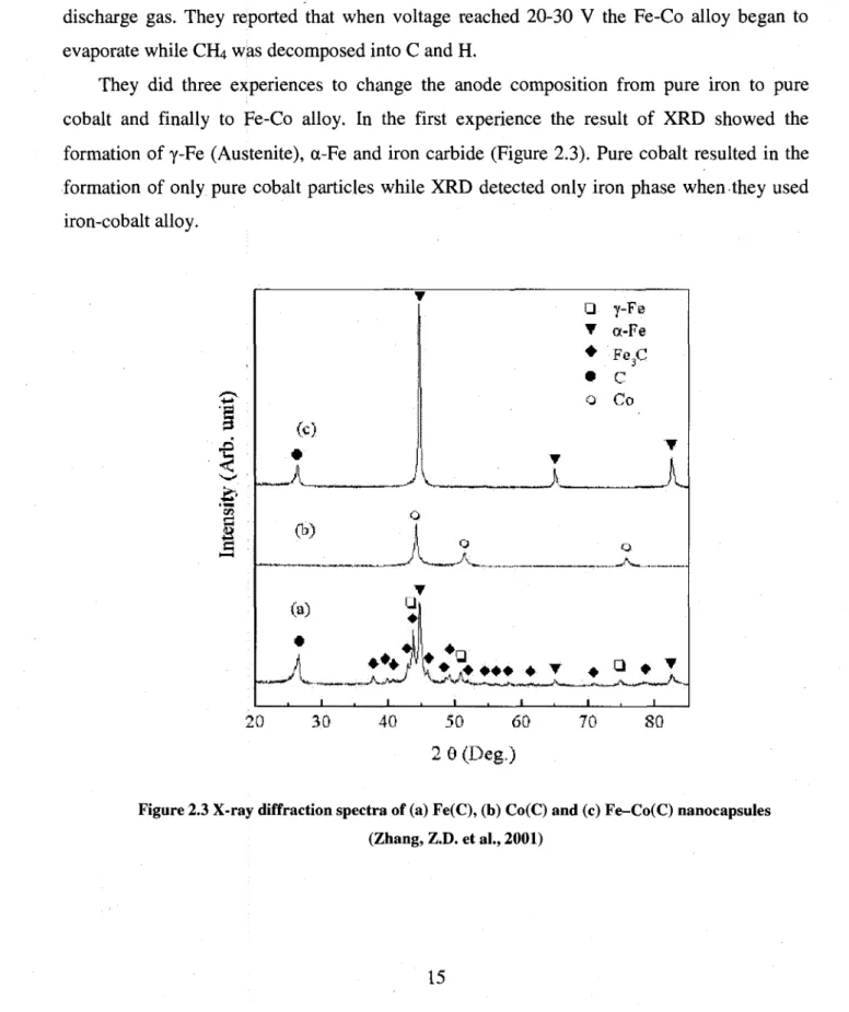
Zhang et al tried to synthesize Fe-Co(C) nanocapsules by using the same method (Zhang, Z.D. et al., 2001). The modification they applied to classic arc method was to use Fe7oCo3o alloy as anode and graphite as cathode. They also mixed He with 30% of CH4 and used it as discharge gas. They reported that when voltage reached 20-30 V the Fe-Co alloy began to evaporate while CH4 was decomposed into C and H.
They did three experiences to change the anode composition from pure iron to pure cobalt and finally to Fe-Co alloy. In the first experience the result of XRD showed the formation of y-Fe (Austenite), a-Fe and iron carbide (Figure 2.3). Pure cobalt resulted in the formation of only pure cobalt particles while XRD detected only iron phase when they used iron-cobalt alloy. g
I
• *•«1
(c) (b> (a) *J\~
i
i
• • • • • T Q • • • O y-Fe a-Fe Fe3C C CoX
a * • • • 20 30 40 50 60 2 9 (Deg.) 70 SOFigure 2.3 X-ray diffraction spectra of (a) Fe(C), (b) Co(C) and (c) Fe-Co(C) nanocapsules (Zhang, Z.D. et al., 2001)
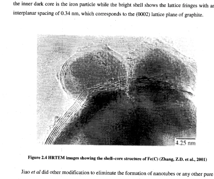
They used HRTEM to show the core-shell structure of produced particles. In Figure 2.4 the inner dark core is the iron particle while the bright shell shows the lattice fringes with an interplanar spacing of 0.34 nm, which corresponds to the (0002) lattice plane of graphite.
Figure 2.4 HRTEM images showing the shell-core structure of Fe(C) (Zhang, Z.D. et al., 2001)
Jiao et al did other modification to eliminate the formation of nanotubes or any other pure carbon composition (Jiao, J. et al., 1996). They used a graphite rod of 6.5 mm diameter as cathode and a graphite crucible with 25 mm inner diameter, filled with selected bulk material such as iron, cobalt or nickel, as anode. FE-SEM result (Figure 2.5) shows that no nanotube is produced and that the powder only consists of spherical particles.
Figure 2.5 Encapsulated iron nanoparticles (Jiao, J. et al., 1996)
They also reported results of XRD, and showed that when iron is filled into the crucible the produced powder contains, of y-Fe (austenite) and a-Fe. They argued that the formation of austenite which is a metastable phase is due to rapid helium quench. They found no iron carbide in their produced powder.
2.6. Thermal plasma
2.6.1. The plasma state
Materials in plasma state exhibit special characteristics which make scientists consider them as a forth state of materials beside solids, liquids and gases. These special characteristics are due to the presence of considerable amount of free electrons and ions in the plasma. As an example, free ions and electrons increase the electric conductivity of plasma to those of metals. Properties of plasma will be separately discussed in subsequent pages.
Plasma produced by electric discharges can be divided in two categories; "thermal" or "equilibrium" plasma and "cold" or "nonequilibrium" plasma.
In a thermal plasma the temperature of electrons is equal to that of ions, atoms and molecules (heavy particles), therefore; there is a local thermodynamic equilibrium in the gas. This equilibrium is called local because of the high temperature gradient in plasma which causes local deviation from complete equilibrium. Thermal plasma is used because of its high
energy density mostly in material processing like particle synthesis, spheroidization, densification or protective layer deposition.
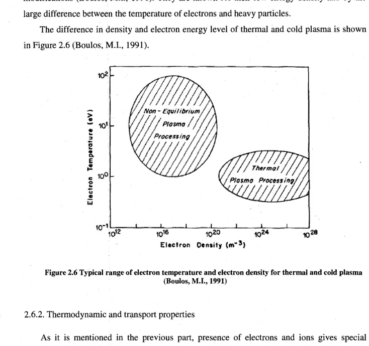
Cold plasmas are used for etching and deposition processes and in plasma surface modifications (Boulos, M.I., 1991). They are known for their low energy density and by the large difference between the temperature of electrons and heavy particles.
The difference in density and electron energy level of thermal and cold plasma is shown in Figure 2.6 (Boulos, M L , 1991).
Electron Oentity iwi"3}
Figure 2.6 Typical range of electron temperature and electron density for thermal and cold plasma (Boulos, M.I., 1991)
2.6.2. Thermodynamic and transport properties
As it is mentioned in the previous part, presence of electrons and ions gives special characteristics to the plasma. In this part, properties of thermal plasma are briefly dis'cussed.
The density of the free electrons and ions in the plasma depends on the temperature and on the gas properties such as its ionization energy and its nature. There are substantial differences between the thermodynamic properties of monatomic and diatomic gases.
Argon is the gas used mostly as plasma gas because it is monatomic and it has a low ionization energy. Due to these properties it is used for plasma generation because it ionizes better than other gases. A diagram of its composition versus temperature is depicted in Figure 2.7. In this diagram plasma is assumed to be in thermodynamic equilibrium.
(a) (b) Figure 2.7 Composition of (a) argon, (b) nitrogen, plasma as a function of temperature (Boulos, M.L,
1991)
Diatomic gases have a more complex composition in plasma state because first they can be ionized to form charged molecules or dissociated to its atoms. The produced atoms can also be ionized at higher temperature. In Figure 2.7 (b) the enthalpy behavior of nitrogen at high temperatures is shown. If we mix a monatomic gas with a diatomic one, we can benefit from advantages of each one.
The advantage of a diatomic gas is its high specific enthalpy as it is showed in Figure 2.8. By means of this property we can have a greater amount of energy per unit mass of diatomic gas at lower temperatures. This property is useful when a high amount of energy is needed and at the same time parts of the system should be kept away from extremely high temperatures. The specific enthalpy of some diatomic gases is presented in Figure 2.8 for comparison with that of monatomic gases.
120 a too $ "*- 80 > 60 «* jE 40
z
20 o - — r ~ T ™ ~ ^ " T -PRESSURE i I Mm . / 1200 ©00 800 600 8 © IE »4 200 0 TEMPERATURE (K x 10s)Figure 2.8 Specific enthalpy of some monatomic and molecular gases as a function of temperature (Boulos, M.L, 1991)
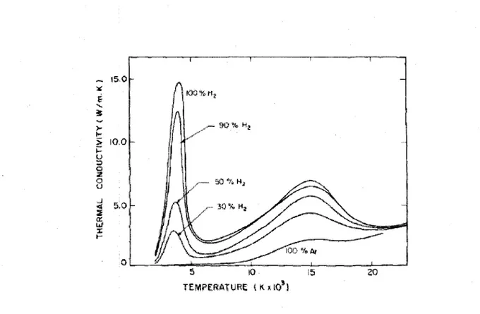
Another important property of gases for plasma processing is their thermal conductivity. Molecular gases near their dissociation temperature show a sudden increase in the thermal conductivity. This increase in thermal conductivity is due to the dissociation of molecules in hot region, which is an endothermic reaction, and then the combination of atoms to form the molecule in a cold region, which is an exothermic process. This mechanism transports huge amounts of energy from the hot zone to the cold zone and causes an increase in the thermal conductivity. Figure 2.9 shows the effect of hydrogen percentage in a Ha/Ar mixture on the thermal conductivity.
T r r
Figure 2.9 Thermal conductivity of H^Ar mixture as a function of temperature (Boulos, M.I., 1991)
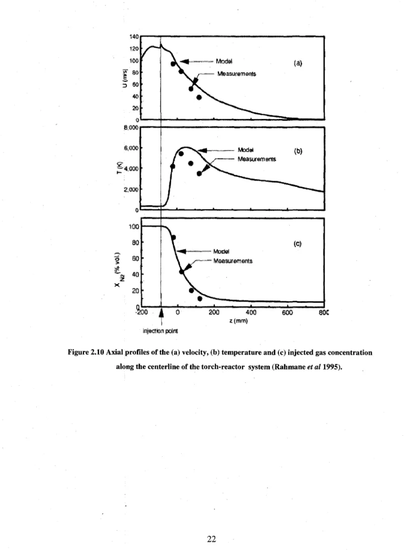
As it is mentioned earlier in this chapter there is an important temperature gradient in the plasma reactor from the plasma "fireball" with temperatures around 10000K and the water-cooled reactor wall at a temperature around 350K which is 10-15 cm away from the plasma fireball. This temperature gradient influences the transfer properties of gases in the plasma reactor. Rahman et al calculated the transport properties of gases in the reactor using the computed temperature field in reactor (Rahmane, M. et al., 1995). The plasma gas was a mixture of argon and hydrogen (5% H2 vol.) with a flow rate of 75 slpm. Nitrogen was injected as a cold gas into the middle of plasma gas to study mixture of cold gas with plasma gases. The power of the d.c plate was held constant at 20 kW. First, in Figure 2.10 the temperature, velocity and gas concentration profile is plotted as a function of the axial distance from the torch exit. Then in Figure 2.11 the transport properties of gases are presented in order to show the variation range of these properties in a plasma reactor. In Figure 2.10 dots show experimental data and the solid line represents modeling results. In Figure 2.11 contribution of laminar and turbulent mechanisms for each property is shown separately.
tajsctiqn pairs
Figure 2.10 Axial profiles of the (a) velocity, (b) temperature and (c) injected gas concentration along the centerline of the torch-reactor system (Rahmane et al 1995).
' O
It
Q 200 • 400 z {mm) 800 injection pointFigure 2.11 Axial profiles of the (a) viscosity, (b) thermal conductivity and (c) mass diffusivity along the centerline of the torch-reactor system.: (dot line) helium, (full line) nitrogen
(Rahmane«?fan995)
2.6.3. Generation of radio frequency (RF) plasma
In RF plasma, an alternating electro magnetic field induces an eddy current in a process gas which is passing through the center of a water-cooled ceramic tube. The alternative electro magnetic field is generated by copper coils connected to a generator. The generator operates between 400KHz to 4MHz (Smith, R.W. et al., 1989a) and that is why it was called
"radio frequency plasma". Today, as radio frequency expanded, inductively thermal plasma is also widely used.
Several gas streams are introduced to the plasma torch. These streams include the powder gas Qi, which is injected axially in the center of the plasma torch. This gas carries injected particles introduced by means of a water-cooled probe. The intermediate gas Q2, is injected to the discharge zone and as the main gas for plasma stabilization. It has both axial and tangential velocity components (Boulos, M.I., 1991). The third and the outer one, is the sheath gas (Q3). It serves to reduce the heat flux from the plasma gas to the confinement tube. The plasma torch dimensions and more details description of injected gases will be presented in chapter 3.
2.6.4. Nanoparticles synthesis by R.F plasma
RF plasma offers an attractive route for nanoparticles production. High temperatures and steep temperature gradients provide a great degree of supersaturation and it is the driving force for nanoparticles nucleation (Pfender, E., 1999). Nucleated particles quench rapidly in the reactor, and do not have enough time for further agglomeration. Another specific characteristic of thermal plasmas is its great energy density, which results in huge throughput in small reactor. In spite of these advantages, processing costs of this method compared to other methods is a major problem, and it must be offset by production of high value-added materials (Pfender, E., 1999).
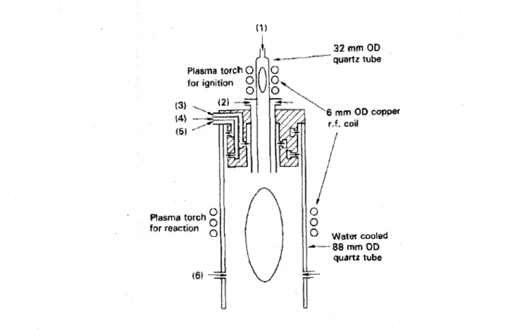
Kameyama et al used a dual-R.F torch for production of iron carbide (Kameyama, T. et al., 1993b). The dual-R.F torch is composed of two electric coils. One coil is installed for primary ignition on the top and the other coil for reaction in the reaction chamber (Figure 2.12). The output of the first coil was 1.0 kW and that of the second one was 10 kW. They injected SiH4-CH4-Fe(CO)5 as precursor.
Plasma torch O for ignition O O (2J —~ Plasma torch for reaction (6! 32 mm OD quartz tube 6 mm OD copper r.f, coil O
o
O vVatei cooled - — 8 8 mm OD quartz tubeFigure 2.12 Schematic view of dual-RF torch (Kameyama, T. et al., 1993b)
Based on inductively coupled plasma spectroscopy they found that about 85% of the produced powder consists of iron-silicon alloy. The rest of the powder is a mixture of elemental silicon, iron, free carbon and silicon carbide.
TEM results of the produced powder shows that the powder contains conglomerates of small particles with diameters between 5 to 50 nm. Figure 2.13 shows particles collected from two different places of the reactor and they both show the same size distribution.
3. EXPERIMENTAL METHODS
In this chapter a description of the experimental methods used in this study will be described. In the first section, the experimental set up is presented. It will be followed by a description of the two (solid and suspension) injection techniques. Several characterization methods are used in this study and a brief description of each of them will be presented in section 3.4. For each characterization technique the operating parameters is also reported. The range of experimental parameters for nanoparticle synthesis is reported in section 3.5 and finally some theoretical backgrounds for factorial design and its interpretation is mentioned in section 3.6.
3.1. Experimental set up
In Figure 3.1 a schematic of the plasma torch, the synthesis chamber and the filters is represented. A PL-50 torch fabricated by Tekna is used in this set up as a device to convert electrical energy to heat. A copper coil in the torch is connected to a RF generator which operates at 3 MHz and a maximum plate power of 60 kW.
The PL-50 plasma torch consists of a 50 mm ID water-cooled ceramic tube. The copper coil surrounds the ceramic tube and conducts the electric current. On the top of the ceramic tube a gas distributor injects three gas streams. Central gas is injected tangentially into the middle of the ceramic tube. The central gas is ionized to form the plasma; hence, Argon is chosen because of its low ionization energy. The second gas injected into the torch is called sheath gas because it protects the ceramic tube from thermal shocks generated by the plasma. The sheath gas is injected along the ceramic tube and it consists of a mixture of argon and 13% of hydrogen. A quartz tube is placed between the central gas and the sheath gas to prevent the early mixing of two gases which could prevent plasma formation because of the high flow rate of sheath gas. The third gas injected into the plasma torch is the powder carrier gas. This gas carries powder precursor which will be injected by means of a water-cooled probe into the middle of the plasma region. A detailed schematic of the PL-50 torch and dimensions of this torch is represented in Figure 3.2.
Central Gas
Sheath Gas
Tekna PL-50
Main chamber
n c
Powder + Career Gas
RF Generator
~3MHz
Vacuum pump
+ Metal filters
+. Auxiliary
Chamber
ri = 1.7 [ran] r2=3,7 [ran] r3 = 18.8 [ran] Ro=25 [mm] Re = 33 [mm] L i - 1 0 [mm] La- 7 4 [mm] LT=250 [mm] w = 2 [mm] Q J 02 Qi LT
Figure 3.2 Plasma torch (Boulos, M.I., 1991)
Precursors are injected into the plasma region by means of an injection probe. Two different injection probes are used in this study, one for suspension precursor injection and the other one for solid precursor. These injection probes consist of a long water-cooled tube while in liquid injection probe a special design is used to atomize the injected suspension. In this probe another tube is located in the central part and liquid will be injected in the inner tube and the atomizing gas on the outer side. At the exit, the inner tube gas will atomize the liquid in the gas blast atomization nozzle (Figure 3.3).
Suspension Atomizing gas
0.5 mm
Suspension injection probe Injection tube Atomization nozzleFigure 3.3 Suspension injection probe (Bouyer, E., 1997a)
Produced powder is deposited on the wall of main and auxiliary chambers and collected by four sintered metal filters. The main chamber is a water-cooled cylinder with 24 cm ID and 103 cm of length. The auxiliary chamber is also a water-cooled cylinder with 20 cm ID and 72 cm of length. The auxiliary chamber is connected to the vacuum line with a control valve in order to adjust the pressure in the main chamber.
3.2. Injection techniques
As mentioned in the previous section, two injection methods are used in this study. In both methods, spherical iron particles with diameter between 1 and 5 u,m are used. In Figure 3.4 SEM images of these particles are shown. This iron powder is purchased from Alfa Aesar Company.
Figure 3.4 SEM images of initial iron particle
As It is shown in this picture, the initial iron particles have smooth surface and are aggregated in some cases. In solid injection method iron powder is injected by means of a positive displacement powder feeder (Sylco CCC Model Mark IX). With this powder feeder iron powder is loaded into the main chamber. The wall of the main chamber vibrates in order to prevent powder agglomeration and bridging during the injection. On the bottom of the main chamber a rotating screw conducts the powder from the main chamber to a cyclone. In the cyclone the iron powder is entrained by the career gas to the injection probe. The injection rate of the powder feeder depends on the rotation speed of the screw and also to the pitch of the screw. The advantage of this powder feeder its the positive displacement mechanism, the bridging effect will become less important during injection of micrometric and nanometric powders. The remaining powder can be removed from the main chamber by tilting the
instrument. Calibration and mass balance is done by subtracting the mass of remaining powder from the initial mass and divide the result by the total injection time.
In the suspension injection technology, the main objective is to produce a homogenized liquid with desired viscosity to prevent the blockage of the injection probe. A stirrer is used to disperse solid particles in the suspension and also an external recirculation circuit is added to remove the liquid from the bottom of the suspension container and to pump it to the top section. Bouyer et al. recommended 0.8 Pa.s as the maximum suspension viscosity for a continuous suspension injection without probe clogging (Bouyer, E. et al. 1997b). Several tests were conducted to find the ideal suspension composition and minimum liquid injection rate for a continuous injection without blockage. It was found that a mixture of 30 gr of iron and 150 ml of mineral oil (Fischer Scientific, CAS : 8042-47-5) is the ideal mixture and minimum liquid injection rate is 5 ml/min. The viscosity of the suspension was not measured by a viscometer in this study but it is recommended to do it, since the viscosity of the suspension affect the diameter of sprayed droplet produced by the atomizer based on Lefebvre equation (Bouyer, E. et al 1997b). The suspension with above composition forms a homogeneous liquid and this assumption can be verified by measuring the amount of solid in remained liquid at the end of experiment. If the solid to liquid ratio at the remaining liquid is equal to the initial ratio, it can be concluded that solids are not accumulated on the bottom of the container and the mixing and the recirculation have provided a good dispersion of solid in the liquid. In order to pump the suspension from the container to the injection probe, a Masterfelx pump (HV-77340-00) is used. The minimum injection rate for this pump is 3 ml/min for L/S 13 tube. The same model pump is used for circulation with a L/S 16 tube and 2000 ml/min flow rate for a high flowrate suspension circulation. The low injection velocity may cause solid sedimentation through the connection tubes and the suspension entering the atomized may not be homogeneous. The weight difference between the connection line before and after each experiment is measured and it did not show any significant difference and it shows that no solid sedimentation has occurred during the injection. However, this overall calculation can not guarantee that each atomized droplet at the atomization probe exit is homogeneous.
3.3. Wet collection method
During the synthesis of nanoparticles in plasma system, the produced particles are deposited on the main chamber wall, the auxiliary chamber wall or they are captured by sintered metal filters installed in the auxiliary chamber (Figure 3.5). In order to recover these powders, the main chamber is separated from the plasma torch, system is dismantled and then the wall of the reactors is brushed to collect the produced powders.
This procedure has two disadvantages. First, some of the produced nanometric particles are pyrophoric and react immediately with oxygen. This collection method exposed particles to the air during the collection procedure. Secondly, they are dispersed into the air during the brushing and could be inhaled by laboratory staff and students.
A device is designed to collect the produced powder with an inert liquid. This prevented particles exposure to oxygen and their dispersion into the air.
Figure 3.5 Two schematic view of liquid injection flange
Figure 3.5 shows a schematic view of the designed flange. This flange consists of two separate parts. When these parts are connected together a narrow channel is formed for liquid circulation. There is a slit on the bottom of this channel where the liquid leaks through and
enters the collection chamber. This flange is installed on the top of the main chamber and the leaking liquid forms a thin liquid film and wets the wall of the chamber. Figure 3.6 shows the liquid film formed for wet collection method.
Up to 90% of the produced powder are collected by this method and separated from the liquid by centrifugation. The collecting liquid must be compatible with produced powder. In our study decalin (Decahydronaphthalene) for wet collection is used because it will be used as the liquid medium in slurry phase FTS reactor. This method has a great advantage for nanoparticle storage and transportation.
The results reported in the next section are obtained by dry collection method to minimize any possible effect of liquid on the produced powder and also to eliminate powder drying which could influence the morphology and chemical composition of the produced powder.
3.4. Characterization techniques
In Table 3.1 a list of characterization methods used in this study is presented. These methods are used in order to determine the morphology, size and chemical composition of the produced particles.
Table 3.1 List of characterization methods and their applications Physical or chemical properties
Morphology and size of particles
Qualitative phase composition
Qualitative phase composition
Crystallite size specific surface area
Method used
• Scanning electron microscopy (SEM) • Transmission Electron Microscopy (TEM)
• High Resolution Electron Microscopy (HRTEM) • High Resolution Electron Microscopy (HRTEM) • X-ray Diffraction (XRD)
• X-ray Diffraction (XRD)
• Thermogravimetric analysis (TGA) X-ray Diffraction (XRD)
BET analysis
Several techniques are used to determine the morphology and size of particles because preliminary results revealed that the powder consists of a broad range of particle size; hence, we used SEM was used for particles greater than 1 micron and TEM and HRTEM for nanometric particles, XRD was used to identify the bulk composition of powder and HRTEM was used to verify the phase of individual particles. TGA was used to measure the total amount of carbon in the produced powder.
X-ray Diffraction
In XRD, a Cu anticathode is bombarded by a beam of electrons. Copper atoms are exited as the result of electron bombardment and when they return to their fundamental state, they emit photons (X-rays). This beam will be collimated to illuminate the powder sample.
In this method the sample preparation consists of hand pressing of 1 to 2 grams of powder into a square shaped sample holder. No grinding before analyse is made because there is no preferential direction in nanometric powders.
X-ray source and X-ray detector are rotated around the sample in order to change the angle between the X-ray beam and the sample. According to Bragg's law (Equation 3.1), in a certain angle, the X-ray will be diffracted after diffraction from the sample. A detector measures the intensity of diffracted beam and intensity and corresponding angle is sent to a computer.
Bragg's law is represented by the following equation:
nX=2d-sm$ (3.1)
Where:
• n is an integer determined by the order given • X is the wavelength of x-rays
• d is the spacing between the planes in the atomic lattice
• 0 is the angle between the incident ray and the scattering planes
By comparing the angles of the intense peaks with the standard data from JCPDS (Joint Committee on Powder Diffraction Standards) files, the existing phases are identified. JADE 6.0 software uses the absolute intensity of several peaks to perform a semi-quantitative analyse.
Transmission Electron Microscopy '
In a TEM, a beam of electrons originate from an electron source and is focused and confined as it passes through electromagnetic lenses and apertures. Thermionic and field emission guns are two kinds of electron sources used in TEM. In a thermionic gun, a filament ( LaBe) is heated until it emits a beam of electron with the desired brightness. In a field emission gun, the electron beam is created by an electrostatic field.
Once collimated, the electron beam reaches the sample. A part of the beam interacts with the sample and deviates or diffracts by the atoms of the sample while the other part is
transmitted through the sample. Another set of electromagnetic lens focuses these different beams and an image of the sample appears on a fluorescent screen or is recorded on a CCD camera.
In this study, a Hitachi H-7500 is used for low resolution TEM imaging and a JEOL JEM 2010F is used for high resolution images. In high resolution images, the lattice d-spacing of particles is observed and compared to other results to determine the composition of well crystallized particles.
Scanning Electron Microscopy
Typically, the same source of electron is used in SEM or TEM. The main difference in SEM is the mechanism of image formation. Once the electron beam, strikes the surface of the specimen, the exited atoms in the specimen return to their stable state. The excess energy of the incident electron is mainly released as secondary electrons or backscattered electrons. The excited atoms return to their fundamental state by emission of characteristic X-Ray or Auger electrons. The intensity of the electrons is used to produce an image of the specimen.
Two types of detectors are used the SEM. Backscattered electron detector is used to detect a fraction of the electron beam which leaves the sample surface after a number of elastic collisions. The number of backscattered electrons depends on the atomic number of the bombarded element, hence; atoms with higher atomic number produce more backscattered electrons and they produce brighter images. Secondary electron detector is another type of detector. Secondary electrons are produced as a result of inelastic collision. After these collisions, the bombarded atom liberates an electron from the outer quantum level to return to its stable state. These electrons have a much lower energy (around 50 eV) than backscattered electrons and they will be attracted by a biased grid placed (200 V) on the secondary electron detector. This grid cannot attract backscattered electrons because they have a too high energy.
In this study a field emission SEM is employed to see the size of the particles and their morphology. The Hitachi H-4700 SEM is used with a 3kV accelerating voltage to take pictures with magnifications up to 150k.
Thermogravimetric Analysis
In TGA analysis, two or three mg of the sample is loaded into the sample holder and placed into an isolated chamber in which 50 ml/min of air is injected. The temperature ramp
rate is set at 10°C/min and it increases from 50 to 960° C. The weight of sample is measured and a diagram of the weight change versus temperature is obtained.
For the synthesized iron carbide particles, carbon atoms will react with oxygen and leave the sample by forming CO or CO2 molecules. During the heating process iron atoms will also transform to iron oxide. It is assumed that when there is no change in weight, all carbon atoms have already left the sample and all iron atoms will have been oxidized completely.
3.5. Operating conditions
In this study two sets of experiments were conducted to investigate the formation of nanosize iron carbide particles. First, preliminary tests were performed in order to find suitable carbon donor precursor. In these tests, 2-butanol was the main source of carbon atoms and glycerol was used to increase the viscosity of the suspension and to increase the settling time of iron particles in suspension. In Table 3.2 the range of parameters used in this study is listed.
Table 3.2 Preliminary tests experimental conditions
Parameters Precursor
Plate Power
Reactor Absolute Pressure
Injection Probe Position*
Injection flow rate
Gas flow rate: Central Sheath Career Condition 2 5 g F e 25ml Glycerol 50ml Butanol 25-45 kW 300 Torr 65 mm 10 ml/min An 23 L/min (STP) Ar:75 L/min (STP) H2 10 L/min (STP) A n i l L/min (STP)
Once the preliminary tests were completed, a 2" factorial design was used to identify the preferential operational conditions. More details of the experimental runs are given in the next section. In Table 3.3, plasma parameters ranges in this section are listed.
Table 3.3 Experimental parameters for factorial design runs
Parameters Precursor
Plate Power
Reactor Absolute Pressure
Injection Probe position
Injection flow rate
Gas flow rate
Condition 60gFe 300 ml mineral oil 25-55 kW 300 Torr 65-75 mm 5-10ml/min Idem Table 3.2
The effect of injection of gaseous carbon donor precursor is also investigated in the third part of this thesis. Experimental parameters used in this section are presented in Table 3.4.
Table 3.4 Solid injection experimental conditions
Parameters Precursor
Plate Power
Reactor Absolute Pressure
Injection Probe position Gas flow rate:
Condition Fe: 3-4.5 g/min C2H2: 0.3-6 L/min (STP) 45 kW 300 Torr 65 mm Idem table 3.2
3.6. Experimental design
In this study, a 2k factorial design was used to investigate the effect of plasma processing
parameters on the conversion of iron to iron carbide. 2k factorial design is mostly used to
investigate the interaction effect of the factors in response.
2k factorial design is a useful method in early stages of experiments, when many factors
may influence the final results (Montgomery, D., 2001). There is also mentioned that this design is widely used in factor screening experiments.
Plate power, injection probe position and injection rate are three factors selected for a factorial design because of their possible influence on plasma temperature and residence time of particles in the plasma zone.
One of the main criteria to consider in factorial design is the increase of the distance between low and high level of design factors. Low level and high level of each factor is determined considering the operational range of plasma torch and plasma stability (Table 3.5). More detail of levels determination is given in the next chapter.
Table 3.5 2 statistical factorial design
Parameter Plate power kW
Injection flow rate (ml/min) Probe position Coded factor A B C Low level 25 5 6.5 High level 55 10 7.5
Statistical analysis is done using Design Expert software 6.0.1 version developed by Estate Ease Inc. This software produces the ANOVA table and performs other calculations related to factorial design. Obtained results are presented and interpreted in chapter 4.
4. RESULTS AND DISCUSSIONS 4.1. Overview and objectives
Production of nanometric iron carbide particle is the goal of this project. Several factors like nature of the precursor, injection flow rate, plate power and probe position are among the main factors which may influence the conversion extent and the size of the produced particles. The objective of this section is to investigate the effect of process parameters on conversion and size distribution of the produced particles. The effect of injected precursor nature by using suspension and solid injection techniques are also determined. Each of these methods has its own advantages and disadvantages and may produce different results.
4.2. Suspension Injection: Preliminary results
4.2.1. Objectives
The objectives of this section are to find out the feasibility of iron carbide synthesis in the plasma reactor. Thermodynamic analysis is used to investigate iron carbide formation at high temperatures and some predictions are made based on these results. Preliminary tests are also done to verify these predictions in practice. The possible operational conditions and solve the technical problems which may happen during the experiments are the main target of this work.
4.2.2. Thermodynamic analysis
Thermodynamical analysis can help predict the formation of different phases at the plasma reactor conditions. As it is shown in Figure 2.10, temperature changes extensively in the reactor; hence, the injected particles are exposed to different temperature zones. It is assumed that the system will reach equilibrium very fast at high temperatures, hence the thermodynamic equilibrium state of the system can be used to predict the final product in the reactor. To consider this assumption, it is supposed that the quench will stabilize the high temperature formed phases as room temperature metastable phases.
Zhao et al compared two different modeling results in their article (Zhao, G.Y. et al., 1990). In the first modeling result, the authors assumed that species are in chemical