HAL Id: hal-03120776
https://hal.archives-ouvertes.fr/hal-03120776
Submitted on 25 Jan 2021HAL is a multi-disciplinary open access
archive for the deposit and dissemination of sci-entific research documents, whether they are pub-lished or not. The documents may come from teaching and research institutions in France or abroad, or from public or private research centers.
L’archive ouverte pluridisciplinaire HAL, est destinée au dépôt et à la diffusion de documents scientifiques de niveau recherche, publiés ou non, émanant des établissements d’enseignement et de recherche français ou étrangers, des laboratoires publics ou privés.
Putting the End-User in the Loop in Smart Ambient
Systems: an Approach based on Model-Driven
Engineering
Maroun Koussaifi, Jean-Paul Arcangeli, Sylvie Trouilhet, Jean-Michel Bruel
To cite this version:
Maroun Koussaifi, Jean-Paul Arcangeli, Sylvie Trouilhet, Jean-Michel Bruel. Putting the End-User in the Loop in Smart Ambient Systems: an Approach based on Model-Driven Engineering. [Research Report] IRIT/RR–2020–06–FR, IRIT - Institut de Recherche en Informatique de Toulouse. 2020. �hal-03120776�
Putting the End-User in the Loop
in Smart Ambient Systems:
an Approach based on
Model-Driven Engineering
IRIT/RR–2020–06–FR
May 2020
Maroun KOUSSAIFI,
Jean-Paul ARCANGELI,
Sylvie TROUILHET,
Jean-Michel BRUEL
Institut de Recherche en Informatique de Toulouse - UMR 5505
Université Paul Sabatier, 118 route de Narbonne, 31062 TOULOUSE cedex 4
Abstract
At the heart of cyber-physical and ambient systems, the user should permanently benefit from ap-plications adapted to the situation and her/his needs. To do this, she/he must be able to configure her/his software environment and be supported as much as possible in that task. To this end, an intel-ligent “engine” assembles software components that are present in the ambient environment at the time and makes unanticipated applications emerge. The problem is to put the user “in the loop”: pro-vide adapted and intelligible descriptions of the emerging applications, and present them so that the user can accept, modify or reject them. Besides, user feedback must be collected to feed the engine’s learning process. Our approach relies on Model-Driven Engineering (MDE). However, differently from the regular use of MDE tools and techniques by engineers to develop software and generate code, our focus is on end-users. Models of component assemblies are represented and made editable for them. Based on a metamodel that supports modeling and description of component-based ap-plications, a user interface provides multi-faceted representations of the emerging applications and captures user feedback. For that, we have developed a solution based on several domain-specific languages and a transformation process, based on the established MDE tools (Gemoc studio, Eclipse Modeling Framework, EcoreTools, Sirius, Acceleo). It works in conjunction with the intelligent en-gine that builds the emerging applications and to which it provides learning data.
Keywords
Ambient systems, model-driven engineering, user in the loop, software composition, service com-position, service description, emergent software.
Chapter 1
Introduction
Applications of the Internet of Things, ambient and cyber-physical systems consist of fixed or mo-bile, connected devices. These devices host independently developed and managed software com-ponents that may be assembled to build distributed applications. Due to mobility and separate man-agement, devices and software components may appear and disappear without foreseeing these dynamics. Hence, the environment is open, and its changes are out of control.
Humans are at the core of these dynamic systems where they may use applications at their disposal. Ambient intelligence aims to offer them a personalized environment adapted to the current situation and their needs, i.e., to provide them the right applications at the right time, with the least effort possible. User control on their environment is of the highest importance [1]: users must be able to configure it and be as much as possible supported in that task.
To this end, our team is exploring and designing an intelligent solution in which software com-ponents are dynamically and automatically assembled to build composite applications and so cus-tomize the environment at runtime: for example, a standard interaction component present in a smartphone (e.g., a Slider or a Speech Recognition component), a software Converter and a con-nected Lamp can opportunely be assembled and provide the user with an ambient lighting control service when entering a room. This intelligent solution is supported by a middleware, called Op-portunistic Composition Engine (OCE) [2], in line with the autonomic computing principles: OCE senses the existing components, decides and plans opportunistic assemblies of components, and fi-nally proposes them to the user. OCE only pushes application plans, i.e., models that are realized only when the user accepts.
Such an approach is disruptive: unlike the traditional goal-directed top-down mode, applications are built on the fly in a bottom-up manner from the components that are present and available at the time, without the user needs to be made explicit. That way, composite applications emerge from the environment, taking advantage of opportunities as they arise.
Here, contrary to the traditional SOA (Service-Oriented Architecture) paradigm, the user does not specify a service or search for it in “pull mode”, but context-adapted applications are provided in “push mode”. In the absence of prior explicit guidelines, OCE automatically learns the user’s prefer-ences according to the situation to make relevant decisions later and maximize her/his satisfaction. Learning is achieved online by reinforcement [3] from the inputs of the user who is put in the loop [4]. This way, the engine assures proactivity and runtime adaptation in the context of openness, dynamics, and unpredictability.
This report details the way we reinforce the place of the user in the engineering loop. Opportunistic composition principles and OCE design are out of scope. The emerging applications must be pre-sented in a useful and understandable way to assist the user efficiently. Also, user feedback must be collected to feed OCE’s online learning process. For that, our approach relies on Model-Driven
Engineering (MDE). The initial idea was to be able to quickly transform composition data provided by OCE into graphical representations of the composite applications. The additional benefit is that, once you get this model representation, you can: (i) provide multiple syntactic representations of the composite application (e.g., component-based, graphical, textual); (ii) generate complementary rep-resentations (e.g., dynamic view of the application, rule-based description); and (iii) formally capture the user manipulations of the model. Our solution consists of a set of languages and transformation processes. We propose an editor that allows the user to be aware of the emerging applications, to understand their function and use, and to modify them if desired. From her/his actions, without overloading her/him, feedback data are extracted and returned to the engine. MDE mainly targets application designers and developers. The originality of our approach is that the models are dedi-cated to application end-users. It brings both new advantages and new challenges that we detail in this paper.
The remaining of this report is organized as follows. Chapter 2 briefly introduces the principles of component-based software engineering (CBSE), model-driven engineering (MDE), and end-user programming (EUP). Chapter 3 analyzes the problem and the requirements. In Chapter 4, the moti-vations for using MDE are examined, then our contribution is detailed and illustrated using an ap-plication example. Our prototype implementation and validation are described in Chapter 5 where other application examples are presented. Chapter 6 analyzes the related work. At last, in Chapter 7, the contribution is summarized, and some future works are discussed.
Chapter 2
Background
2.1
Component-Based Software Engineering (CBSE)
Software components are loosely coupled runtime entities that may provide services specified by interfaces and, in turn, may require other services [5]. Unlike objects, they bring therequired services at the same level as theprovided ones. Fig. 2.1 shows a Converter component represented in UML: provided services (here, the Convert service) are pictured by a bullet and required services (here, the Order service) by a socket. Components, which implementation is hidden, are reusable building blocks. To build applications, they are assembled by binding required to provided services if they match. CBSE involves both developing components individually and building assemblies by using or reusing components. Usually, a middleware supports component deployment and integration.
Figure 2.1: UML representation of a Converter component
2.2
Model-Driven Engineering (MDE)
MDE is a software development methodology that focuses on creating and exploiting domain models related to a specific problem. Software developers (SDs) use them to create abstract descriptions of the software, facilitating the generation of implementation code [6].
At the core of MDE, there are modeling languages (e.g., UML) that are typically defined as meta-models. SDs use these languages to formalize application requirements, structures, and behaviors within a particular domain. Formal rules can be defined to verify that the instances comply with the metamodel (e.g., using Object Constraint Language – OCL). Those rules are added to the metamodel to perform model-checking and detect and prevent many errors before code generation. Most of the time, the abstract syntax is defined using metamodeling by specifying the structure of the modeled system (e.g., building a class diagram that characterizes logical object structures). Metamodeling is also used to define the concrete syntax and customize the generated code.
A substantial benefit of MDE sets in model transformation engines that are used to produce vari-ous types of artifacts, such as source code, deployment descriptors, or other models. For example,
Acceleo [7] is a model-to-text transformation tool that SDs use to generate code. Another MDE fea-ture is the possibility to define Domain-Specific Languages (DSLs). A DSL is a dedicated language (could be for programming, modeling, specifying) devoted to expressing and solving problems in a specific domain [8]. By defining the actions that can be done by SDs, it allows them to manipulate and edit particular models. Finally, to manage models, SDs use model editors, that may be graphical or textual depending on the DSL.
2.3
End-User Programming
End-User Programming (EUP) proposes a set of techniques that enable end-users to create their applications for personal use [9]. EUP is part of End-User Development (EUD) that aims to involve users in application design and development, not only at design time but also at operating time. According to [10], which reviews different projects in particular concerning mobile applications, a possible motivation is that “regular development cycles are too slow to meet users’ fast changing requirements”.
Depending on the solution, end-users may use natural language, visual, or simplified programming techniques e.g., “low-code” development platforms and languages such as Scratch or Blockly [11]. Conventional approaches are based on components or rules, e.g., trigger-action rules that define the action to carry out when the rule is triggered [12]. Besides, some works explore the use of MDE to increase end-user involvement in the use of an application, for example, in application gamification [13].
Chapter 3
Problem statement and requirements
In the absence of prior specification, emerging applications are unknown a priori and possibly sur-prising. Yet, the user must be aware of them, arbitrate on them depending on she/he could benefit from, and provide feedback to the intelligent middleware. For that, the user must be put “in the loop” [14].
The fundamental question is, therefore: how to realize the user in the loop and meet the corre-sponding requirements? The rest of this chapter analyzes and sets out these requirements. The next chapter describes our solution based on MDE.
3.1
Presentation
OCE assembles software components that are present in the ambient environment at the time and makes applications emerge. As applications may be unknown by the user, she/he must be informed of both the function of an emerging application and how to use it.
• [R1.1] Functional description. The function of the application must be presented to the user. For example, “The application allows someone to light up the lamp”.
• [R1.2] Usage. The instructions on how to use the application must be presented to the user. For example, “Press the switch to turn ON/OFF the light”.
3.2
Understandability
Depending on the user skills, presentation and assistance to her/him may be more or less efficient. However, a sound understanding by the user of the presented applications is critical. Both for their acceptance and use and the quality of the user feedback. Here, we target average users that are not necessarily familiar with programming and CBSE. For instance, the user may be the inhabitant of a smart house or a public transport traveler in a smart city. Consider a simple assembly consisting of a switch and a lamp. In that case, we would ideally like to tell the user something like “If you click on the switch, the lamp will turn ON/OFF". Another question is related to the complexity of the assembly in the number of components and services.
• [R2.1] Intelligibility. The application description must be understandable by an average user without programming skills.
• [R2.2] Presentation scalability. The description should remain intelligible and useful even when the application has about ten or more components.
3.3
Automated description
The problem lies in the construction of the description of an application, i.e., its computation from the components of the assembly that implements the application, their services and bindings, with-out human support.
• [R3] Automation and composability. Descriptions must be automatically built by combining unit descriptions of components.
3.4
User input and guidance
Whatever OCE decisions and the pushed applications are, application deployment must remain un-der user control. Users should be able to customize the ambient environment by themselves, de-pending on their needs and preferences, and be guided in this task.
• [R4.1] Input. The user must be able to accept the emerging application [R4.1.1], then it is de-ployed, orreject it [R4.1.2], then it is canceled. According to her/his skills, the user should be able toedit and modify an application model [R4.1.3], i.e., create, remove, or change bindings between services.
• [R4.2] Guidance. When editing, the user must be guided, and the correctness of her/his actions must be guaranteed.
3.5
User feedback
Relevance of the applications pushed by OCE depends on the knowledge about the user. This knowl-edge is built by OCE at runtime and evolves dynamically. To learn from and for the user, OCE needs her/his feedback about the applications. But the user must not be overburdened or disturbed. User acceptance, rejection, and modification are the sources of feedback that are expected by OCE about its decisions. Note that a sound understanding by the user about the proposed application ([R2.1]) is mandatory to provide relevant feedback.
• [R5.1] Feedback generation. OCE must get feedback generated from the user’s reactions to the emerging applications.
Chapter 4
Putting the user in the loop with MDE
4.1
Overview
To put the user in the loop and meet the corresponding requirements, we have designed the In-teractive Control Environment (ICE) based on MDE, which works together with the Opportunistic Composition Engine (OCE).
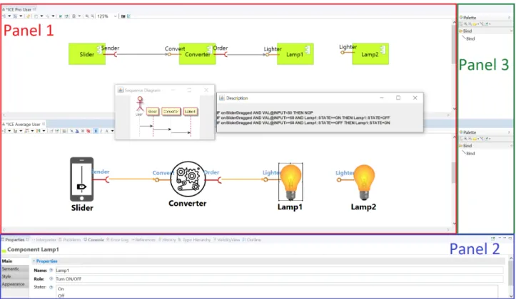
Figure 4.1: The Interactive Control Environment (ICE)
Fig. 4.1 shows a screenshot of the ICE user interface. It is a graphical editor that mainly consists of three panels. Panel 1 displays applications as UML component diagrams. Available components that do not participate in applications are displayed too. Through this panel, the user can accept or reject the assembly. This is an answer to [R4.1.1] and [R4.1.2] requirements. Besides, users that are unfamiliar with component diagrams can request other views of the application: here, a UML sequence diagram and a textual description make more explicit the function of the application and
how to use it. This answers to [R1.1] and [R1.2]. However, depending on the user’s skills, other out-puts are possible in specific languages adapted to the user as shown in the icon-based diagram. This answers to [R2.1]. As the different outputs are computed automatically without user involvement, [R3] is met too.
Moreover, ICE supports application edition by the user. Panel 2 displays the properties of a com-ponent or a service. Panel 3 provides a bind tool for creating bindings between services and so components. The user can also change or delete bindings. This answers to [R4.1.3] and [R4.2] since the editor authorizes only correct user actions. Last, to meet [R5.1], the user’s activities on the as-sembly are captured by ICE, then transformed into feedback and sent to OCE for learning. Note that in such a way, the user is not asked for explicit feedback, so [R5.2] is satisfied.
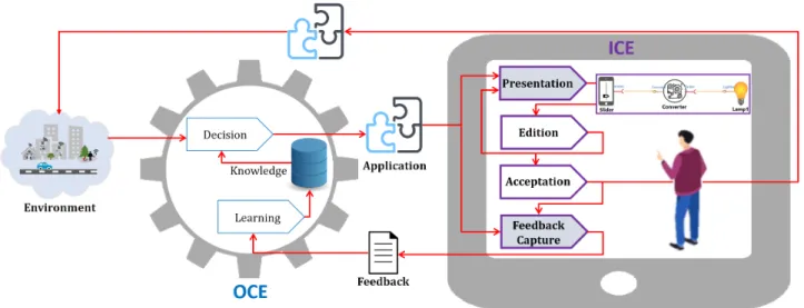
ICE is part of the overall architecture (see Fig. 4.2) we have designed to put the user in the loop [14]: ICE automatically presents emerging application descriptions and captures feedback; besides, the user can edit the assemblies and finally accept them.
Figure 4.2: Overall architecture with the user in the loop
4.2
Motivations for using MDE
At this point, several observations can be made:
1. Basically, OCE designs and produces models. These are models of emerging applications in the form of assemblies of components, all conforming to the same metamodel. Such a model consists of a set of components and a set of bindings between their services. It is prescriptive as it specifies the application to be created but also descriptive of the application to be accepted and deployed [15].
2. The models provided by OCE can be transformed and presented in multiple ways: in differ-ent user-friendly descriptions depending on her/his understanding skills, and as compondiffer-ent diagrams to support component (re)composition by end-users who have programming skills. 3. As a programmer, the end-user must be supported with editing features and control rules that prevent unauthorized bindings. Since the models are subject to user modification, they can also be qualified as explorative [15].
Therefore, we have chosen MDE and the advantages it brings (see Sec. 2.2) to support ICE, i.e., to transform the models designed by OCE into user-oriented models, and conversely transform user-oriented models into both data for OCE learning and deployment scripts. Using MDE for this purpose is unusual: differently from the common use of MDE tools and techniques by engineers to develop software and generate code, we focus on end-users for whom prefabricated assembly models are transformed and represented. To develop our solution, we have used the GEMOC facilities [16], for which our team is an active contributor. ICE consists of an Eclipse Modeling Framework [17] project, where EcoreTools [18] is used to define our metamodel and attach OCL rules to it. We have used Sirius [19] to define the DSLs and create the graphical editor, and Acceleo [7] to support model transformations.
In the following, we expose the different elements of our solution.
4.3
The assembly metamodel
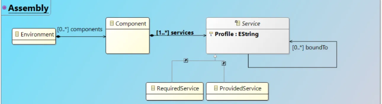
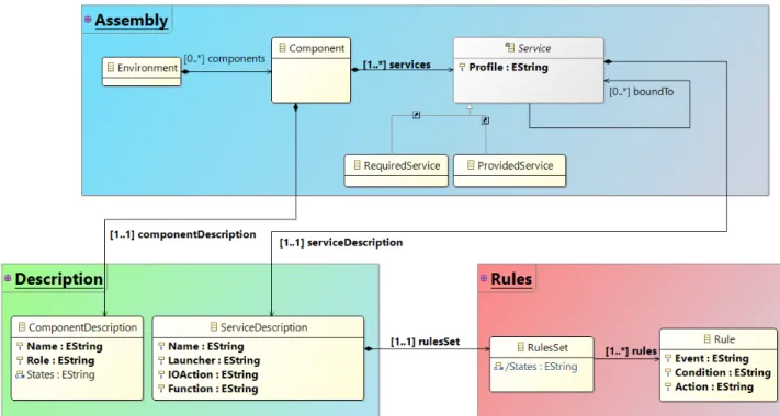
Several metamodels of components and services exist in the literature [20, 21], but they both are too complicated for our needs and do not meet our description requirements. Therefore, we have defined our own (see Fig. 4.3), in line with what has been introduced in Sec. 2.1. It consists of an Environment which contains Components. To be composable, a component has at least one service (a RequiredService or a ProvidedService). A service has one property, boundTo, that defines the bindings to other services once the assembly has been built. Also, OCL invariants describe restrictions on the models, e.g., two required services (or two provided services) cannot be bound together. OCL rules assure that applications are well-formed when emerging or after user input, before their description and deployment.
The Profile attribute defined in the Service class is used to add controls on the edition process. It ensures that: (i) only compatible services are bound together; and (ii) that the maximum number of bindings of a service is respected.
Figure 4.3: Assembly metamodel
The assembly model is part of a more complex metamodel (see Sec. 4.7.2) we have designed to support applications in whole and their transformations into user-oriented descriptions.
4.4
Transformation of OCE outputs to ICE models
To be presented, an OCE output must first be transformed into an internal manipulable and editable form (transformation is a consequent requirement of [R1.1] and [R1.2]). By model-to-model trans-formation, the model provided by OCE is transformed into an ICE XML-based model, both being compliant to the assembly metamodel. Then, the ICE model can be injected into the editor, to be then displayed and possibly modified. This ICE model is also the basis for the processes listed below.
4.5
Assembly representation via domain-specific visual
lan-guages
ICE models represent component assemblies that software engineers commonly draw as UML com-ponent diagrams. To do that and provide users with UML-like representations of the emerging assembly, we have defined a Domain-Specific Visual Language (DSVL) that complies with the UML components notation.
At the top of Panel 1 in Fig. 4.1, there is the editable representation of the entire assembly that achieves the ambient lighting application. For that, a visual representation of each element of the metamodel has been defined. Also, pre- and post- conditions have been incorporated in the DSVL to add control on the edition process, allowing the user to be guided and supervised when editing applications (e.g., the user cannot connect two required services). These conditions are verified on the fly at edition time, so before the OCL rules, to prevent validation errors. This is part of the answer to [R4.2].
Nevertheless, the average user is unfamiliar with component diagrams. In [22], S. Abrahãoet. al. claim that a box in which “Cat” is written –maybe “Lamp1” in our example– may be understood as a “cat” for a software engineer –as a lamp for us–, but it is still a “box” for most people! To address this problem, the above solution can easily be adapted to customize the presentation to the user by replacing the UML representation of a component by an icon that is more explicit for the general public. An icon-based representation of the ambient lighting application is displayed in Fig. 4.1 at the bottom of Panel 1. Such a more intelligible description allows the average user to understand the application better. It contributes to meet the intelligibility requirement [R2.1]. In this way, other DSLs can be proposed that fit users’ skills. The following sections propose complementary answers to meet [R2.1].
4.6
Transformation of ICE model into a sequence diagram
To better inform the user, we explicit how the control passes from a component to another. For that, the ICE model with its bindings between services is transformed into a control model. This model represents how control passes through the components. It is then presented as a UML sequence diagram that shows which service the user directly controls, and how the services interact.
To display the sequence diagram, we coupled ICE with PlantUML editor [23], which provides graph-ical representations of UML sequence diagrams from a text describing the sequence. First, a model-to-text transformation builds a PlantUML-compliant textual model of the application control. Then PlantUML editor is called by ICE to create an image of the sequence diagram (see Fig. 4.1, Panel 1). Other types of diagrams could be produced, e.g., UML communication diagrams, to provide comple-mentary views of the application.
With ICE, depending on her/his preferences, the user can select the type of diagram to generate and display.
4.7
Generation of rule-based application description
Software components transform inputs into inner effects or outputs. Inputs take place when a pro-vided service is required with its parameters or when an internal action or event occurs, e.g., the user moves a slider or pushes a button, or a sensor takes a measurement. Inner effects are changes
of an internal value or state of the component, e.g., a lamp lights up. Outputs are demands of exter-nal services. These transformations are expressed by rules describing how inputs are transformed into effects and outputs. Expressing them is in charge of the component providers. Then, when a component becomes part of an assembly, its rules are combined with the rules of the components it is connected to. For a given assembly, the set of combinations produces a set of rules that describes how the entire application works.
4.7.1
Description using rules
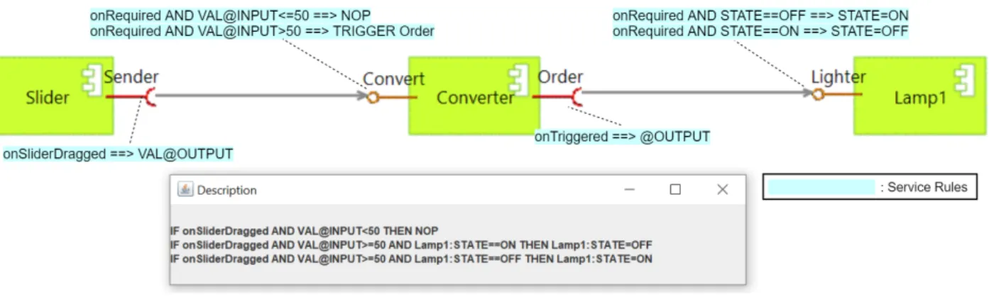
We have defined the description language in [24]. Rules are attached to the services. In Fig. 4.4, each of them is highlighted. For instance, for the Slider component, when the user sets a value by moving the slider, the Sender service is called with this value. In that assembly, the Convert service of the Converter component provides the Sender service that is required by Slider. When needed, depending on the parameter value (more or less than 50), the required Order service may be triggered. The principle is the same for Lamp1, but the effect of the Lighter service call depends on the value of the STATE internal variable that is changed accordingly.
Figure 4.4: Description rules of the ambient lighting application
The pop-up window (in the “Description” frame of Fig. 4.4) shows a pretty-print of the combined result, i.e., the rule-based description of the ambient lighting application that is the function and how to use it. When two services are bound together, their respective rules are combined in pairs to reduce them to a single rule. The latter is then combined with the rules of the next component, and so on. The combination scheme is inspired by thecut rule in mathematical logic: from the rules [Γ =⇒ A, ∆] and [Γ0, A =⇒ ∆0], the rule [Γ, Γ0 =⇒ ∆, ∆0] is inferred. The combination is conditioned by a matching between predefined keywords, e.g.,X@OUTPUT matches Y@INPUT, X andY being variable names. In our example, combining the Sender rule with the two Convert rules produces two rules. One indicates a lack of effect (NOP). The other, which indicates the request for the Order service, is combined with the rule that describes Order. It is combined with those of the Lamp1 Lighter service, producing the two rules that describe the practical effect on Lamp1 if the slider has been set over 50.
Note that the ambient lighting application conforms to a particular architectural style that is called “Pipe & Filter”. However, our solution deals with other composition styles with components that require several services, maybe in sequence, in parallel, or conditionally, and also get and use a result from their requests.
4.7.2
The full metamodel
To achieve the description, the assembly metamodel has been extended to address the description issues. The entire metamodel is shown in Fig. 4.5.
Figure 4.5: The extended metamodel
Every component and service has one description. Therefore, theComponent and Service classes of theAssembly package are composed of their respective description class of the Description package. ComponentDescription consists of three attributes. Name and Role are strings, the latter being a free text describing the component, e.g., Name = “Slider”, Role = “Send the specified value when the slider is moved”. As components may have an internal state, such as a lamp that is ON or OFF,States defines the (maybe empty) set of the possible states, e.g., States = {“ON”,“OFF”}. ServiceDescription consists of four attributes.Name is a string, e.g., “Sender”. Launcher is a key defining what activates the service. It may refer to an external interaction coming from another component, e.g.,onRequired, or to an internal one coming from the component itself, e.g.,onTriggered. For HCI components, it may also refer to user interaction types and take different values, e.g.,onSliderDragged for a Slider. IOAction represents how the service acts on other services, e.g., VAL@OUTPUT means that VAL is given as parameter of a request. IOAction can be empty for a provided service handling only an inner effect on the component, e.g., the Lighter service that only changes Lamp1 state. Last,Function describes the service as a free text, e.g., “Turn ON/OFF”.
In addition, to generate application descriptions, a service description contains a non-empty rule-Set, where the States value comes from the owner component description. A Rule conforms to the ECA model [25]: Event represents what triggers the service; Condition is logical expression e.g., “VAL@INPUT<=50” or “STATE==OFF” (STATE is a keyword which value belongs to States); if Condition is true, the Action which represents the rendering of the service, e.g., “@OUTPUT” or “STATE=ON”, is carried out. Note thatEvent and Action can directly refer to Launcher and IOAction, which are set in the service description.
4.8
Model comparison for feedback generation
Once the user has accepted, modified or rejected the edited assembly, feedback must be generated and given back to OCE. This meets [R5.1] and [R5.2].
Feedback results from the comparison between two models: the initial ICE model (the emerging application model) and the final ICE model (the application model after user inputs). To make this comparison from the XML-based versions of the models, a list of similarities and differences (in term of bindings between the services and components used) is extracted. This list contains: the bindings that have been modified, deleted, and added; the deleted components and those added to the assembly.
From this list, OCE learns by reinforcement the user needs and preferences about the components, services, and bindings [26, 4]: it updates its knowledge so that better applications can be proposed in the future.
4.9
MDE for machine learning
Basically, machine learning [27] aims at building knowledge, i.e., models or patterns of reality. These models are automatically and iteratively constructed in the training phase from training data and generalize them. The goal is to improve later, in the exploitation phase, the learner’s behavior and “performance”.
In Sec. 4.8, we have shown how model comparison supports feedback generation for OCE learning. Here we go beyond the requirements listed in Chapter 3 and take advantage of MDE facilities to design a complementary learning mode.
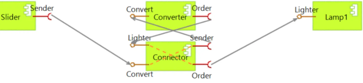
The idea is to provide OCE with ready to use assembly “plans”. The problem is to inject these plans into OCE, which was not designed to manipulate such artifacts. For that, the principle is to reify assembly plans when accepted by the user, i.e., generate special components called connectors. There is no business logic in a connector. It implements the Mediator design pattern [28], and as such, centralizes the interaction logic between the components: it routes service requests from the caller component to the callee and the results in the opposite direction. For that, it gathers all the provided and required services of all the components involved in the assembly. In the connector-based equivalent assembly, the direct links between the components are replaced by links between each component and the connector. Fig. 4.6 shows the connector-based assembly of the ambient lighting application: it is equivalent to that of Fig. 4.1 but interaction between the components is centralized.
Figure 4.6: Connector-based assembly of the ambient lighting application
Using the EMF model factory, a model of the connector component is generated with all of the provided and required services involved in the entire assembly in it. If necessary, a model-to-model
transformation can rebuild the application connector-based model as it is displayed in Fig. 4.6. In a second step, a model-to-text transformation produces the connector implementation code (Java code in our case) and a script for its deployment in the environment. After deployment, it is sensed by OCE and treated as an ordinary software component.
Chapter 5
Implementation and validation
A prototype version of ICE has been implemented. It relies on the Gemoc studio, Eclipse Modeling Framework, EcoreTools, Sirius, and Acceleo. A stable and usable version is available on GitHub1.
ICE provides multi-view representations of applications. It allows to graphically present application structures by means of UML-like and icon-based DSVLs. In addition, how applications work can be described using PlantUML sequence diagrams or in the rule-based language. Besides being informed, the user can modify, accept or reject applications. Furthermore, ICE and the intelligent engine (OCE) have been coupled together. The resulting system is fully operational. Associated with a simulated ambient environment, it works in a loop as shown in Fig. 4.2: applications built by OCE are given as input to ICE, which provides user-friendly editable descriptions, extracts user feedback and supplies it back to OCE. As ICE and OCE work together, ICE is today being used in our team to experiment and validate the OCE solution for learning.
To validate ICE, we have experimented component-based applications arranged according to dif-ferent architectural styles, i.e., difdif-ferent ways to associate components: “Pipe & Filter” like in the ambient lighting application, “Call & Return”, sequential requesting, parallel requesting, etc. For these different cases, on the basis of “test” application models, we have checked:
1. effectiveness and rightness of application structural description using different DSVLs 2. user ability to edit and modify the structural representations
3. operationality of transformations in UML sequence diagrams and rules-based descriptions 4. correctness of user feedback extraction and delivery to OCE.
Intelligibility has been assessed with IT specialists, but so far, we have not asked average users for their opinion. Besides, scalability of the descriptions [R2.2] has yet to be tested.
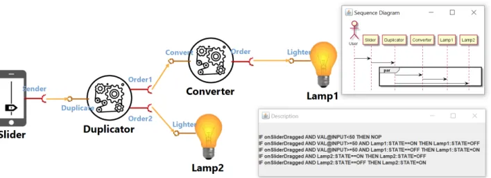
Fig. 5.1 shows another application example, which architecture mixes “Pipe & Filter” and parallel requesting styles: here, the Duplicator component demands the Order1 and Order2 services in par-allel. Using Duplicator, the user has composed an application that commands Lamp1 and Lamp2 in parallel by means of the Slider, so turns on/off the two lamps at the same time. As depicted in Fig. 5.1, in addition to the structural description, ICE allows the user to get a PlantUML sequence diagram with the “par” operator, which expresses the parallelism, and the rule-based description where parallelism is implicit (the default meaning is that all rules are triggered at the same time). In the application sketched in Fig. 5.2, the Sequencer first requests Order1 and next Order2. To express the sequence, the NEXT operator is used; it separates sets of rules that are triggered successively.
Figure 5.1: The parallel ambient lighting application
Figure 5.2: The sequential ambient lighting application
Although the forms of the descriptions are perfectible, especially the one based on rules, experi-mentation has proven the viability of our approach to realize the “user in the loop” and meet its requirements. MDE effectively supports user-oriented presentation and controlled edition of appli-cation models, as well as unobtrusive extraction of user feedback. Model transformation techniques provide multi-view representations of applications that emerge or that the user modifies or builds from scratch. MDE handles DSL definition and easy switching from a DSL to another, so as outputs can be customized for the user.
Chapter 6
Related work
6.1
Description of service- and component-based software
The main purpose of software components and services are composition and reuse. Designers use their descriptions as documentation, which details their intent and use. When engineers specify business processes through service composition, they describe (composite) services, too, before they are processed more or less automatically [29]. Thus, in the traditional top-down mode, demanded composite services are specified at the beginning, so there is no need to produce descriptions after-ward, unlike in the case of opportunistic bottom-up composition.
Service description supports automated service discovery, selection and composition [30]. In that case, descriptions are processed by a program. Descriptions allow service location and use, as is the case for WSDL [31] in the field of Web Services. Descriptions can take more or less sophisticated forms depending on their use. They may only be purely syntactic, e.g., in object-oriented middleware like Java RMI. [32]. Semantic descriptions may be limited to functional signatures with inputs and outputs, possibly extended with preconditions and effects [33]. In addition, they may include the expression of extra-functional properties, i.e., QoS-related properties.
As solutions for service or component descriptions are not user-oriented, they do not meet our pre-sentation and understandability requirements. Moreover, we do not know any solution that satisfies the automation required to build application or service descriptions from the unit descriptions of their components.
6.2
User in-the-loop and end-user development
Even in self-adaptive systems, humans must be in the loop to cope with conflicts and improve adap-tation strategies, and a trade-off should be made between autonomy and human involvement [34]. In [35], the user in-the-loop can set her/his preferences to configure and adapt existing component-based applications. User preferences and profiles can be also be learned by semi-supervised rein-forcement [36].
The AppsGate client-server system [37] empowers end-users with human-machine interfaces to configure and control their smart home. Home inhabitants use visual and pseudo-natural languages to program their ambient environment and add or remove appliances on the fly. They are both assisted by the proposal of possible options and prevented from making errors. In conclusion, the authors state that “it should be possible to augment EUD with machine learning"; then, the be-havior of the inferred services must be “understood by the user and adaptable using the EUD”. In [38], end-users are assisted in service composition by an editor that allows them to specify goals;
here, keyword-based descriptions of available services and ontologies support generation ofad hoc processes that can be customized by end-users.
Thus, there is little or no intelligence (and no emergence) in existing EUD solutions, which do not offer flexibility and customization of descriptions unlike our MDE-based solution.
6.3
Contribution of MDE
Models allow humans to abstract from low-level features and get closer to their business domain. MDE promotes less code and an increased level of abstraction. Since its appearance, it has mainly been used by engineers to guide and support quality software construction.
Combined with CBSE, MDE should help to master the complexity and dynamics of modern software systems [39]. MDE can also support development, deployment and runtime adaptation. Based on UML models and transformations, MDE4IoT [40] assists engineers when designing IoT applications, providing them with abstraction and separation between functional and operational concerns, and supports runtime evolution. In [41], system functionality and adaptations are modeled as a state machine, then model-to-model and later model-to-text transformations support platform-specific code generation. MDE and Models@Runtime also support the design of feedback loops and their execution at runtime in self-adaptive software [42].
Anyway, the role of MDE in the future of IoT and smart systems is still an open question [43]. As far as we know, existing MDE-based approaches do not target users as we do. However, end-users can participate in software modeling in cooperation with software professionals, provided they have development skills [44]. In [35], a UML profile allows capturing variability in a human-readable way that is understandable by non-experts. Furthermore, MDE contribution to the design of user interfaces and their adaptation at runtime is analyzed in [45]. In [22], S. Abrahão et. al. introduce the concept of User eXperience (UX) for MDE: they analyze the challenges and list future work on MDE to meet UX requirements, including identify who the users are, customize tools for domain specifics, and adapt them for acceptability.
Chapter 7
Conclusion and open issues
Ambient systems, with their dynamics and unpredictability, do not allow software design and imple-mentation following traditional development cycles. End-user involvement enables the on-the-fly creation of software adapted to the situation and the user’s preferences and skills. Nevertheless, this user must be supported and helped in the development task. Hence, an intelligent system builds and makes emerge relevant applications that the user has not explicitly asked for nor expected. This report describes an original approach and its framework for presenting emerging applications to the user in an intelligible and manipulable way. It shows how MDE techniques with the definition of dedicated languages help to provide the user with personalized views of applications, as well as the tools that allow them to be modified or even built from scratch. Thus, MDE supports both the controlled construction of applications and the production of descriptive material. Besides, by com-paring and transforming models, feedback is captured and provided to the intelligent system to feed its learning process. Therefore, our original MDE-based approach puts the end-user “in the loop” by giving her/him direct access to the handling of internal application models.
Using MDE techniques and tools, we have implemented and experimented with a fully operational prototype version of ICE. To strengthen our case, intelligibility and scalability of descriptions should be assessed, in particular with average users. Depending on them, other informative views could be provided. A possible lead would be to get closer to block languages [11]. Another, which we plan to explore, is model animation [46].
Our prototype framework has several limitations that we intend to remove. As an illustration, let us mention the one related to the fact that the rule-based descriptions are provided using a unique vocabulary. We made this assumption to simplify rule combinations. Components may be provided by different suppliers who do not have a common vocabulary. For that, we are exploring the use of ontologies to align the terms used in the rules. The first results are promising. More experiment need now to be conducted both in terms of scalability and of stressing the framework with more complex combinations of components.
Bibliography
[1] C. Bach and D. Scapin, “Adaptation of ergonomic criteria to human-virtual environments in-teractions,” inProc. of Interact’03, pp. 880–883, IOS Press, 2003.
[2] W. Younes, S. Trouilhet, F. Adreit, and J.-P. Arcangeli, “Towards an intelligent user-oriented middleware for opportunistic composition of services in ambient spaces,” in Proc. of the 5th Workshop on Middleware and Applications for the Internet of Things (M4IoT’18), (New York, NY, USA), pp. 25–30, ACM, 2018.
[3] R. Sutton and A. Barto,Reinforcement Learning: An Introduction. MIT Press, 2018.
[4] W. Younes, S. Trouilhet, F. Adreit, and J.-P. Arcangeli, “Agent-mediated application emergence through reinforcement learning from user feedback,” in 29thIEEE Int. Conf. on Enabling
Tech-nologies: Infrastructure for Collaborative Enterprises, IEEE, 2020. To appear.
[5] I. Sommerville, “Component-based software engineering,” in Software Engineering, ch. 16, pp. 464–489, Pearson Education, 10thed., 2016.
[6] B. Combemale, R. France, J.-M. Jézéquel, B. Rumpe, J. Steel, and D. Vojtisek,Engineering mod-eling languages: Turning domain knowledge into tools. Chapman & Hall, 2016.
[7] “Acceleo.”https://www.eclipse.org/acceleo/. Accessed: 2020-04-09.
[8] M. Baciková, J. Porubän, and D. Lakatos, “Defining Domain Language of Graphical User In-terfaces,” in2ndSymposium on Languages, Applications and Technologies, vol. 29 of OpenAccess
Series in Informatics (OASIcs), pp. 187–202, 2013.
[9] B. R. Barricelli, F. Cassano, D. Fogli, and A. Piccinno, “End-user development, end-user pro-gramming and end-user software engineering: A systematic mapping study,”Journal of Systems and Software, vol. 149, pp. 101 – 137, 2019.
[10] F. Paternò, “End User Development: Survey of an Emerging Field for Empowering People,” ISRN Software Engineering, vol. 2013, Apr. 2013.
[11] D. Bau, J. Gray, C. Kelleher, J. Sheldon, and F. Turbak, “Learnable programming: Blocks and beyond,”Communication of the ACM, vol. 60, p. 72–80, May 2017.
[12] G. Ghiani, M. Manca, F. Paternò, and C. Santoro, “Personalization of context-dependent appli-cations through trigger-action rules,”ACM Trans. on Computer-Human Interaction, vol. 24, Apr. 2017.
[13] A. Bucchiarone, A. Cicchetti, and A. Marconi, “Exploiting Multi-level Modelling for Designing and Deploying Gameful Systems,” in 22nd ACM/IEEE Int. Conf. on Model Driven Engineering
[14] M. Koussaïfi, S. Trouilhet, J.-P. Arcangeli, and J.-M. Bruel, “Ambient intelligence users in the loop: Towards a model-driven approach,” inSoftware Technologies: Applications and Founda-tions, pp. 558–572, Springer, 2018.
[15] J. Ludewig, “Models in software engineering – an introduction,”Software and Systems Modeling, vol. 2, no. 1, pp. 5–14, 2003.
[16] “The GEMOC Initiative.”http://gemoc.org/. Accessed: 2020-04-09.
[17] “Eclipse Modeling Framework (EMF).” https://www.eclipse.org/modeling/ emf/. Accessed: 2020-04-09.
[18] “EcoreTools - Graphical Modeling for Ecore.” https://www.eclipse.org/ ecoretools/. Accessed: 2020-04-09.
[19] “Sirius.” https://www.eclipse.org/sirius/overview.html. Accessed: 2020-04-09.
[20] J.-Y. Tigli, S. Lavirotte, G. Rey, V. Hourdin, and M. Riveill, “Lightweight Service Oriented Ar-chitecture for Pervasive Computing,”Int. J. of Computer Sci. Issues, vol. 4, no. 1, 2009.
[21] S. Janisch, Behaviour and Refinement of Port-Based Components with Synchronous and Asyn-chronous Communication. PhD thesis, LMU Munich, 2010.
[22] S. Abrahão, F. Bourdeleau, B. Cheng, S. Kokaly, R. Paige, H. Stöerrle, and J. Whittle, “User experience for model-driven engineering: Challenges and future directions,” in20thACM/IEEE Int. Conf. on MDE Languages and Systems, pp. 229–236, IEEE, 2017.
[23] “PlantUML in a nutshell.”https://plantuml.com/. Accessed: 2020-04-09.
[24] M. Koussaifi, S. Trouilhet, J.-P. Arcangeli, and J.-M. Bruel, “Automated user-oriented descrip-tion of emerging composite ambient applicadescrip-tions,” in Proc. of the 31st Int. Conf. on Software
Engineering and Knowledge Engineering, pp. 473–478, 2019.
[25] M. Berndtsson and J. Mellin,ECA Rules, pp. 959–960. Boston, MA: Springer US, 2009.
[26] W. Younes, S. Trouilhet, F. Adreit, and J.-P. Arcangeli, “Principles of user-centered online re-inforcement learning for the emergence of service compositions,” Technical report IRIT/RR– 2019–05–FR, IRIT, May 2019.
[27] T. Mitchell,Machine Learning. McGraw-Hill, 1997.
[28] E. Gamma, R. Helm, R. Johnson, and J. Vlissides,Design Patterns: Elements of Reusable Object-Oriented Software. Addison-Wesley, Pearson Education, 1994.
[29] Q. Z. Sheng, X. Qiao, A. V. Vasilakos, C. Szabo, S. Bourne, and X. Xu, “Web services composition: A decade’s overview,”Information Sciences, vol. 280, pp. 218 – 238, 2014.
[30] Y. Fanjiang, Y. Syu, S. Ma, and J. Kuo, “An overview and classification of service description ap-proaches in automated service composition research,”IEEE Transaction on Services Computing, vol. 10, pp. 176–189, March 2017.
[31] “Web Services Description Language.” https://www.w3.org/TR/wsdl/. Accessed: 2020-04-09.
[32] “Java Remote Method Invocation (RMI).” https://docs.oracle.com/javase/ tutorial/rmi/index.html. Accessed: 2019-01-31.
[33] M. Klusch, “Semantic Web Service Description,” inCASCOM: Intelligent Service Coordination in the Semantic Web, pp. 31–57, Birkhäuser Basel, 2008.
[34] M. Gil, V. Pelechano, J. Fons, and M. Albert, “Designing the Human in the Loop of Self-Adaptive Systems,” in 10th Int. Conf. on Ubiquitous Computing and Ambient Intelligence, pp. 437–449,
Springer, 2016.
[35] C. Evers, R. Kniewel, K. Geihs, and L. Schmidt, “The user in the loop: Enabling user participa-tion for self-adaptive applicaparticipa-tions,”Future Generation Computer Systems, vol. 34, pp. 110–123, 2014.
[36] A. B. Karami, A. Fleury, J. Boonaert, and S. Lecoeuche, “User in the Loop: Adaptive Smart Homes Exploiting User Feedback—State of the Art and Future Directions,”Information, vol. 7, Jun. 2016.
[37] J. Coutaz and J. Crowley, “A First-Person Experience with End-User Development for Smart Homes,”IEEE Pervasive Computing, vol. 15, pp. 26 – 39, May 2016.
[38] H. Xiao, Y. Zou, R. Tang, J. Ng, and L. Nigul, “Ontology-driven service composition for end-users,”Service Oriented Computing and Applications, vol. 5, p. 159, Mar 2011.
[39] F. Ciccozzi, J. Carlson, P. Pelliccione, and M. Tivoli, “Editorial to theme issue on model-driven engineering of component-based software systems,”Software & Systems Modeling, vol. 18, no. 1, pp. 7–10, 2019.
[40] F. Ciccozzi and R. Spalazzese, “MDE4IoT: Supporting the Internet of Things with Model-Driven Engineering,” inInternational Symposium on Intelligent and Distributed Computing, pp. 67–76, Springer, 2016.
[41] M. Hussein, S. Li, and A. Radermacher, “Model-Driven Development of Adaptive IoT Systems,” inMODELS 2017 Sat. Event, vol. 2019 of CEUR Workshop Proc., pp. 17–23, 2017.
[42] T. Vogel,Model-Driven Engineering of Self-Adaptive Software. PhD thesis, University of Pots-dam, Germany, 2018.
[43] A. Bucchiarone, J. Cabot, R. Paige, and A. Pierantonio, “Grand challenges in model-driven engineering: an analysis of the state of the research,” Software and Systems Modeling, vol. 19, no. 1, pp. 5––13, 2020.
[44] F. Pérez, P. Valderas, and J. Fons, “Allowing end-users to participate within model-driven de-velopment approaches,” in2011 IEEE Symposium on Visual Languages and Human-Centric Com-puting (VL/HCC), pp. 187–190, Sep. 2011.
[45] J. Coutaz, “User Interface Plasticity: Model Driven Engineering to the Limit!,” inInt. Conf. on Engineering Interactive Computing Systems (EICS), pp. 1–8, ACM, 2010.
[46] B. Combemale, X. Crégut, J.-P. Giacometti, P. Michel, and M. Pantel, “Introducing Simulation and Model Animation in the MDE Topcased Toolkit,” in4th European Congress on Embedded Real-Time Software (ERTS 2008), SIA, jan. 2008.