HAL Id: hal-02548256
https://hal.archives-ouvertes.fr/hal-02548256
Submitted on 20 Apr 2020
HAL is a multi-disciplinary open access
archive for the deposit and dissemination of
sci-entific research documents, whether they are
pub-lished or not. The documents may come from
teaching and research institutions in France or
abroad, or from public or private research centers.
L’archive ouverte pluridisciplinaire HAL, est
destinée au dépôt et à la diffusion de documents
scientifiques de niveau recherche, publiés ou non,
émanant des établissements d’enseignement et de
recherche français ou étrangers, des laboratoires
publics ou privés.
Using the UML Language to Express the ODP
Enterprise Concepts
Xavier Blanc, Marie-Pierre Gervais, Raymonde Le-Delliou
To cite this version:
Xavier Blanc, Marie-Pierre Gervais, Raymonde Le-Delliou. Using the UML Language to Express the
ODP Enterprise Concepts. [Research Report] lip6.1999.024, LIP6. 1999. �hal-02548256�
Using the UML Language to Express
the ODP Enterprise
Concepts
X. Blanc(*
+), M.P. Gervais(*), R. Le-Delliou(
+)
Laboratoire d'Informatique de Paris 6 ( * ) — 8 rue du Capitaine Scott F75015 PARIS EDF Research Division (+
) — 1, av du Gnl De Gaulle F92141 CLAMART Cedex Xavier.Blanc@lip6.fr, Marie-Pierre.Gervais@lip6.fr, Juliette.Le-Delliou@edf.fr
A b s t r a c t - Specifying i s n o t a gimmick, it is a real discipline t ha t o f f e r s m a n y advantages t o the developers. I t is helpful t o build, m a n a g e a n d d e s c r i b e applications. Standards are now available such as the OMG adoption of the UML notation and the RM-ODP developed by ISO and ITU-T. However these standards are totally independent although they deal with the same topic. In order t o conciliate these two approaches, we propose in this paper a way to use the UML notation to express the RM-ODP enterprise concepts
I.INTRODUCTION
It is a fact that information systems become more and more complex, they solve big problems and enterprises are increasingly dependent on them. In order to develop them efficiently, specifications o f such systems are needed. Having a specification is powerful for anybody who is concerned with information systems. Specifications have many advantages since they clarify understanding for users, control the lifecycle and guide the deployment of the system.
The OMG (Object Management Group), with the standardisation o f UML (Unified Modeling Language) attempts to improve the technology o f specification [1]. UML is a meta-language used t o specify information (like information on a system). UML provides a lot of tools to build specifications. This language enables a developer t o express almost everything. It is a graphic language that is very clear and simple. Another of its advantages is that it is method-free, i.e., every method can be expressed with UML.
UML proposes some graphical blocks to express notions based on objects [2]. It gives blocks for classes, objects, interfaces, component, etc. These
blocks are arranged into diagrams to express semantic notions. The advantages of UML are simplicity, extensibility of the language and possibility of expressing a good deal of notions. The fact that OMG elected this language as a specification language is because of its efficiency.
O n t h e o t h e r hand, ISO (International Standardisation Organisation) a n d ITU-T (International Telecommunication Union — Telecommunication Sector) have elaborated the RM-ODP standards (Reference Model of Open Distributed Process) that focus on an architecture framework for distributed systems and for their specification [3]. These standards provide concepts to specify open distributed systems [4]. They are also method-free, in the sense that any method using RM-ODP concepts can be applied.
The RM-ODP standards suggest to look at the system from five viewpoints and to build five complementary specifications [5]. Each of these specifications presents an abstraction of a system focusing on a specific purpose. According to these five viewpoints, the modeller can build five specifications t h a t a r e independent but complementary. However, the RM-ODP concepts are not trivial, they are very linked together and it is very difficult for a new user to understand them in order to build a specification making use of them. Moreover, the standards are not prescriptive, i.e., no notations are provided to establish specifications.
LIP6 with EDF has started a project that aims t o create a methodology for building distributed systems. This methodology will use the ODP concepts as basic concepts and UML as a specification language.
In this paper, we present the first results of this work that focus on the enterprise viewpoint of the RM-ODP. This viewpoint focuses on the scope, the purpose and the policies of a system. When a modeller specifies a system according to this viewpoint, he/she builds a general representation of the system. This representation could be used in the first step of a method to build distributed system.
In order to establish an enterprise specification, the modeller needs a notation. Thus, we propose t o express the RM-ODP enterprise concepts with the UML notation. For this, we identify some rules o f correspondence between ODP enterprise concept s and UML blocks.
This paper is organised as follows. We first present the main enterprise concepts of the RM-ODP. Then we explain the rules we have defined t o express these concepts with the UML notation. Finally, we illustrate how to use these rules with an example.
II. THE ENTERPRISE VIEWPOINT
In [5], the enterprise viewpoint is defined as a viewpoint on an ODP system and its environment that focuses on the purpose, scope and policies for that system.
A specification of a system in its environment according to the enterprise viewpoint, called an enterprise specification, expresses the behaviour of a system expected by its environment. It also expresses the different policies that apply to the system on behalf of its environment.
It should be noted that an enterprise specification could be made either to construct a new system that will be compliant to the specification or t o represent an existing system. RM-ODP provides concepts that enable a designer to establish such specifications.
Many RM-ODP enterprise concepts are related t o instances (e.g. object, community). In addition, RM-ODP introduces specifications concepts such as:
Template [6]: A template defines how some things can be instantiated. However, a template need n o t provide a complete prescription; information may be derived from the context in
which the instantiation takes place, filling in values for parameters of the template.
Type [6]: A type is a predicate that is satisfied or not satisfied. A type of an <X> characterises a collection of <X>.
For example, if a modeller wants to specify an object, he can do it by describing the object template or describing the object type.
In this document, we display the concepts that are sufficient to build an enterprise specification. We do not display in details all the concepts of the enterprise viewpoint but we assume that most o f enterprise specifications can be expressed with these concepts.
Object [4]: It is the basic concept of the enterprise viewpoint.
An object is a model of an entity. It has an identity, a state and a behaviour. Objects can be used t o represent different levels of abstraction. In a specification, an object can represent a generic car, and in another one, an object can represent a specific car (the blue one, identified 123 ABD 123). The choice of the level of abstraction is under the control of the modeller.
Although the concept of object is the basic notion, an enterprise specification does not include necessarily the description of objects. According t o the level of details the designer wants to specify, he/she can only specify types or templates o f objects rather than objects themselves.
Action [4]: An action is something that happens.
An action can be either internal or interaction. An interaction implies at least two objects. An internal action takes place without the participation of the environment of the object. Actions can be used to represent different levels o f abstraction: an action can be an atomic action (i.e., it cannot be decomposed) or an action can be a sequence of atomic actions. The choice of the level of abstraction is under the control of the modeller. An action type expresses a specification of an action.
Behaviour [4]: A behaviour is a set of actions and constraints on when they appear.
Community [6]: This notion is fundamental in an enterprise specification. When some objects are grouped together to realise a common goal, they constitute a community. An object must belong t o at least one community and can belong to more than one community.
It should be noted that a community C1 could be represented as an object in another community C2. This object is called a CEO (Community Equivalent Object). This CEO is the abstraction of the community C1 inside the community C2.
Objective [6]: An object belongs to a community only if it participates t o the achievement of the objective of that community. Each community h a s i t s o w n objective. Communities do not share an objective, but two communities may have the same objective. Moreover, an objective of a community can be a part of an objective of another community.
Role [4]: We have mentioned that an object can belong to different communities. In each of these communities, the object fulfils a role. Actually, attached to a community is a set of roles. Each of them identifies a behaviour, i.e., the set of actions that must be achieved to carry out the objective. Objects that fulfil these roles then populate the community. A role can be seen as an object type: i f an object fulfils a role, then it can satisfy the type “can realise the behaviour identified by the role”. It should be noted that the CEO is an object. So i t belongs to a “larger” community in which i t fulfils a role. This role, called the interface role, is a representation of some services proposed by the community represented by the CEO.
Policy [6]: policies are applied to objects, roles and communities. There are two kinds of policies, the policies for population and policies for behaviour.
The policies for population give rules to link objects and roles. Examples of such policies are: “an object cannot fulfil two roles that are not compatible” or “in this community, at least one object must fulfil this role”.
The policies for the behaviour give rules on the behaviour of objects or on the behaviour of roles. For example, an action of the behaviour A cannot be done before an action of the behaviour B.
These concepts can be summarised as follows: • A community has one objective.
• To realise this objective, some behaviour must be realised. This behaviour is identified by roles.
• Objects, which fulfil a role in a community, belong to the community.
• Policies can be applied to roles, objects and communities.
These concepts enable the designer to describe c o m m u n i t i e s a n d t h e r e f o r e enterprise specification.
To explain how to use these concepts together, RM-ODP gives structuring rules [6]. We just mention here some of them that are relevant for this paper.
The first structuring rule we will examine is t h a t a n enterprise specification includes community specifications. One of them must be the specification of the community in which the system to be modelled is represented as an object. This community, called the <S>community, is composed of the system (represented as an object) and o f other objects t h a t represent the environment of the system. More generally, it is considered that an enterprise specification is a set of community specifications, one of them must be the <S>community.
The other rule we look at is that a role could be either an actor role or an artefact role. Moreover, an actor role could be either a core role or an environment role.
Briefly, objects fulfilling actor roles can initiate interactions (i.e., they are actors) while objects fulfilling artefact roles cannot.
The distinction between environment role and core role is more interesting to build a CEO. When a community is represented as a CEO in a larger community, only objects that fulfil core roles must compose t h i s CEO. Object fulfilling environment roles belong to the environment o f the community, they do not have to populate the CEO.
These structuring rules help the modeller to use the concepts but they do not provide a design methodology. RM-ODP is method-free, any method using the RM-ODP concepts and the structuring rules can be used to build an enterprise specification.
On another hand, when a modeller wants to make an enterprise specification, he can do it according to two different approaches. One is the role approach, it means that the roles are the basis concepts of the specification. In this approach, the modeller expresses first the behaviour of the system according to roles. Then he associates the roles with objects. The other approach is the object approach, it means that the objects are the basis concepts of the specification. In this approach, the modeller expresses the different entities that belong to the system.
The first approach is sum up in these t w o sentences:
What actions must be made? Which objects do actions?
The second one is sum up in these two sentences: Which are the objects doing something? What do these objects do?
As RM-ODP is method-free, our mapping is also free from method. It can be used by any method that matches to the RM-ODP concepts.
III. EXPRESSING ODP CONCEPTS WITH UML NOTATION
In this part, we will explain our approach to use the UML to express an enterprise specification. We will give rules of correspondence between ODP enterprise concepts and UML blocks.
As it is possible to have different specifications written with the UML language, there could be different ways to map enterprise concepts onto UML blocks [7] [8] [9]. However, we assume t h a t rules we defined ensure consistency and coherence without any lose or addition of semantics. The specification in UML has the same semantic as the specification with natural language.
Object: We can say that an ODP object is like an
UML object [2]. An ODP object is a model of an entity, it has a state, a behaviour and an identity. An UML object has also a state, a behaviour and an identity and it is a model of an entity.
Rule 1: “An ODP object is represented by a UML object”.
In general, an enterprise specification is not composed of objects but it is composed of object templates or/and object types (as in UML, objects are specified by their classes or interfaces).
Action: An action is something that happens. Actions are always associated with at least one object. Actions are ever executed by objects, and we can compare an ODP action to a UML operation [2]. An operation is an abstraction o f something that an object can do. We think t h a t operations can represent the ODP actions. It should be noted that a modeller should deal with action specification or action type rather than with action (ODP action means action occurrence).
Rule 2: “An ODP action is specified with a UML operation”
Role: A role is an identifier for a behaviour, which represents a set of actions and constraints on when they appear. We said that an action is represented by an operation (rule 2); but it seems that no UML concept matches with the RM-ODP role concept. This is why we choose to extend the UML language with a new stereotype of class: the stereotype “role”. A block with this stereotype will represent a role. Semantically, the role notion is close to the interface notion without the notion of services.
Rule 3: “A role is a stereotype of class that expresses a collection of operations. A role can include constraints on operations to tell when they may appear”.
Constraints on operations are represented by UML notes.
Fig. 1 represents a RM-ODP role, named “printer”. The behaviour represented by this role is a single action (print), there is no constraint on this action.
It should be noted that a role can be seen as an object type. So, in an enterprise specification, an object can be specified by a role or by an object template. For example, if A is a role and B an object template, an object O1 that fulfils the role A, i.e. that realises all the actions of the role, can be represented as O1:A, an object O2 that is an instantiation of B can be represented as O2:B while :A represents an anonymous object that fulfils A.
Community: A community is a set of objects. These objects interact to realise the community’s objective. A community specification must express dynamic concepts and static concepts. Dynamic concepts specify the behaviour of the community; they are roles and behaviour policies. Static concepts are policies of population and relationship between roles and object templates. We think that the better way to specify a community with UML is to use a collaboration [ 2 ] . The collaboration can express both dynamic and static concepts. A collaboration is populated with objects; we can express their classes and their interfaces, we can also express the common behaviour of the collaboration. From our point o f view, a collaboration is populated with objects, we can express their templates and their roles, and we can also express the behaviour of the community.
Rule 4: “ A community is specified by a collaboration”
Fig. 2 represents a specification of a community. In this community, anonymous objects must fulfil four roles (A, B, C and D).
The interaction diagram expresses the behaviour of this community, that is, an object fulfilling the role A asks for the do1 action, then an object fulfilling the role B asks for the do2 action etc. As all these objects are anonymous objects, it is possible to have a community that is compliant with this community specification with only one object.
This example of community specification is not complete, the roles A, B, C and D must be specified along with the objective of the community.
Objective: We cannot express the objective of a community with a collaboration. We think that a Use Case can express the objective of a community [2]. A Use Case is a sequence of actions that a system performs and that yields to a result observable from the system environment. From our point of view, a Use Case represents the objective of a community.
Rule 5: “ The objective of a community is represented by a Use Case”
Representing objectives as Use Cases is well-suited with the choice of representing communities as collaboration since a collaboration realises a Use Case as well as a community realises an objective.
The Fig. 3 shows a community specification and i t s objective specification. T h e objective specification is represented as a Use Case.
Fig. 1: An ODP role (printer) with one
2 : 3 : : A : B : :D
Fig. 2: A community with four objects. « role
» printer
Policy: Policies are constraints or rules t h a t
apply to roles, objects or communities. These policies are like annotation on objects or roles, we think that they are similar to notes [ 2 ] . Expressing policies with OCL or other languages is for further study. The Fig. 4 represents a policy applied to a role, this role cannot be fulfilled by human person.
Rule 6: “Policies are represented by notes”
The six rules that we have stated are the basic rules of our mapping. They are sufficient t o express concepts of enterprise viewpoint. But other ones are needed to express the structuring rules of the enterprise viewpoint.
A s mentioned previously, a n enterprise specification is a set of community specifications but one of them must be the specification of the <S>community. This community is composed of one object that represents the system and of other objects that represent the environment of the system.
We suggest to represent the <S>community with a Use Case diagram. We think that the approach of the Use Case diagram is more familiar for the modellers to specify such a community.
UML actors and Use Cases compose a Use Case diagram [2]. UML actors represent the behaviour of an entity that expects a result from the system
and Use Cases represent actions that the system performs. In our mapping, an UML actor represents an ODP environment role and a Use Case represents the objective.
Fig. 5 represents a specification o f a <S>community. Three objects compose this community, t w o o f t h e m represent the environment of the system and the last one represents the system. The objective of the system is represented by the union of the two Use Cases (do1 and do2).
This specification of the <S>community is not complete, the roles envI and envA must be specified.
Rule 7: “An <S>community is represented by a Use Case diagram”
The notions of actor, artefact, core and environment roles are represented by different stereotypes. A core role is represented by a “core role” stereotype.
The way to express the link between a CEO and its corresponding community is that the roles of the CEO are some interface roles of its corresponding community.
Rule 8: “Some interface roles of a community must correspond to the roles fulfilled by the corresponding CEO”.
IV. EXAMPLE: TRAVEL AGENCY
Do something
Fig. 3: A community that realises the objective “Do something”.
« r o l e » printe
Can’t be fulfilled by
Fig. 4: A policy applied to a role
Fig. 5: Specification of an
: envA : envI
do1
A. Descript ion in a Nat ural Language
This example is a classic example in the world o f the distributed systems that everybody can easily understand. This enables one to understand our mapping between ODP and UML.
This travel agency could be an electronic travel agency or a travel agency of the real world. Its domain is transport in general: plane, train, car or boat. The customer asks for a trip and the goal of the agency is to find a trip corresponding to the customer’s wishes and to sell it to him/her. For this, the customer describes the trip and gives the description (with some constraints such as the price) to the agency. The agency does its job and hands an offer to the customer.
The behaviour of the agency is hidden to the customer. Therefore t h e specification will describe it.
The travel agency is an open distributed system. It uses some services of other systems to f ulfil the customer’s wishes. We call “entity” the different actors who act in this system. The customer of the travel agency must be considered as an exception, since he/she is not an entity acting in the system, but a user of it. By extension, we include him/her in the list of the entities given below.
The application is composed of several entities, each of them performs some actions to realise the objective. All these entities can be grouped into a single system or they can belong to several independent systems that interact.
This description is focused on the behaviour o f the application and does not include any information on the membership of the entities. However, these information must be provided when specifying the application with the ODP concepts and with the UML notation.
The entities are:
USR: the user (or customer). He must describe
his trip and gives constraints on it. The customer then gives his request to the travel agency. As mentioned above, the USR belongs to the environment of the travel agency.
PTA: The Personal Travel Assistant is an entity
that receives the request of the USR. It is the only entity that interacts with the USR. For the USR,
the PTA represents the travel entity. The PTA can interact with the DF and with the TBA.
D F : The Directory Facilitor is a database with
links to TBAs. When the PTA checks a trip, it asks the DF to list TBAs.
TBAs: The Travel Broker Agents are entities t h a t
know TSAs. The TBA asks the TSA to give an offer that maps the customer’s request. The PTA deals with the TBAs.
TSA: The Travel Service Agent is the entity t h a t
proposes trips. It can be an Air Company or anything like that.
The behaviour of the travel agency is as follows: 1 . The customer (USR) describes his/her trip
and gives some constraints. He/she gives his/her description to his usual agency.
2. The PTA is the entity that receives the request of the customer. It checks if the request is well formed and then asks the DF to list some TBAs. 3 . The PTA gives to each TBA more information
about the t r ip. In fact, each TBA has its own TSA contact and each TBA will perform research for the trip.
4 . The TBA asks its TSA an offer for the trip. I t gives description and constraints of the trip t o the TSA. The TSA gives an offer and the TBA negotiates this offer to match the customer’s wish. When it is done, the TBA temporarily books the trip. This booking will be confirmed later. Each of the TBAs does this job, then each of them displays its best offer.
5. Each of the TBAs gives to the PTA its best offer. The PTA chooses one offer among them. Then i t tells to the concerned TBA to book definitively the trip.
6. The USR validates the booking.
7 . The TBA books definitively the trip. All the others cancel their booking.
8. The PTA gives the trip to the USR.
This configuration includes one PTA and some TBAs. Each of the TBAs knows some TSAs. Each o f the entities can be localised in a different place.
B. Specificat ion wit h ODP Concept s
We will specify this example with the ODP enterprise concepts. This specification will be done with natural language.
We have written two different specifications. In the first one, the application “travel agency” is considered as a single system that includes all the entities. In the second one, it is composed of t w o systems, one including the entity TSA while another includes all the other entities.
The advantage is that the first specification provides a simple example illustrating the use o f the ODP concepts while the second example provides a more complex specification illustrating interactions between communities.
The notation used is a proprietor notation. Comments will be written in italic while keywords are in bold.
1)First Example: The Travel Agency is a single
syst em including all t he ent it ies.
In an enterprise specification, there must be a <S>community, as explained in the structuring rules, i.e., a community in which the system is represented as an object.
In this example, all the entities belong to the system. So the <S>community is only composed o f the system represented as an object and of the customer (who is not an entity of the travel agency).
This enterprise specification includes t w o community specifications, each of them providing a different level of abstraction. Thus, the community specification named “travel agency as an object”, i.e., the <S>community is very abstract, while the specification of the community named “travel agency in details” is more detailed. This choice enables us to explain the notion of the CEO. Here, the object that fulfils the role “travel agency” in the <S>community is a CEO. The corresponding community of this CEO is the “travel agency in details” community.
Enterprise specification
This enterprise specification is composed of several community specifications.
Community type <travel agency as an object >
This community specification is named <travel agency as an object>. It is the <S>community.
Community behaviour <request for a trip>
USR requests to the travel agency for a trip and then the travel agency offers to the USR a trip that fits his wish.
This is the specification of the behaviour of the community.
Actor role <USR> is an environment role Action <request for a trip>
Involves <travel agency>
The different roles of the community are enumerated: USR is an actor environment role, its action is <request for a trip>. An object that fulfils this role will interact with an object that fulfils <travel agency> role
Actor role <travel agency> is a core role Action <find a trip that conforms to the
request>
Involves <USR>
Community type <travel agency in details>
Community behaviour <find a trip>
The USR requests a trip, then the PTA asks to the DF some TBAs. Each of the TBAs asks to some TSAs to give an offer for the trip. Each of the TBAs proposes its best result to the PTA. The PTA takes the best-proposed result. The PTA gives this best offer to the USR. The user accepts or refuses the offer, if he accepts then the corresponding TBA books the trip to its TSA.
Actor role <USR> is an environment role Action <request for a trip>
Involves PTA
Action <accept or deny an offer> Involves PTA
Actor role <PTA> is a core role Action <ask to the DF>
Involves DF
Action <ask to the TBA> Involves TBA
Action <take the best offer> Involves TBA
Action <give the trip> Involves USR
Actor role <TBA> is a core role
Action <ask to the TSA> Involves TSA
Involves PTA
Actor role <TSA> is a core role Action <offer trip>
Involves TBA
Actor role <DF> is a core role Action <gives TBA>
Involves PTA
Artefact role <TR> is a core role This role represents the trip
2)Second example: The TSA is an independent syst em
In this specification, the TSA is an independent system that interacts with the travel agency system (composed of the PTA, DF and TBA entities).
As this kind of configuration is very frequent, we consider it in order to show how the enterprise viewpoint deals with interactions between systems.
The TSA is an independent system, so it has its own enterprise specification. This specification c a n b e composed o f several community specifications. However, for our purpose that is the specification of the travel agency system rather than the TSA enterprise specification, only an abstract view will be useful. Thus, the <S>community o f t h e TSA specification is sufficient.
This community has two roles, the role of the TSA (the system) represented as an object and the role of the customer. The role of the TSA represents the services t h a t t h e system exports t o its environment and the other role is the environment role that represents the customer.
Enterprise specification
This is the specification of the TSA
Community type <TSA as an object>
Community behaviour <offer trip>
The CUStomer asks for a trip and the TSA tells him if it has such a trip.
Actor role <CUS> is an environment role
Action <ask for a trip> Involves TSA
Actor role <TSA> is a core role
Action <propose trip> Involves CUS
A modeller who wants to specify the travel agency can make use of this TSA specification. To link this specification with the specification of the travel agency, an object of the travel agency community should fulfil the role of the CUStomer of the TSA system.
Enterprise specification
This is the specification of the travel agency.
Community type <travel agency as object >
In this specification, there is the <S>community named travel agency as an object. This community specification does not have to mention that the travel agency interacts with the TSA system, since i t represents the system as an object.
Community behaviour <request for a trip>
USR requests to the travel agency for a trip and then the travel agency offers to the USR a trip that conforms to his wish.
Actor role <USR> is an environment role
Action <request for a trip> Involves <travel agency>
Actor role <travel agency> is a core role Action <find a trip that conforms to the request>
Involves <USR>
Community type <travel agency in details>
This is another community specification that belongs t o t h e e n t e r p r i s e specification. T h i s community specification describes in details the behaviour of the travel agency.
Community behaviour <find a trip>
The USR requests a trip, then the PTA asks the DF for some TBAs. Each of the TBAs asks to some TSAs to give an offer for the trip. Each of the TBAs proposes its best result to the PTA. The PTA takes the best-proposed result. The PTA gives this best offer to the USR. The user accepts or refuses the offer, if he accepts then the corresponding TBA books the trip to its TSA.
Actor role <USR> is an environment role Action <request for a trip>
Involves PTA
Action <accepts or denies an offer> Involves PTA
Actor role <PTA> is a core role Action <ask to the DF>
Involves DF
Involves TBA
Action <take the best offer> Involves TBA
Actor role <TBA> is a core role Action <gives the best offer> Involves TSA
Concerns USR
Constraints Objects fulfilling this role must fulfil the CUStomer role of the <TSA as an object> community.
Here, we specify the fact that objects fulfilling this role must fulfil the role “CUStomer” of the community “TSA as an object”.
Actor role <DF> is a core role Action <gives TBA>
Involves PTA
Artefact role <TR> is a core role
This specification shows how an interaction between two systems can be specified.
C. Specificat ion wit h UML Language
The specifications shown here are semantically the same as those in section 4.2.
1) First Example: The Travel Agency is a single
syst em including all t he ent it ies.
As in part 4.2, the <S>community named “travel agency as an object” has two roles, the role USR and the role named “Travel Agency” (Fig. 6). To complete this specification, the description of the role USR and the role TA must be represented graphically. We illustrate in Fig. 7 the environment role USR with one operation “request for a trip”.
Note that Fig.6 and Fig. 7 are parts of the specification of the <S>community, that is itself a part of the travel agency enterprise specification. The latter includes t h e other community specification named “travel agency in details”, illustrated in Fig. 8 .
As in part 4.2 roles are USR, TSA, DF, PTA and TBA. To have a complete specification, these roles must be specified.
Comments can be put in the specification t o express RM-ODP policies or other things. Here, there is one comment that expresses a population policy.
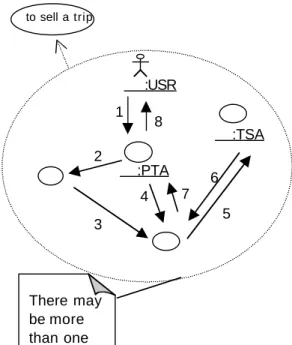
We have identified that in the “travel agency as an object” community, the object that fulfils the role “Travel Agency” is a CEO. Its corresponding community is the “travel agency in details”. The CEO is a conceptual object, composed of a set o f to sell a to sell a trip :PTA :USR :TSA 1 2 3 4 5 6 7 8 There may be more than one « env Request for a trip()
Fig. 7: The role USR Fig. 6: Specification of the
<S>community “travel agency as an
Fig. 8: Specification of the community “travel agency in details”.
objects fulfilling core roles. These are TSA, DF, TSA and TBA.
2) Second Example: The TSA is an independent
syst em.
The specifications shown here are semantically the same as those in section 4.2.
As mentioned in section 4.2, the TSA is an independent system that has its own enterprise specification. This specification can be composed o f several community specifications. As we are interested in specifying the travel agency system, we choose to bring only a part of the enterprise specification of the TSA, that is its <S>community specification, illustrating in Fig. 9 . This community has two roles, the role CUS that represents the customer and the role TSA representing the system.
This specification of the TSA is used by the modeller who wants to specify the travel agency system. The specification of the <S>community “Travel agency as an object” is illustrated in Fig. 10. It is the same as the one obtained in the first example (i.e., travel agency as a single system t h a t include all entities) since the <S>community provides a very general view of the travel agency. Differences between the two examples appear only at a more detailed level, i.e., in the specification “travel agency in details”, illustrated in Fig. 11.
In this specification, the object fulfilling the role TSA must also fulfil the role CUS. This role belongs the community “TSA as an object” (Fig. 9). Thus, there is an interaction between communities. An object belongs to the “travel agency in detail” community and it belongs to the community “TSA as an object” too. This means that if a community is compliant to this specification, one of its object must belong to a community that is compliant t o the “TSA as an object” community.
V.CONCLUSION
The two examples of enterprise specification presented above, first in natural language then in our UML mapping enable us to conclude t h a t specifications with UML is simpler and clearer. I t is simpler because it takes the advantage of the UML notation that is to be very simple and very clear. Thus this mapping offers a pleasant way to express specifications with RM-ODP concepts. Specifications take advantages of this mapping as the UML notation gives them simplicity and they are based on international concepts thanks to RM-ODP.
Another advantage of this mapping is that it is free from method. Every method that uses the RM-ODP concepts can use this mapping.
VI. FURTHER WORK
The rules of correspondence presented in this paper provide a notation t o the RM-ODP enterprise concepts. Some extensions need to be provided, such as a more appropriate notation for policies than UML notes currently used. We are going to investigate the use of a language such as OCL t o express policies. These rules o f correspondence also constitute a f irst step in the creation of a method compliant with the RM-ODP concepts and architecture.
This method will benefit from a graphical notation (a little extension of the UML ones) as :CUS
Fig. 9: Specification of the
<S>community “TSA as an object”.
to sell a
Fig 10: Specification of the
<S>community “travel agency as an To sell a trip
:USR
:TSA & CUS 1 2 3 6 7 8 It may occur more than :PTA 5 4
Fig. 11: Specification of the community “travel agency in Propose a
well as the use of the RM-ODP standards. The latter provides a major advantage with its concept of viewpoint and moreover the correspondence between viewpoints. With such correspondences, computational (or engineering) aspects can emerge from the specification in the enterprise viewpoint or vice versa.
Establishing such correspondence rules is the next step of our work.
REFERENCES
[1] OMG UML Specification (draft) v1.3alphaR5 1 9 9 9
[2] G. Booch, J.Rumbauch, I. Jacobson “The Unified Modeling Language User Guide”, Addison Wesley
[3] ISO/IEC, “ISO/IEC 10746-1 Information Technology Basic Reference Model of Open Distributed Processing Part 1: Overview ” ISO ITU-T X.901 ISO/IEC DIS 10746-1, 1 9 9 6
[4] ISO/IEC, “ISO/IEC 10746-2 Information Technology Open Distributed Processing Reference Model: Foundations”, 1 9 9 6
[5] ISO/IEC, “ISO/IEC 10746-3 Information Technology Open Distributed Processing Reference Model: Architecture”, 1 9 9 6
[ 6 ] ISO/IEC JTC1/SC7/WG3 3N65 “Working Draft Washington Output 1 9 9 9 ”
[7] OMG/UML, “UML Notation”
http://www.rational.com/uml/html/notation, 1 9 9 7
[8] M.Belaunde, J-M. Cornily, E. Debeau, “An RM-ODP based approach to modelling distributed systems using UML and associated tools.” PARIS Software & Systems Engineering.December 1998. [ 9 ] J . Oldevik, A-J. Berre, “UML-Based methodology for distributed systems” EDOC’98