This is an author-deposited version published in: http://oatao.univ-toulouse.fr/ Eprints ID: 4196
To cite this document:
MARGER Thibaut, POMMIER-BUDINGER Valérie,
MARE J-Charles, MALBURET François. Designing redundant metering valves for
hydraulic actuators under mixability and low cost-constraints. In: 10th AIAA
Aviation Technology, Integration, and Operations (ATIO) Conference, 13-15 Sept
2010, Fort Worth, United States.
Any correspondence concerning this service should be sent to the repository administrator: [email protected]
DESIGNING REDUNDANT METERING VALVES FOR HYDRAULIC
ACTUATORS UNDER MIXABILITY AND LOW
COST-CONSTRAINTS
Thibaut MARGER
Arts et Métiers ParisTech ; LSIS 2 cours des arts et métiers 13167 Aix en provence, FRANCE
Valerie POMMIER-BUDINGER
Université de Toulouse ; ISAE
10 avenue E. Belin – 31055 Toulouse – FRANCE [email protected]
J-Charles MARE
Université de Toulouse ; INSA, UPS ; Institut Clément Ader
135, avenue de Rangueil, F-31077 Toulouse, [email protected]
François MALBURET
Arts et Métiers ParisTech ; LSIS 2 cours des Arts et Métiers 13167 Aix-en-Provence, FRANCE
ABSTRACT
This article deals with the design of redundant metering valves for mechanically signalled hydraulic actuators. The final aim of the work is to manufacture a new low-cost valve in replacement of the existing expensive valve with an additional leakage requirement in case of seizure. The new valve must ensure the same closed-loop behaviour of the actuator. The article presents the design of the valve according to the actuator specifications and to a criterion of mixability (capacity to replace the existing valve by a new one). The valve pre-design is based on the common sharp edges and rectangular orifice slots combined with a serial restrictor inserted on the supply line. After partial experimental validation, the proposed design process points out the interest of using a trapezoidal slot in order to get the required speed gain over the whole valve opening range. The proposal is validated through the experimental measurement of the actuator no-load speed as a function of the valve opening.
1. Introduction
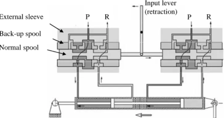
Redundant hydro-mechanical actuators are widely used for position control in critical embedded applications. They typically involve two identical power paths making a tandem actuator (Figure 1). Each path combines a redundant, closed centre, 4 ways metering valve and a hydraulic cylinder [1]. The normal valve involves the main sliding spool and the backup spool that makes the normal valve sleeve. In case of seizure of the normal spool within its sleeve, the backup valve allows
recovering the metering function by moving the backup spool inside the backup sleeve. In normal conditions, the backup spool is hold in position by a spring-box. Its breakaway force fixes the amount of overdrive lever force that is required to open the backup valve when the main valve has seized.
P R P R Input lever (retraction) Normal spool Back-up spool External sleeve spool
Figure 1: Tandem servoactuator in retraction This article deals with the design of redundant metering valves. The final aim of the work is to manufacture new low-cost valves in replacement of the existing expensive valves with an additional leakage requirement in case of seizure.
The design of the valve must meet various requirements among them two are of particular importance [2]:
- the speed gain curve (no load speed as a function of the valve opening) that contributes to the open loop gain of the actuator. As the actuator behaves globally as an integrator, the speed gain curve
influences directly the closed-loop tracking error [3].
- the valve leakage flow in case the main valve has seized at full opening. This prevents excessive flow demand to the hydraulic supply that could lead to a total loss of supply pressure.
The starting point of the study is the specifications of the actuator that are detailed in section 2. The two requirements being considered are the maximal no load speed and the maximal leakage flow rate.
The pre-design process involves for computation the equation of flow through variables orifices [4] and on the equation of the servoactuator speed [5]. The valve slot width appears as a key design parameter of the valve speed gain. In order to meet the new leakage requirement, the common valve design is modified by inserting a fixed restrictor onto the supply line. The diameter of this restrictor appears as an additional key design parameter that modifies as well the speed gain as a side effect. This coupling is addressed in the paragraph 3.
The main difficulty lies in the uncertainty attached to some parameters than cannot be varied by design (e.g. flow number) or that are poorly controlled by the manufacturing process (e.g. effective radius of the orifices edges).
Once completed the pre-design, a valve prototype is manufactured to validate the theoretical results. The differences between predicted and measured maximal speeds are due to parameters uncertainties. As explained in paragraph 4.1, this suggests a first design improvement consisting in a slight adjustment of the restrictor diameter. However, a significant gap remains between the old and the new valve speed gains that is essentially located in the intermediate range of the valve opening. The design is therefore improved in order to modify the shape of the speed gain curve, as described in paragraph 4.2. In such a way, both requirements are met, including the mixability criterion. As a main result of this final step, the common rectangular orifice slots are replaced by trapezoidal slots which sizing is supported by the design process.
2. Work specification
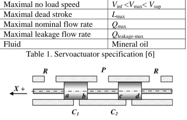
The aim of the work is to design the valve of a servoactuator whose main specifications are given in
table 1. The diagram of the valve is given in Figure 2. P is the supply pressure and R the return pressure. The four metering edges of the valve are called a, b, c and d. When the valve motion is positive (X+), the extension chamber (C1) is supplied and the retraction chamber (C2) is connected to the return line. In order to limit the flow rate consumed by the valve, the restriction is added on the supply line of the valve. The back-up spool guaranties a by-pass function of the valve in case of seizure of the main spool.
Maximal no load speed Vinf <Vmax< Vsup
Maximal dead stroke Lmax
Maximal nominal flow rate Qmax Maximal leakage flow rate Qleakage-max
Fluid Mineral oil
Table 1. Servoactuator specification [6] P
R R
C1 C2
X +
a b c d
Figure 2: Scheme of the valve
Another important specification is the mixability of the new manufactured valve with old valves. This requirement is met if the speed difference between the servoactuator with the new and the old valve is less than 10% of the lower limit of the maximal speed (Vsup) for
±40% of the valve opening (most used range). The speed must be checked in extension as well as in retraction for a tandem servoactuator.
3. Pre-design of the valve
3.1 Required data
The required data for the study are: * for the fluid:
- the density and the kinematic viscosity * for the valve:
-the main spool overlap (to be lower than the half of the maximal dead stroke for each metering edge) -the back-up spool overlap (around ten times the main spool overlap to limit the leakage and to avoid valve openings caused by structural vibrations)
-the diametral clearance of the main spool and of the back-up spool (to be kept as small as possible to limit the leakage) [7]
-the main spool stroke -the number of slots * for the jack:
- the friction force (to compute the speed of the jack) - the piston hydrostatic areas (to compute the speed of the jack)
Two main parameters have to be determined to meet the specifications - the valve slot width and the restrictor diameter - that both influence the maximal speed and the maximal flow rate. The article will show how to compute these parameters from equations of the valve maximal flow rate and of the servoactuator speeds.
3.2 Equation of the valve leakage flow rate
The leakage flow rate is defined as the maximal flow rate when the valve main spool is seized at extreme opening and when the lever is in the initial neutral position (Figure 3). Back-up spool Main spool (1) (2) (3) External sleeve Primary stage Safety stage
(1) lever at neutral position (2) main spool at extreme opening
(3) lever at neutral position and main spool seized at extreme opening
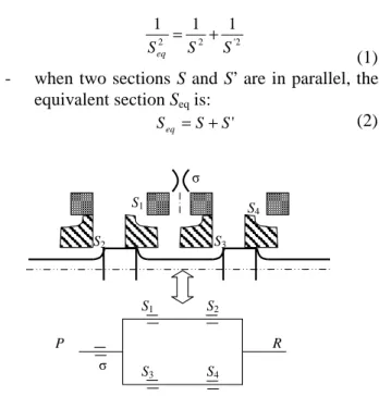
Figure 3: Scheme of the valve main spool In order to compute the flow rate, an equivalent section is needed and obtained from the valve cross-flow sections defined in Figure 4, assuming constant flow coefficient because of the large opening sections (so Cq=Cq∞ in equation)[4]):
- when two sections S and S’ are in series, the equivalent section Seq is:
2 ' 2 2 1 1 1 S S Seq = + (1) - when two sections S and S’ are in parallel, the
equivalent section Seq is:
' S S Seq = + (2) P R σ S1 S2 S3 S4 σ S1 S2 S3 S4
Figure 4: Valve sections in the seized case at extreme opening
The maximal flow rate in the seized case at extreme opening is given by:
) ( 2 max n C S P Rsign P R Q −seizedcase = s q eq − − ρ (3) with:
- Seq: equivalent section of the system described in Figure 4
- Cq: flow coefficient - ρ: fluid density - ns: number of slots
3.3 Equation of the servoactuator speeds
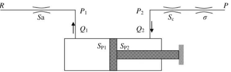
The speed must be computed in extension and in retraction mode. The scheme of the servoactuator in extension is given in Figure 5. P1 Q1 P2 Q2 P R σ Sb Sd SP1 SP2
Figure 5: Functional diagram of a servoactuator with two moving bodies in extension
The flow rates for the edges b and d are computed with the following equations:
(
1) (
1)
2 2 1 sign 2 1 1 1 P P P P S C Q b q − − + = ρ σ (4)(
P R) (
P R)
S C Q2 = q d 2 2− sign 2− ρ (5)where Sb and Sd are the valve opening sections associated to the edges b and d respectively.
In steady state conditions, the actuator speed is given by:
1 1 P extension S Q X& = (6) and 2 2 P extension S Q X& = (7)
where SP1 and SP2 are the piston hydrostatic areas. It is also possible to write the equilibrium equation:
seal P
P PS F
S
P1 1 = 2 2 +2 (8)
where Fseal is the seal friction force.
Then, there are 5 equations (eq. (4) to (8)) and 5 unknown parameters (P1, P2, X&extension, Q1 and Q2). While resolving the system, the servoactuator speed in extension
extension
X& is thus computed.
The methodology to compute the speed in retraction is the same. The scheme of the servoactuator in retraction is given in Figure 6. The flow rates for the edges a and c are computed as for the extension case while taking into account the valve opening sections associated to the edges a and c (Sa and Sc). The equilibrium equation for the retraction case is given by:
2 2 1
1SP 2Fseal PSP
P + = (9)
The servoactuator speed in retraction X&retraction can thus be computed. P1 Q1 P2 Q2 R P σ Sa Sc SP1 SP2
Figure 6: Functional diagram of a servoactuator with two moving bodies in retraction
3.4 Slot width and restriction diameter computation
The aim is to compute the slot width and the restriction diameter. These two parameters influence both the valve maximal flow rate and the servoactuator speed in the different configurations of use. It is not possible to compute the two parameters by solving a system of equations that describe all the configurations and that meet all the required specifications (because of an algebraic loop [8]). An iterative method is proposed to solve the problem and is described in Figure 7:
- the slot width is fixed.
- the restriction diameter is computed by a solver to get a maximal flow rate of Qmax in seizure case at extreme opening.
- the servoactuator speeds are computed in extension and in retraction phases.
- The computed speeds are compared with the specifications. If the results are not correct, another slot width is selected and the computations are re-run. The minimal step on the width slot is 1/100. Otherwise, the desired couple of slot width and restriction diameter is kept as the solution. The speed targeted is the mean of the speed specification more or less 10%.
The computation gives for the pre-design an optimal operating point defined by a slot width wsinit and a restriction diameter Øinit.
Selection of a slot width Computation of a restriction diameter to get Qmax Solver Computation of the maximal speeds in extension and in retraction Slot width Restriction diameter 2 1 . 1 2 9 .
0 Vinf+Vsup <V< Vinf+Vsup
2 9 . 0 2 1 . 1 sup inf sup inf V V V or V V V + < + >
Figure 7: Functional diagram of the computation of the slot width and of the diameter restriction
4. Design improvements
The real tests have been performed on a tandem servoactuator.
4.1 First improvement
The new valve is manufactured while using the pre-design results. Required specifications are checked. A first problem appears concerning the maximal flow rate. Indeed the maximal flow rate measured for a restriction diameter of Øinit under a pressure loss (P-R) is greater than the specification. The difference between predictions and real results comes probably from uncertainties on the fluid characteristics and on the manufacturing tolerances on the valve. In order to meet the specification, experimental tests with smaller restrictions are repeated until the expected maximal flow rate is obtained. Final result gives the restriction diameter Øfinal.
4.2 Second improvement
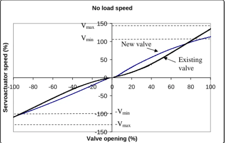
The mixability criterion is now checked with the new restriction diameter. Figure 8 shows the curves of the no load speed for the existing and new developed actuators. Speeds at the maximal opening agree in both extension and retraction modes (Vinf <Vmax< Vsup). However the
mixability criterion is not met since the difference of speed is greater than 10% of the lower limit of the maximal speed for ±40% of the valve opening. The maximal difference is 22% for 35% of opening in extension. No load speed -150 -100 -50 0 50 100 150 -100 -80 -60 -40 -20 0 20 40 60 80 100 Valve opening (%) S e rv o a c tu a to r s p e e d ( % )
Figure 8: No load speed without load of the existing actuator and of the new developed actuator It appears that a rectangular slot does not permit to meet the mixability specification. The speed curve of the existing actuator seems to indicate that the small openings correspond to a smaller slot width and that the maximal openings correspond to a larger slot width. Consequently, a slot design involving a width that varies with the opening will be investigated. A trapezoidal slot (Figure 9) is well adapted to have a small slot for small openings and a large slot width for maximal openings. The trapezoidal shape is chosen instead of the exact shape that would fit exactly the speed curves of the existing and new actuators for cost reasons. Indeed, as the slots are machined by electro-erosion, cutting an electrode with a trapezoidal shape is faster and easier than for a complex shape.
Trapezoidal slots
Supply pressure
Figure 9: Top view of the valve sleeve with trapezoidal slots Vmax Vmin New valve Existing valve -Vmin -Vmax
First, the equation of the valve section as a function of the opening has to be defined.
a b
X
α
h
δ
Figure 10: Notation for the computation of the slot section functions of the opening
According to the cross section of a trapeze with a small basis a, big basis δ and height X (Figure 10) is:
X a S 2 δ + = (10)
The valve section of a trapezoidal slot at maximal opening can be expressed as:
h b a S 2 max + = (11) Equation (10) becomes: X h a b X a S 2 2 + − = (12)
So the orifice functions of opening, is obtained from equations (11) and (12): X a h S h X a S − + = max (13)
Equation (13) shows that the orifice area only depends on the small basis a if the maximal stroke (h) and the section at maximal opening (Smax) are known. These two values are the same as for the rectangular slot.
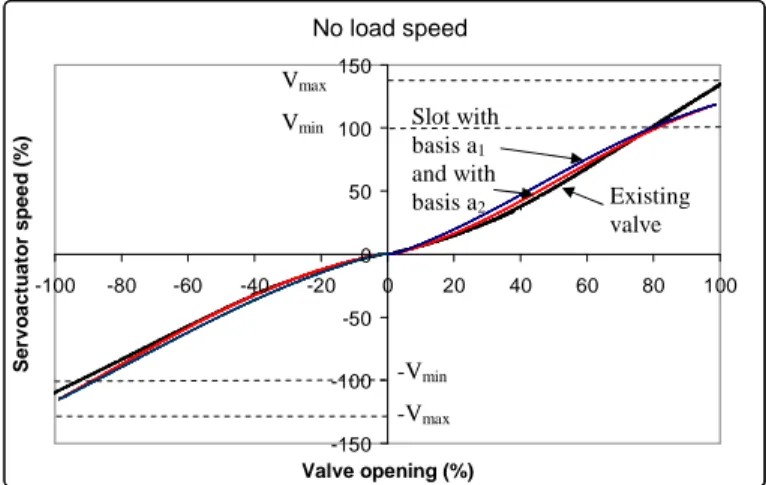
Two values of small basis for the trapezoidal slot are pointed out: a1 and a2 (see Figure 11). Simulations are run to compute the speeds without load of the servoactuator with trapezoidal slot for the two values of the small basis. These speeds are compared with the speed of the existing servoactuator (Figure 11). The value a1 corresponds to the speed curve the closest to the existing servoactuator speed curve. So it is better in a mixability point of view. However, the value a2 shows a
more linear behaviour than for a1, which makes the control easier. In addition the difference of speed with the existing actuator meets the specifications. The value a2 is thus selected for a control point of view.
Speed without load
-150 -100 -50 0 50 100 150 -100 -80 -60 -40 -20 0 20 40 60 80 100 Valve opening (%) S e rv o a c tu a to r s p e e d ( % )
Figure 11: Simulated no load speed curves for the existing actuator and for the new actuator with two
different basis of the valve trapezoidal slot
4.3 Validation
A second new valve with trapezoidal slots is manufactured and tested with the new restrictor diameter. The experimental results allow to compare the speed curve of the second new actuator (Figure 12) with the speed curve of the existing servoactuator. These results validate the design of the valve since the difference between the speeds is less than 7% of the lower limit of the maximal speed for ±40% of the valve opening.
No-load speed -150 -100 -50 0 50 100 150 -100 -80 -60 -40 -20 0 20 40 60 80 100 Valve opening (%) S e rv o a c tu a to r s p e e d ( % )
Figure 12: Measured speed curves for the existing servoactuator and for the new servoactuator with
trapezoidal slot Vmax
Vmin Slot with
basis a1 and with basis a2 Existing valve -Vmin -Vmax No load speed Existing valve New valve
5. Conclusion
This article has shown a design method for low-cost valves of redundant hydro-mechanical actuators. The two main requirements for the design are the speed gain curve and the maximal leakage flow rate. As these new valves aim at replacing old valves in existing actuators, another important requirement is the mixability of the new valves with the old ones. The design method lies on the equations of the speeds in extension and in retraction and of the maximal leakage flow rate. The pre-design has considered a common valve with sharp edges and rectangular orifice slots combined with a serial restrictor inserted on the supply line. After partial experimental validation, the proposed design process has pointed out the interest of using a trapezoidal slot in order to get the required speed gain over the whole valve opening range. The proposal is validated through the experimental measurement of the actuator no-load speed as a function of the valve opening.
REFERENCES
[1] Ellman, A., Virvalo, T., 1996, “Formation of Pressure Gain in Hydraulic Servovalves and its Significance in System Behavior”, Fluid Power Systems and Technology, ASME FPST-Vol. 3, November, pp. 77–81, Atlanta, GA. [2] Merritt, H.E., 1967, “Hydraulic Control Systems, John
Wiley & Sons”, New York, New York
[3] Lewis,C.W., “Some Factors Influencing the Speed of Response of Hydraulic Position Servomechanisms”, Aeronautical research council reports and memoranda, 1958
[4] Mare, J-C., Attar B., 2008, “Enhanced model of four ways servovalves characteristics and its validation at low temperature”, International Journal of Fluid Power, Vol 9 N°2, pp 35-43, ISSN 1439-9776
[5] Faisandier, J., 2006, Mécanismes Hydrauliques et Pneumatiques, 9°ed. Paris. Dunod.
[6] Thayer, W.J., 1962, “Specification standards for electrohydraulic flow control servovalves, Technical bulletin 117, Moog.
[7] Baz A., Barakat A., Rabie G., “Effect of radial clearances in hydraulic spool valves on the static and dynamic characteirstic of servomechanism”, Proceedings of the 5th world congress on Theory of Machines and Mechanims, ASME, 1979, pp 785-788
[8] Eryilmaz, B., Wilson, B.H., 2000, “Modeling the Internal Leakage of Hydraulic Servovalves”, International
Mechanical Engineering Congress and Exposition, ASME, Vol. DSC-69.1, pp. 337-343, Orlando, USA.