HAL Id: tel-01767745
https://pastel.archives-ouvertes.fr/tel-01767745
Submitted on 16 Apr 2018HAL is a multi-disciplinary open access archive for the deposit and dissemination of sci-entific research documents, whether they are pub-lished or not. The documents may come from teaching and research institutions in France or abroad, or from public or private research centers.
L’archive ouverte pluridisciplinaire HAL, est destinée au dépôt et à la diffusion de documents scientifiques de niveau recherche, publiés ou non, émanant des établissements d’enseignement et de recherche français ou étrangers, des laboratoires publics ou privés.
Particle acceleration with beam driven wakefield
Antoine Doche
To cite this version:
Antoine Doche. Particle acceleration with beam driven wakefield. Plasma Physics [physics.plasm-ph]. Université Paris Saclay (COmUE), 2018. English. �NNT : 2018SACLX023�. �tel-01767745�
Particle acceleration with beam
driven plasma wakefield
Thèse de doctorat de l'Université Paris-Saclay préparée à l’école Polytechnique École doctorale n°572 : ondes et matières (EDOM) Spécialité de doctorat: optique et physique des plasmas
Thèse présentée et soutenue à Palaiseau, le 09 Mars 2018, par Antoine DOCHE
Composition du Jury :
M. Patrick MORA, Directeur de recherche
CPhT, école Polytechnique - CNRS Président du jury
M. Philippe BALCOU, Directeur de recherche
CELIA, CEA – CNRS – Université de Bordeaux Rapporteur
M. Emmanuel D’HUMIERES, Directeur de recherche
CELIA, CEA – CNRS – Université de Bordeaux Rapporteur
Mme. Edda GSCHWENDTNER, Directrice de recherche
CERN, Engineering Department Examinatrice
M. Sébastien CORDE, Maitre de conférence
LOA, École Polytechnique Co-directeur de thèse
M. Victor MALKA, Directeur de recherche
LOA, École Polytechnique Directeur de thèse
NNT : 2 0 1 8 SAC L X 0 2 3
Remerciements - Acknowledgements
Avant toute chose, il faut préciser que différents acteurs ont rendu possible les campagnes expérimentales sur lesquelles repose ce travail et la rédaction de ce manuscrit. Eux seuls méritent tous les honneurs qui découlent des accomplissements scientifiques présentés dans ce texte, et pour leur temps, leur aide et leur confiance je tiens à les remercier individuellement.
Je souhaite remercier en tout premier lieu mon directeur de thèse, Victor Malka pour son accueil au Laboratoire d’Optique Appliquée dès février 2014. C’est grâce à lui que ce manuscrit a pu être écrit, grâce à son soutien face aux difficultés, et à ses conseils quant à la direction à prendre à chaque moment important. J’exprime donc beaucoup de reconnaissance pour ses enseignements scientifiques et humains, pour toutes les opportunités qu’il a rendues possibles, notamment pour partir étudier sous d’autres horizons.
Je remercie à présent vivement Sébastien Corde, mon co-encadrant de thèse depuis Août 2015. Le difficile parcours scientifique qu’a constitué cette thèse n’a été possible que grâce à son intervention. Je souhaite exprimer mes remerciements pour la patiente infinie dont il a fait preuve, ses efforts incessants de pédagogie, son enthousiasme pour les discussions scientifiques et son sens inné du partage. Outre l’opportunité qu’il m’a offerte de partir découvrir la recherche scientifique outre-Atlantique, il restera un modèle de précision scientifique et plus largement de rigueur intellectuelle dans le travail. Il a sans aucun doute redonné de l’enthousiasme à cette thèse, et pour son action auprès des étudiants et de ces collègues il mérite plus largement toute la reconnaissance et l’estime des membres du laboratoire dans lequel cette thèse a eu lieu. L’expérience d’accélération d’un paquet distinct de positron dans un accélérateur par onde de sillage plasma est avant tout la récompense du travail de la collaboration E200 au sein de la plateforme FACET, au SLAC. Pour cela je tiens à remercier les différentes personnes qui ont rendu cette expérience possible, qui m’ont transmis d’innombrables savoir-faire, en même temps que beaucoup de nouveaux concepts scientifiques. Merci avant tout à Michael « Mike » Litos pour sa bonne humeur, sa passion communicative pour la physique et son enseignement dispensé avec patience. Merci à Spencer Gessner qui restera un modèle, par son efficacité dans le travail et sa passion pour les sciences. Merci à Mark Hogan pour son soutien bienveillant au cours des expériences, très important dans les moments de doute. Merci également au Professeur Chan Joshi pour ses conseils, remarques et enseignements, il oriente avec brio la collaboration E200, sa bienveillance et son influence sont une chance pour tous les étudiants. Merci à tous les gens qui ont partagé leur savoir sans compter, m’ont spontanément aidé à faire face aux imprévus divers : Carl Lindstrøm qui comme moi se bat pour défendre une thèse, Brendan O’Shea pour son aide face à l’inextricable système informatique de FACET, Kenneth « Ken » Marsh pour avoir partagé sans compter son savoir-faire expérimental, Christine Clarke et Selina Green pour leur disponibilité et leur soutien logistique quelle que soit l’heure du jour ou de la nuit. Je voudrais remercier également Christopher « Chris » Clayton pour sa motivation
Remerciements communicative pendant les runs, ses discussions fort intéressantes pendant les pauses, Navid Vafaei pour son soutien moral quand les résultats tardaient à arriver… Merci à Chris Beekman pour les bons moments passés en Californie comme en France au cours de ce travail intensif. Merci à Erik Adli pour ses enseignements, son invitation à Oslo également, et merci à James Allen et Rafal Zgadzaj pour leur amitié, et pour le temps passé à travailler dans la bonne humeur. Merci à tous les autres personnels du SLAC qui ont rendu ce travail possible.
L’essentiel du travail présenté ici a été accompli grâce à l’héritage scientifique et au personnel du Laboratoire d’Optique Appliquée. Pour cela, des remerciements appuyés doivent être adressés aux différents membres de groupes de recherche FLEX et SPL. Merci à Alessandro Flacco, qui a co-encadré mon travail de thèse pendant les 8-10 premiers mois, son habileté technique et son sens physique ont été une source d’inspiration pendant l’ensemble de ces trois années. Merci à Julien Gautier, Amar Tafzi, Jean-Philippe Godet, Jean-Philippe Rousseau, Stéphane Sebban, Fabien Tissandier, Antoine Rousse, Davide Boschetto, Benoit Mahieu, Guillaume Lambert, Agustin Lifschitz, Pascal Rousseau, Boris Vodungbo et Cédric Thaury, pour leur bonne humeur, leurs conseils et leur aide. Merci à Jean-Marcel Rax pour toutes les discussions passées ensembles, et toutes les questions générales de physique au sujet desquelles il a pu éclairer le groupe des étudiants. Mille mercis aux gars de la mécanique, Jean-lou « Charly » Charles, Mickaël Martinez, Bernard Allali et Florian Oper. Merci également au personnel du secrétariat pour leur soutien, leur disponibilité et leur bonne humeur : Sandrine Tricaud, Octavie Verdun, Lucie Huguet, Catherine Buljore, Patricia Toullier, merci.
Pendant trois années au LOA, j’ai pu côtoyer d’autres étudiants, des camarades d’infortune que je n’oublierai pas. Merci donc à Dan Lévy, Viacheslav Smartsev, Adrien Despresseux, Safir Lazar, Antonin Siciak, Carla Da Silva Alves, Francesco Massimo, Olivier Delmas, Florian Mollica, Gaël Massé, Emilie Bayart, Evgeny Chelnokov, Igor Andriyash, Julien Ferri, Hermine Danvy, Flavien Museur, Chris Beekman, Benjamin Vauzour, Clément Caizergues, Emilien Guillaume, Andreas Döpp et Marc. Pour tous les moments passés ensemble à travailler, discuter, s’amuser, merci beaucoup, ce fut une belle aventure.
Par ailleurs, beaucoup d’autres personnes méritent des remerciements. Merci beaucoup à Nicolas Panel, Joris Guery, Pierre Chopin, Olga Chashchina et Raphael Deswartes, un remerciement également de la part de tous les étudiants du campus de l’École polytechnique pour le temps qu’ils leur ont consacré. Merci à Benjamin Madon et Pascal Delange pour leur amitié. Merci à mes parents et à ma sœur, ainsi qu’aux autres membres de ma famille proche. Ce manuscrit est dédié à la mémoire de Loys et Laurent Doche, qui auraient bien aimé découvrir son sujet. Merci beaucoup à Liu Jia pour son soutien et sa compréhension face au chronophage travail que constitue la rédaction d’un manuscrit de thèse. Merci à tous mes amis du campus de Polytechnique, Shen Yixin, Weiran Zhang, Lei Yu, Lawrence Das Sourav, Guilhem Beaussoleil, François Deloche et tous les autres.
Contents ... vi
Introduction ... 1
PART I
Chapter 1 1. Particle accelerators: technology and applications ... 7a. A century long history ... 7
b. Particle beams and applications ... 9
2. Laser physics concepts and formalism ... 11
a. Laser fields and Gaussian pulses ... 11
b. Relativistic regime ... 13
c. Maxwell equations ... 14
d. Chirped pulse amplification ... 14
3. Beam physics concepts and formalism ... 15
a. Emittance ... 16
b. Transfer matrices and beam transport ... 17
c. Twiss parameters and beam envelope equation ... 18
d. Evolution of the trace-space ellipse in free space ... 19
e. Periodic focusing systems ... 20
f. Sources of emittance growth ... 21
Chapter 2 1. Plasmas ... 23
a. Electronic plasma frequency ... 23
b. Debye length ... 24
2. Ionization ... 25
a. Low-Field Ionization ... 25
b. Multi-Photon Ionization ... 25
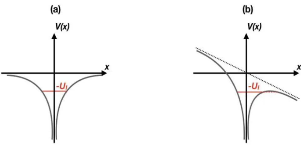
c. Tunnel Ionization and Barrier Suppression Ionization ... 26
Contents
4. Electromagnetic waves in plasmas ... 29
Chapter 3 1. Propagation of the driver in a plasma ... 32
a. Laser pulses propagation in a plasma ... 32
b. Electron beams propagation in a plasma ... 33
2. Solution of plasma wave excitation in the linear regime ... 35
a. Plasma wave excitation ... 35
b. Beam driven plasma electron density waves ... 37
c. Laser driven plasma electron density waves ... 43
3. One-dimensional solution of plasma wave excitation in the nonlinear regime ... 45
4. Nonlinear “Blow-out” regime ... 46
a. The bubble regime ... 46
b. Wavebreaking limit ... 47
PART II
Chapter 4 1. Positron driven plasma wakefields ... 522. Positron acceleration experiments ... 53
3. SLAC and FACET Facilities ... 54
a. Accelerator facility ... 54
b. Beams and parameters ... 55
c. Plasma source ... 57
d. FACET laser systems ... 58
Chapter 5 1. Experimental setup and diagnostics ... 61
a. Experimental setup ... 61
b. Energy Spectrometer ... 64
c. EOS longitudinal diagnostic ... 65
d. Beam charge diagnostics ... 66
f. Simulations ... 67
2. Acceleration of a trailing positron bunch ... 68
a. Proof of acceleration ... 68
b. Beam loading, theory and experimental observation ... 70
3. Acceleration regime ... 75
a. Emittance manipulation system ... 75
b. Nonlinear to quasilinear positron driven waves ... 76
PART III
Chapter 6 1. Acceleration, trapping and injection of particles in plasma wakefield ... 84a. Phase velocity of plasma density waves ... 84
b. Acceleration, trapping and LWFA phase detuning ... 84
c. Injection techniques ... 87
2. Salle Jaune facility ... 90
a. Facility ... 90
b. Energy spectrometer ... 91
c. Side-view interferometer ... 93
3. Hybrid LWFA-PWFA experiment and results ... 95
a. Experimental setup ... 95
b. Effect of the second gas jet on the electron beam ... 95
c. Effect of the foil on the electron beam ... 99
Chapter 7 1. Betatron X-ray radiation in LWFA experiments ... 105
a. Radiation from charged particles ... 105
b. Radiation in LWFA experiments ... 107
2. Design and numerical characterization of a two-stage hybrid LWFA-PWFA X-ray source ... 109
a. Motivations for a decoupled scheme ... 109
b. Numerical results ... 111
Contents
Conclusion ... 116
Bibliography ... 120
Context
Particle accelerators have tremendous impact in academic research together with many important societal applications for example for cancer treatments. In the context of fundamental research, they have been built to probe materials and to study fundamental interactions by colliding beams of energetic particles with extreme luminosity. For this purpose, particle beams (also named particle bunches in this manuscript) can reach a speed close to c, the speed of light. More compact machines, that deliver lower energy particle beams became indispensable for several activities in our modern societies, they even contribute to fight cancer and save lives by providing particular ionizing radiations to treat tumors.
The current accelerators in use are said to be radiofrequency accelerators, as the particle beams are moving in cavities in which devices called klystrons produce the electromagnetic wave that the particles “surf” to gain energy. A fundamental limitation, the electric breakdown, occurs when the field in the electromagnetic cavity becomes too high. When the maximum admissible electric field is reached, the metallic cavity can be destroyed. As a consequence of this limited value of the electric field of the order of 100 MV/m, scientists have to build longer and larger facilities to increase the final energy of the particle beams. For fundamental research, progresses in theoretical models require always higher energy beams, that is why a new technology is now needed, to provide a sustainable alternative to the limitations of “conventional” accelerators.
Figure 0.1: (a) A conventional accelerator: SLAC National Accelerator facility. The total length of the linear accelerator is 3 km. (b) An experimental platform dedicated to LWFA: Salle Jaune at Laboratoire d’Optique Appliquée, Palaiseau France, the length of each room is typically 30 m.
Introduction
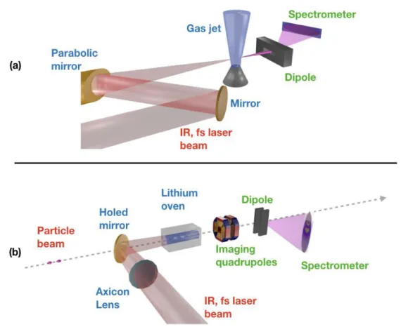
Plasmas as they are ionized media, are not limited by electrical breakdown, which explains why this medium has been investigated as an alternative to metallic cavities. By controlling the collective motion of electrons with lasers, accelerating fields of the order of hundreds of GeV/m have been demonstrated [Malka 02]. Such high gradients are more than three orders of magnitude higher than the best accelerating gradient of conventional facilities. The difference in sizes between conventional and plasma-based accelerators can be seen in Fig. 0.1: although the specific experiment (b) does not provide particles of GeV energy yet as the massive SLAC facility (a) does, conventional and plasma-based accelerators typically have this size ratio. Among the four plasma-based schemes [Joshi 03], my thesis will deal with two of them: Laser Wakefield Acceleration (LWFA) [Tajima 79] and Plasma Wakefield Acceleration (PWFA) [Fainberg 56, Chen 85]. In these two concepts, an electron density wave is excited in a plasma. The wave driver – either a laser pulse (LWFA, Fig. 0.2 (a)) or a bunch of particles (PWFA, Fig. 0.2 (b)) - deposits energy in the medium as it excites the wave. The accelerated beam extracts this energy.
Both the LWFA and the PWFA schemes have focused the attention of the scientific community, and many breakthrough results were theoretically and experimentally achieved. Plasma-based acceleration techniques started with the precursor article by Tajima and Dawson [Tajima 79]. Four schemes were suggested, of whom PWFA and LWFA have bright prospects. The PWFA scheme was built theoretically [Ruth 85, Katsouleas 86] before the first experimental demonstrations for electrons [Rosenzweig 88, 89, Blumenfeld 07, Litos 14] and positrons [Blue 03, Corde 15] drive beams. The LWFA acceleration scheme allows the excitation of an intense plasma wave by a laser pulse of a few joules and a few
Figure 0.2: (a) A typical laser wakefield experiment, a parabolic mirror focuses a laser beam into a gas jet. The emerging electron beam is characterized by a spectrometer. (b) A plasma
tens of femtoseconds. This is why this scheme can be accomplished in limited size and low cost facilities such as the Salle Jaune at Laboratoire d’Optique Appliquée (Fig. 0.1 (b)). The first experimental demonstration of quasi-monoenergetic electron beam generation in LWFA was accomplished in 2004 [Mangles 04, Faure 04, Geddes 04], before further improvement of the beam properties was made [Faure 06]. Multi-GeV electron acceleration was recently reached with modern pettawatt laser technologies [Kim 13, Leemans 14, Wang 13]. LWFA and PWFA rely on the transfer of energy to a beam of particles, thanks to plasma electron density waves. The driver energy deposition in the plasma is therefore the first physical phenomenon that needs to be understood and optimized to build a plasma-based accelerator. Apart from plasma electron density waves driving, another major challenge occupies most of the research community: the injection of particles into the accelerating cavity to extract its energy. In fact, the energy contained in the excited wave can either be sampled by some particles in the beam driving the wake itself, or from a second, externally produced beam, or else by electrons from the plasma [Joshi 03].
LWFA and PWFA scientific communities past experiments have already set up many milestones in the production of high quality, high-energy particle bunches. These two schemes already led to multi-GeV particle bunches, with a very high quality: low divergence, high brightness and low energy spread of the particle beams. Therefore, some medical and industrial non-destructive imaging applications can already be considered with the beam quality plasma-based facilities provide. Moreover, plasma accelerators open very promising prospects towards compact and very high-energy colliders. This last application that is extremely challenging requires many improvements of the beam properties and to overcome several technological limitations. First, the challenge of staging PWFA or LWFA accelerators is to be solved, second, beam quality has to be preserved when wakefields are used to “boost” externally produced particle beams. Last, the total accelerated charge should be increased further.
Objective of this thesis
As demonstrated in the previous paragraph, hopes lie on plasma-based acceleration experiments towards the realization of compact and cost-efficient electron-positron colliders. This is true even if several technological challenges still require to be overcome before such a facility is built. Regarding the staging of plasma modules, accelerator stages would be used to further accelerate a distinct bunch of particles, independently of the accelerating cavity generation. This requires to master a scheme in which a distinct bunch of particles extracts energy from a plasma accelerating cavity. This was accomplished already with electrons [Litos 14], but is yet to be demonstrated with positrons. The important milestone of accelerating a distinct bunch of positrons independently of the technique employed to drive the plasma accelerating cavity will be the prime objective of my thesis.
Moreover, beam driven plasma wakes experiments still require huge conventional facilities to take place: at SLAC for instance, FACET plasma wakefield experiments use the 20.35 GeV electron or positron beams accelerated by the radiofrequency facility to drive plasma waves. This is a serious limitation to the number of experiments that can simultaneously take place in the world. In the long run, it is a limitation to scientific progresses accomplished by the community of researchers. The second part of my thesis will therefore be dedicated to the realization of a hybrid LWFA-PWFA scheme at the Laboratoire d’Optique Appliquée in Palaiseau, France. This experiment is expected to demonstrate that plasma waves can be
Introduction
driven in a gas jet, using a LWFA-produced electron beam. Obtaining a clear evidence of the excitation of an accelerating cavity in this hybrid setup is the second objective of the work presented here. In addition, manipulating LWFA produced electron beams in optics laboratories was driven by the interest for x-ray Betatron sources. The hybrid scheme introduced above opens prospects regarding the optimization of such x-ray sources. That is why we will study x-ray light emission as well in this second experiment.
Outline of the manuscript
Part I provides first a brief presentation of the history of particle accelerators and of their applications in Chapter 1. Second, useful concepts in laser and beam physics are introduced in both Chapter 1 and Chapter 2. In Chapter 3, theoretical details are given about LWFA and PWFA. The driving of plasma waves by a particle beam or a laser pulse is derived in detail in the “linear” regime case and some qualitative details about the “nonlinear” or “blow-out” regime are provided. In addition, a comprehensive description of the propagation of a laser pulse and of an electron bunch in a plasma is made.
Part II is dedicated to the main experimental result, the demonstration of the acceleration of a trailing positron bunch in a plasma wakefield accelerator. Chapter 4 and Chapter 5 introduce the experimental setup of the experiment that took place at the FACET (Facility for Advanced aCcelerator Experimental Tests) facility at SLAC National Accelerator Laboratory. The different experimental diagnostics and methods are then described in further details.
Chapter 5 reports the results of the experiment and the simulations performed to obtain further insight into the acceleration process underlying this experimental achievement. Part II is concluded by a study of the wakefield regime driven in the plasma during the experiment. Part III presents the hybrid LWFA-PWFA experiments accomplished at Laboratoire d’Optique Appliquée. Chapter 6 is dedicated to the experimental campaign of 2017 in which a LWFA-produced electron beam was used to drive plasma waves in a gas jet. In this experimental study, an electron beam created by laser-plasma interaction is refocused by particle bunch-plasma interaction in a second gas jet. A study of some physical phenomena associated to this hybrid LWFA-PWFA platform is then accomplished. Chapter 7 reports the work accomplished in 2016 to exploit the hybrid LWFA-PWFA scheme in order to enhance the X-ray emission produced by the LWFA electron beam. The first experimental realization of this last scheme is reported, and its promising results are discussed.
Chapter 1. Particle accelerators, laser and beam physics
Particle accelerators, laser and beam physics
This introductory chapter begins with a short history of particle accelerators. First is a chronological presentation of particle accelerator facilities and their corresponding applications. The second and third sections of this chapter provide a brief introduction to laser and beam physics, by introducing the main concepts of these fields that will be used throughout the manuscript. These sections introduce the formalism and the conventions used in the rest of the text as well.
Contents
1. Particle accelerators: technology and applications ... 7
a. A century long history ... 7
b. Particle beams and applications ... 9
2. Laser physics concepts and formalism ... 11
a. Laser fields and Gaussian pulses ... 11
b. Relativistic regime ... 13
c. Maxwell equations ... 14
d. Chirped pulse amplification ... 14
3. Beam physics concepts and formalism ... 15
a. Emittance ... 16
b. Transfer matrices and beam transport ... 17
c. Twiss parameters and beam envelope equation ... 18
d. Evolution of the trace-space ellipse in free space ... 19
e. Periodic focusing systems ... 20
f. Sources of emittance growth ... 21
1. Particle accelerators: technology and applications
a. A century-long historyAccelerators and particle colliders have a long history made of many successive innovations; new facilities emerged all along the 20th century. Several particle acceleration schemes were
used, however only two of them are still in use in world-class facilities.
The very first accelerators were electrostatic ones, such as the Van de Graaff accelerator invented in the late 1920s [Van de Graaf 33]. These machines were using a static electric field set up between two electrodes to accelerate electrons. However, electrostatic accelerators were strongly limited by electrical breakdown that could easily destroy the setup; the maximal energy that the particles could reach was limited to 20-30 MeV [Humphries 02]. Starting from the 1930s, accelerators become radio-frequency (RF) electromagnetic machines. Although they are called radio-frequency accelerators, most of these devices work with microwave electromagnetic fields. Guiding cavities sustain the oscillations of an electromagnetic wave with a wavelength ranging from a few centimeters to a few tens of centimeters and a phase velocity close to the velocity of the accelerated particles. Particle energies were then pushed higher thanks to the invention of a circular acceleration scheme: cyclotrons that would produce electron or proton beams from the 1930s on. [Lawrence 32] These circular facilities force accelerated particles to circle several times in an electromagnetic field before exiting the device. Cyclotrons were using magnetic fields to force the particles to move on two half-circle orbits and were accelerating them in between where the particles would see an electric field. Increasing slowly their energy each time they circle through the machine, the particles would rotate at a radius that becomes larger and larger until they escape from the ring. Particle energies in these machines were limited to a few tens of MeV at first, until a new generation of circular accelerators was invented: synchrocyclotrons. Facilities of this generation, some of whom are still being built nowadays, accelerate individual bunches of particles only, and match the radio-frequency electromagnetic field frequency with the bunches energy. This strategy needs the magnetic field amplitude to compensate for the energy gain by bending accordingly more the particles trajectories, leading to more turns inside the accelerator ring and therefore to particles with a higher final energy. This technology is still common for proton medical accelerators, as it is
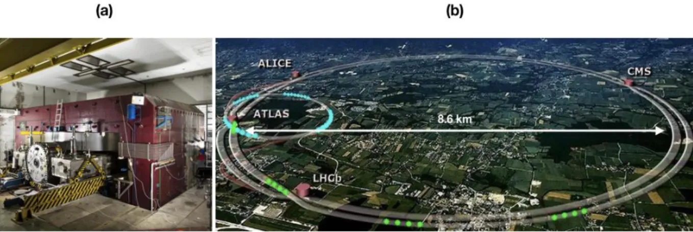
Figure 1.1: (a) CERN 1956 synchrocyclotron producing bunches of protons with an energy of 600 MeV. (b) The Large Hadron Collider facility nowadays, that can provide 7 TeV particles. As displayed on the figure, the main ring has a diameter of 8.6 km. From CERN.
Chapter 1. Particle accelerators, laser and beam physics
an efficient and repeatable way to produce proton bunches of 70 to 250 MeV for instance. An example of one of the first synchrocyclotron ever built can be seen in Fig. 1.1 (a). A modern facility used for proton therapy is displayed in Fig. 1.3 (a). This last picture is the treatment room of Orsay proton therapy center, a facility which relies on a synchrocyclotron to produce the ionizing radiations. The main technology for fundamental physics accelerators is the synchrotron [Veksler 44], used for instance at the Large Electron-Positron Collider from 1989 to 2000 [Myers 90] and at the Large Hadron Collider (LHC, Fig. 1.1 (b)) until now. Synchrotrons are modified cyclotrons in which the magnetic field amplitude increases with the increasing particle energy so that the particles can maintain their orbit inside the circular accelerator and reach very high energies. The LHC accelerates protons up to 7 TeV, the highest particle energy value ever obtained in an experiment; it led to the discovery of the Higgs boson [LHC 12].
Although circular facilities flourished around the world, driven by their multiple applications, linear accelerators were not abandoned. Indeed, the energy lost by synchrotron radiation in circular accelerators, makes their uses for high-energy (greater than hundreds of GeV) electron-positron colliders non-relevant. Only linear acceleration prevents such loses. With accelerating fields limited by the electric breakdown, the size of these facilities has to become higher and higher to reach high energies. Two different linear RF based accelerator technologies exist. Linear induction accelerators were invented in the early 1960s, and were using a phenomenon called induction isolation to maintain the potential differences in the facilities low, while the net electric potential on the axis of the beam line would efficiently accelerate particles [Christophilos 64]. Linear induction accelerators were not the first devices to use magnetic induction to transmit energies to particles. The Betatron, a circular accelerator invented in 1935 was already inductively accelerating particles in a torus shaped vacuum chamber. The most widespread kind of linear accelerators are the electromagnetic radio-frequency accelerators, based on a scheme that was suggested as early as 1924 [Ising 24]. Stanford Linear Accelerator (SLAC National Accelerator Laboratory) for instance is such an accelerator, and opened in 1966 [Neal 68]. It led three of its users to obtain a Nobel Prize, in 1976 for the discovery of the charm quark, in 1990 for the quark structure and in 1995 for the discovery of the tau lepton. Successive upgrades led SLAC accelerator energy to increase twice in its history. Two major linear accelerator facilities have been proposed for the next decades. The International Linear Collider (ILC) first, whose particles will reach the energy of 250 𝐺𝑒𝑉 and which may be built in Japan [ILC 07]. Its footprint is estimated to be 30 km. Another major project is the Compact Linear International Collider (CLIC), which is to accelerate particles to the energy of 1.5 𝑇𝑒𝑉 [CLIC 12].
Accelerator Technology Date Particles Energy
Van De Graaf acc. Electrostatic 1929 𝑒− 25 𝑀𝑒𝑉
Betatron acc. Induction 1935 𝑒− 300 𝑀𝑒𝑉
Linear Induction acc. Induction 1962 𝑒− 50 𝑀𝑒𝑉
SLAC Linear RF 1966 𝑒−/𝑒+ 50 𝐺𝑒𝑉
LEP Circular RF 1989 𝑒−/𝑒+ 25 − 105 𝐺𝑒𝑉
LHC Circular RF 2008 𝑝 7 𝑇𝑒𝑉
ILC Linear RF - 𝑒−/𝑒+ 250 𝐺𝑒𝑉
CLIC Linear RF - 𝑒−/𝑒+ 1.5 𝑇𝑒𝑉
In Fig. 1.2 are summarized the different accelerators discussed in the previous paragraph along with their energy. The three first accelerators describe a general kind of devices, in contrast with the last five that are unique world-class facilities or proposed colliders. As can be seen, linear induction accelerators did not increase the maximal energy reached by particle bunches, however, they were able to produce the highest current bunches at the time they were invented. Large scale facilities, involving many countries and built in the late 20th and
21st century (LEP, LHC, ILC and CLIC) reach much higher energies than their predecessors.
b. Particle beams and applications
Accelerator facilities are built for different purposes: they are used either for fundamental research, medical or industrial uses.
With an annual market of few billions of euros with an annual increase of about 10%, the accelerators industry is a very flourishing activity. These applications concern cancer therapy, ion implementation, electron cutting and welding, electron beam and X rays irradiators, radio-isotope production, ion beam analysis, neutron generators, to cite the more important. In medicine, the effects of radiations on human bodies were discovered at the end of the 19th
and at the beginning of the 20th century, along with the interest cancer research had for
ionizing radiations [Pusey 00]. The first era of radiation medicine considered only using gamma-rays, emitted by natural radioactive elements or by x-ray tubes. The discovery of the nuclear reactor made the production of artificial radioactive isotopes easier and boosted x-ray therapy development. However, from the early 1900s to the 1940s therapists were still fumbling on the use of radiations [Coutard 37]. X-ray therapies are now quite common to treat most kind of cancers, even if the defects of this technology fueled scientific research about other kinds of radiations: particle beams. Particle therapy started during World War II and is still widely used nowadays [Thwaites 06]. Electron therapy has been considered [Klein 08], but proton therapy seems more promising [Levin 05]. Facilities such as the synchrocyclotron of Orsay, France (Fig. 1.3 (a) and (b)) perform proton therapy. Hadrontherapy appears to be more interesting than classical x-ray therapy because the later has side effects such as provoking burns, and revealed itself to be less effective in several situations. The high costs and large footprints of particle therapy facilities fuel the need for
Figure 1.3: (a) Gantry of the proton therapy center in Orsay, France. The patient lies on the bed (center), the ionizing radiations flow from the mobile green and white device (left). (b) Moving structure of the gantry. The chamber (a) is inside the circular shape on the top left. The grey device on the bottom of the picture is one of the brake of the moving structure. Its
Chapter 1. Particle accelerators, laser and beam physics
new particle sources. Plasma-based acceleration techniques appear to be promising solutions on that point of view [Malka 08]. Both radiobiology experiments [Pommarel 17] and simulations (as in Fig. 1.4 (a)) to optimize treatments are carried out from plasma-based particle beams.
Particle colliders are also the primary experimental apparatus of fundamental physics research. To study the fine structure of matter, researchers need to collide particles with higher and higher energies in order to study smaller and smaller subdivisions of their constituents. The LHC for instance is a 27 km in circumference torus shaped facility that accelerates protons to 7 𝑇𝑒𝑉 and led to the discovery of the Higgs boson [LHC 12]. The colossal footprint of the LHC can be seen in Fig. 1.1 (b). Its total cost is estimated to be of about 10 billion euros, which makes it one of the most expensive scientific machines ever built. Future colliders listed in Fig. 1.2 are also expected to operate with particle energies exceeding the 𝑇𝑒𝑉, and therefore their sizes will grow accordingly: the ILC is expected to measure 30 𝑘𝑚 [ILC 07]. The cost and footprint of modern facilities also suggest that a new kind of technology should be considered to accelerate more efficiently particle beams. CERN director Fabiola Gianotti emphasized the challenge for the scientific community: “High-energy accelerators have been our most powerful tools of exploration in particle physics, so we cannot abandon them. What we have to do is push the research and development in accelerator technology, so that we will be able to reach higher energy with compact accelerators” [Gibney 15]. Plasma-based accelerators also appear to be very promising on that point of view: the size of the future conventional ILC facility is correlated with the maximal accelerating field achievable due to electrical breakdown limit, 100 𝑀𝑉/𝑚 . Plasma-based acceleration offers three orders of magnitude higher accelerating fields: 100 𝐺𝑉/𝑚 can be achieved [Malka 02]. Although accelerator physicists still face many challenges, a plasma-based facility design has already been considered [Adli 13].
Laser-plasma accelerators should contribute in the near future to medical and security particle beams applications. For security purpose, LWFA bremsstrahlung gamma-ray beams, that allow non-destructive inspection with a high spatial resolution, could become prime tools of nuclear facilities or astronautic companies. Indeed, actors from these fields need
non-Figure 1.4: Examples of applications of particle beams, some of which can already be accomplished with plasma-based particle accelerators. (a) Simulation of an electron beam dose deposition for cancer treatment. Research is being done on the use of the different kinds of particles, here electron beams burn also the body (blue and green areas) around the tumor (red area). (b) Gamma-ray internal imaging of a metallic sample accomplished at LOA. From
destructive testing techniques to study material fatigue, to ensure safety and to perform quality control [Cartz 95]. SourceLab, a start-up, spin-off of LOA for instance is developing such sources to identify cracks spreading on materials. For the application of non-destructive testing, plasma-based acceleration could provide a cheaper and more efficient solution for all users [Malka 08]. Betatron X-ray beam delivered by LWFA is another pertinent source for imaging application. The spatial coherence and the small dimension of the source allow to perform phase contrast X-ray imaging of biological object with a resolution of tens of micrometer [Corde 13]. This opens the possibility to detect breast cancer tumor at earlier stage with a moderate dose deposition. Direct use of very high energy electrons (in the 100 to 300 MeV) is envisaged for cancer treatments. It was shown that in the case of prostate cancer, this approach should reduce by 20% the dose delivered in safe tissues and sensitive organs compared to the dose deposited by X-MRT (modulated photon radiotherapy). These near-term applications are illustrated in Fig. 1.4.
2. Laser physics concepts and formalism
LWFA and PWFA both rely on concepts of plasma and laser physics. This section and the next introduce the formalism and the conventions used in these two fields of physics that will be used in the whole manuscript.
a. Laser fields and Gaussian pulses
Gaussian beams are preeminent in physics. In fact, Gaussian beams are laser fields solution of the Helmholtz equation, under the hypothesis of the paraxial approximation. Gaussian beams describe therefore the behaviour of a laser field propagating through an isotropic medium under the paraxial approximation. This is the realistic solution (as opposed for instance to the plane wave description, simpler but unrealistic) of the equation that describes accurately the beams scientists use in their experiments. In the rest of the manuscript, when an explicit form is needed for the laser field used in the experiments, we will consider a Gaussian beam.
For a Gaussian electromagnetic pulse the complex vector potential reads: 𝑨(𝑟, 𝑧, 𝑡) = 𝐴0 𝑤0 𝑤(𝑧)𝑒 −𝑤(𝑧)2𝑟2 𝑒−2 ln(2) (𝑐𝑡−𝑧)2 𝑐2𝜏02 𝑒𝑖𝜔𝑡𝑒−𝑖(𝑘𝑧+ 𝑘𝑟2 2𝑅(𝑧) −𝜓(𝑧))𝒖 (1.1) Where the parameters are the following:
𝜔 is the angular frequency of the laser pulse. 𝑘 = 2𝜋𝜆 is the wave vector of the laser pulse. 𝑤0 is the waist dimension of the laser pulse. 𝑧 is the algebraic distance to the beam focal spot. 𝜓(𝑧) = arctan (𝑧𝑧
𝑅) is the Gouy phase, an additional phase term that contributes to shift
the phase near the focal spot, but that is constant far from it. This term is responsible for the 𝜋-phase shift at focus.
Chapter 1. Particle accelerators, laser and beam physics
𝑐𝜏0 is the laser pulse length in vacuum, measured as the Full Width at Half Maximum of the beam in the propagation direction 𝑧.
𝑘𝑟2
2𝑅(𝑧) where 𝑅(𝑧) = 𝑧 (1 + 𝑧𝑅2
𝑧2) is the curvature radius. This is an additional quadratic
term that takes into account the curvature of the phase front at distance 𝑧 from the focal spot.
𝑤(𝑧) = 𝑤0√1 +𝑧
2
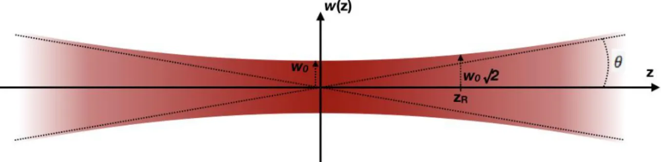
𝑧𝑅2 is the transverse size of the laser pulse. The graph (𝑧, 𝑤(𝑧)) is
ploted in Fig. 1.5, where the asymptotic evolution of the waist dimension appears clearly.
Formula (1.1) describes a laser pulse that has a Gaussian shape in the 𝑧 direction, whose envelope is given by the term 𝑒−2 ln(2)
(𝑐𝑡−𝑧)2
𝑐2𝜏02 . The 𝑧 direction is also the direction of
propagation in the formula written above. The pulse has a Gaussian shape in the transverse direction, given by the term 𝑒−𝑤(𝑧)2𝑟2 .
In the LWFA experiments described in this manuscript, the laser final focus is often accomplished with a parabolic mirror that focuses an initially well-collimated beam of diameter 𝐷 = 6 𝑐𝑚, and that has a focal length of typically 𝑓 = 1 𝑚. The convergence angle 𝜃~2𝑓𝐷 of the beam enables to compare the waist 𝑤0 with the parameters of the parabola. We have 𝑤(𝑧)𝑧 ~𝜋𝑤𝜆
0 far from the focal spot. For small angles, one also has:
𝜆 𝜋𝑤0 ~
𝐷
2𝑓. Therefore,
the waist is typically: 𝑤0~2𝜆𝑓𝜋𝐷. The laser spot size is therefore for a perfect beam of the order
of ten micrometres.
The transverse size of the laser beam is given by 𝑤(𝑧) = 𝑤0√1 +𝑧𝑧2
𝑅2, where 𝑤0 is the waist
dimension, the minimal transverse size of the beam. The Rayleigh length 𝑧𝑅 is the distance over which the laser intensity is reduced by a factor of 2, it also corresponds to the distance after which the transverse size is increased by a factor √2, starting from the waist: 𝑧𝑅 =𝜋𝑤0
2
𝜆 .
By definition, the E and B fields can be deduced from the relations:
𝑬 = −𝜕𝑨𝜕𝑡 (1.2)
𝑩 = ∇ × 𝑨 (1.3)
The intensity of the Gaussian laser pulse reads: 𝐼(𝑟, 𝑧, 𝑡) = 𝐼0 𝑤02 𝑤2(𝑧)𝑒 −𝑤(𝑧)22𝑟2 𝑒−4 ln(2) (𝑐𝑡−𝑧)2 𝑐2𝜏02 (1.4) b. Relativistic regime
When the quiver velocity of an electron in the electric field of an electromagnetic wave reaches a value close to 𝑐, we say that the laser field is relativistic. Studying the motion of particles in such fields will be important in the rest of the manuscript. A parameter is often used to discuss whether a laser beam is relativistic: the normalized vector potential 𝑎0. We will introduce it in a simpler case that illustrates clearly how particles behave in extreme electromagnetic fields.
To simplify the derivation, we consider the simpler case of a particle in a plane electromagnetic wave. In the non-relativistic limit, in which the magnetic force can be neglected, the equation of motion of the particle writes:
𝑑𝒑
𝑑𝑡 = 𝑞𝑬𝟎𝑒𝑖(𝜔0𝑡−𝑘.𝑧)
As by definition, 𝑬 = 𝑖𝜔𝑨, one can write: 𝒑 = 𝛾𝑚𝒗𝒒𝒖𝒊𝒗𝒆𝒓 = 𝑞𝑨
When the momentum is of order of 𝑚𝑐, it is necessary to consider the relativistic correction to the motion of the electron, the non-relativistic approximation is not correct anymore. Therefore, it is common to define the normalized vector potential of the laser pulse to distinguish non-relativistic and relativistic regimes directly from this dimensionless parameter:
𝑎0= 𝑒𝐴0 𝑚𝑐
When 𝑎0≪ 1, the regime is non-relativistic, and when 𝑎0 > 1, the regime is said to be relativistic.
One last formula may be of interest in the following, it is the expression of 𝑎0 in terms of the
wavelength of the electromagnetic wave and of its intensity: 𝑎0= 𝑒𝐴0 𝑚𝑐 = 𝑒𝐸0 𝑚𝑐𝜔0 = [ 𝑒2 2𝜋2𝜖 0𝑚2𝑐5𝜆 2𝐼 0] 1 2 = 0.86 𝜆[𝜇𝑚]√𝐼[1018𝑊 /𝑐𝑚2] (1.5)
We have 𝑎0 ∝ √𝐼0𝜆. The square root of 𝐼 in equation (1.5) was expected, as the intensity of a
Chapter 1. Particle accelerators, laser and beam physics
c. Maxwell equations
The propagation of an electromagnetic wave in a medium is described by Maxwell equations:
𝛁 × 𝑬 = −𝜕𝑩𝜕𝑡 (1.6)
𝛁 . (𝜖𝑬) = 𝜌/𝜖0 (1.7)
𝛁 × 𝑩 = 𝜇0𝑱 + 𝜇0𝜖𝑟𝜖0𝜕𝑬𝜕𝑡 (1.8)
𝛁 . 𝑩 = 0 (1.9)
One can define for the rest of the manuscript the relative permittivity by 𝜖𝑟(𝜔) = 𝐼 + 𝜒(𝜔). The relation between the current density in the medium and the electric susceptibility 𝜒 is given by:
𝒋(𝒓) = 𝑖𝜔𝜖0𝜒(𝜔)𝑬(𝒓) (1.10)
By combining Maxwell equations, one can easily obtain the equation of propagation for the field 𝑬 for the case of a monochromatic wave with a time dependence 𝑒𝑖𝜔𝑡:
∆ 𝑬 − 𝛁(𝛁. 𝐄) +𝜔𝑐22𝜖𝑟(𝜔)𝑬 = 0 (1.11)
Note that throughout the manuscript, 𝜖 will describe the emittance of a particle beam and only in the context of Maxwell equations 𝜖 is the electric permittivity.
d. Chirped pulse amplification
The field of laser interaction with matter opened many prospects to physicists for example in creating new matter conditions such as warm and dense matter, in triggering nuclear fusion reaction, in reproducing in laboratories the state of matter of stars, or in offering the possibility to produce energy thanks to inertial confinement fusion. These examples were performed with long and energetic laser pulse at intensities lower than 1015𝑊/𝑐𝑚2. Since
the invention of the “Chirped pulse amplification (CPA)” technique accomplished by Strickland and Mourou [Strickland 85], laser intensities greater than 1018𝑊/𝑐𝑚2 have been
reached, with a record today of a few 1021 𝑊/𝑐𝑚2. Such high intensities made laboratory
laser-produced plasmas achievable, while keeping the experimental devices dimensions limited. CPA laser systems provided to researchers enough physical phenomena to study for several decades, along with many potential applications.
Before “CPA” was invented, physicists were facing a limitation in further increasing the power of their laser systems: during laser light production, the beam passes through an amplifying media and is reflected by several optical components. However, when the intensity inside the amplification media or on the optics becomes too high, the beam faces nonlinear effects that distort the spatial and spectral profile of the pulses [Maine 88]. This ruins any hope to reach a higher power. CPA made possible to overcome this technological limitation. A schematic of a Chirped Pulse Amplification laser system is displayed in Fig. 1.6. From an initial low-energy ultra-short pulse of a few femtosecond, a first grating pair stretches it to hundreds of picoseconds by adding a linear component to the pulse group delay. The stretched pulse is then amplified by many orders of magnitude over the whole spectrum, before being recompressed by suppressing the linear part of the group delay with the second grating pair. Amplification occurs when the beam is stretched, therefore the intensity in the amplifying media stays moderate.
The initial technology was using optical fibers as a stretcher and a grating pair to recompress the pulses. The reason for this is that CPA was developed in the context of radar research. The technology in use nowadays for high power laser facilities relies on grating pairs both for the stretcher and the compressor.
In particle accelerators, beams have to be transported over hundreds of meters, and reshaped to have the dimension and divergence required by the experiments. Several concepts and conventions in beam physics are necessary to discuss how LWFA and PWFA experiments set requirements on beam parameters. These concepts are introduced in the following section.
3. Beam physics concepts and formalism
Electron particle beams in conventional accelerators are usually produced by a diode [Humphries 02]. Particles flow from the cathode, are accelerated by the potential gradient between the two electrodes and emerge through holes in the anode. The beam is then spatially and spectrally shaped downstream in the facility. Positron bunches are produced by sending a high-energy electron beam on a thick tungsten alloy target. Electron/positron pairs are generated and positrons are selected and accelerated in the facility [Humphries 02]. Quantifying the beam quality is a matter of first importance for the different applications: a plasma-based collider requires high luminosity and therefore beams with large numbers of particles and with very small bunch sizes. As can be understood from this example, a low divergence and a low transverse beam size are the requirements for a good transverse quality beam. A figure of merit for this quality, the emittance, will be introduced in this section, then the Twiss parameters that describe the beam and its propagation along the beamline of a
Chapter 1. Particle accelerators, laser and beam physics
particle accelerator will be introduced, as well as matrix formalism of beam physics. From these concepts, the equation of the beam envelope in a focusing field will be derived. The trace-space shape of the beam and its evolution will be commented in further detail in the third paragraph, with a discussion regarding the sources of emittance growth, that degrade the beam quality.
a. Emittance
We consider in the following a beam propagating in the 𝑧 direction, whose transverse dimensions are labeled 𝑥𝑦. In the 𝑥 dimension, the angle of the particle is 𝑥′= 𝑑𝑥
𝑑𝑧 ≈ 𝑷𝑥
𝑷. From
the particle distribution, we define the geometrical emittance:
𝜖𝑥= √𝑥̅2𝑥̅′2− 𝑥𝑥̅̅̅′2 (1.12)
Where 𝑥̅ indicate the mean of the quantity 𝑥 over all the particles in the beam. This quantity is defined for each axis of the transverse plane, 𝜖𝑥 and 𝜖𝑦. It is often called the Root Mean
Square (RMS) emittance [Reiser 08].
The plane 𝑥 − 𝑥′ is sometimes called the trace-space and is usually used in the beam physics community. The 𝑥 − 𝑝𝑥 plane is more common in classical and quantum mechanics and is called the phase-space.
Ideal beams are made of particles moving exactly in the same direction. No trajectory crossing can occur in these beams, that is why they are also called “laminar beams”. In the 𝑥 − 𝑥′ trace-space, for a given 𝑥, all particules have the same angle 𝑥′. Therefore, the RMS emittance is null, and the 𝑥 − 𝑥′ profile is a line. Beams can be either converging (for example when there are being focused by a lens), or diverging (for example after they passed their waist during a free drift).
The product mean 𝑥𝑥̅̅̅′ over all the particles in a bunch describes the correlation in trace-space between the parameters 𝑥 and 𝑥′. If all the transverse forces on the beamline are linear, there should not be any nonlinearity in the bunch representation in trace-space and the emittance should be approximately equal to the area of the beam in trace-space 𝑥 − 𝑥′. In the rest of the manuscript, the linear transverse force assumption will be made.
In the particular case of a beam focused by a quadrupole lens, the term 𝑥𝑥̅̅̅′ represents the inward or outward flow. This term is null at the waist of the beam. At the waist, the emittance can be written: 𝜖𝑥= 𝜎0𝛩 where 𝜎0= √𝑥̅2 is the transverse RMS size and 𝛩 = √𝑥̅′2 the RMS divergence.
However, from the definition (1.12), 𝑥′ and 𝜖
𝑥 will decrease when the beam energy increases
in the accelerator. To compare the emittances of beams with energies different from each other, we need to take into account the energy dependence and therefore define the normalized emittance:
𝜖𝑛,𝑥 = 𝛽𝛾𝜖𝑥
This definition will be implicitly used in the rest of the manuscript. While the geometrical emittance measures the area in the trace-space, the normalized emittance measures the area in the normalized phase-space.
Liouville’s theorem ensures that the emittance is invariant under ideal accelerating conditions [Lejeune 80]. To improve the beam emittance, one can consider improving the generation process of the particle beam. In order to produce beams of lower initial emittance, one can also focus on mitigating all possible sources of emittance growth during the acceleration and transport of the beam, last one can also rely on cooling mechanisms such as damping rings. The transport of a beam is a process of fundamental importance in particle accelerators and can be easily described using the formalism presented now.
b. Transfer matrices, transport
For a single particle, when the particle drifts in free space along the beamline of an accelerator facility or moves through a quadrupole magnet, its position in trace-space evolves. The displacement between two 𝑧 positions labeled 1 and 2 in trace-space can be conveniently described by a transfer matrix 𝑀: (𝑥𝑥′)
2 = 𝑀 (
𝑥 𝑥′)
1.
For a drift in free space 𝑀 = (1 𝐿0 1), where 𝐿 is the distance between the two positions. For a quadrupole in the thin-lens approximation i.e. if the quadrupole length is much smaller than the focal lengths: 𝑀 = (−11 0
𝑓2
𝑓1
𝑓2
). In general, 𝑓1 and 𝑓2, the distances to the principal
planes of the quadrupole are chosen identical.
The drift space transfer matrix and the thin-lens matrix both apply to describe the evolution of the beam envelope in phase-space. The general form of the transfer matrix without the thin-lens approximation is more complex, and it is not indispensable for the work reported in this thesis. Furthermore, thick lens matrices cannot be applied to the beam envelope coordinates, but rather to individual particle motion.
The matrix description is a convenient way to calculate the effect of quadrupoles on the beam. Quadrupoles are the equivalent of lenses in optics, that is why in beam physics it is common to call them lenses. They are often used to image the beam from one point of the beam line onto a screen. An example of such a system is given for the FACET energy spectrometer diagnostic in Part II.
c. Twiss parameters and beam envelope equation
Along with the emittance, three parameters conveniently describe the propagation of the beam in the beamline, noted 𝛼, 𝛽 and 𝛾 and called the Twiss parameters. Their definitions provide a direct insight into their meanings:
𝛽̂ =〈𝑥𝜖2〉 (1.13)
𝛼̂ = −〈𝑥𝑥𝜖′〉 (1.14)
Chapter 1. Particle accelerators, laser and beam physics
There is the relation 𝛾̂𝛽̂ − 𝛼̂2 = 1 between them, by definition of the RMS emittance 𝜖. 𝛽̂
expresses the RMS spatial width in the x direction 𝑅 = √〈𝑥2〉, while 𝛾̂ expresses the RMS
angle of the distribution of particles in the 𝑥 dimension 𝜃 = √〈𝑥′2〉 . 𝛼̂ contains the correlations between the first two parameters. A Gaussian distribution in the trace-space would write [Frederico 16]:
𝜌(𝑥, 𝑥′) = 1 2𝜋𝜖𝑒
−𝛾̂𝑥2+2𝛼̂𝑥𝑥′+𝛽2𝜖 ̂ 𝑥′2
(1.16) Such a distribution is plotted as an example in Fig. 1.7. The 𝑅 and 𝜃 parameters appear as
plotted. In this trace-space, the distribution of the particles in the beam will be an ellipse whose equation is: 𝛾̂𝑥2+ 2𝛼̂𝑥𝑥′+ 𝛽̂𝑥′2 = 𝜖 . It is easy to understand that the RMS emittance is the area of the ellipse drawn on the trace-space plane, by definition.
Twiss parameters are very convenient for beam physicists as their evolution when the beam propagates along the beam line is described by differential equations simpler than the equations of the couple (𝑅, 𝜃). However, we will derive the equation of evolution of the beam envelope 𝑅 as well from the equations over 𝛼̂ and 𝛽̂. This equation will be useful to study the evolution of the beam in a plasma wakefield accelerator. The following calculation is accurate whenever individual particles in the beam face a linear focusing force: 𝑥′′ = −𝜅𝑥.
Starting from the definition (1.13) – (1.15) and keeping in mind the relation 𝑥′′ = −𝜅𝑥 for
individual particles, we have: 𝛼̂′= −〈𝑥′2+ 𝑥𝑥′′〉
𝜖 = −𝛾̂ + 𝜅𝛽̂
𝛽̂′= 2〈𝑥𝑥′〉
𝜖 = −2𝛼̂
These first order equations describe the evolution of 𝛼 and 𝛽 along the beam line. One can reach the independent second order equations over 𝛼 and 𝛽:
𝛼̂′′ = 2𝜅〈𝑥𝑥′〉 𝜖 − 2𝛼̂𝜅 = −4𝜅𝛼̂ 𝛽̂′′ = −2𝛼̂′ = 2𝛾̂ − 2𝜅𝛽̂ = 21 + 𝛽 ̂′2 4 𝛽̂ − 2𝜅𝛽̂
Figure 1.7: (a) Particle distribution in trace-space. The black line is the ellipse whose equation is given above. Its area is 𝜋𝜖. (b) Dimensions of the ellipse expressed with the Twiss
We want now to derive the envelope equation for 𝑅, we have to recall the definition of 𝛽̂ in terms of the RMS extent of the beam in the 𝑥 dimension. As said earlier 𝑅2 = 𝛽̂𝜖 (as shown
in Fig. 1.7 (b)), and 𝜖 is a constant during the evolution of the beam, therefore:
𝛽̂ =𝑅2 𝜖 𝛽̂′= 2𝑅𝑅′ 𝜖 𝛽̂′′ =2 𝜖(𝑅𝑅′′+ 𝑅′2)
The second order equation over 𝛽̂ writes for 𝑅: 𝑅′′+ 𝜅𝑅 −𝜖2
𝑅3 = 0 (1.17)
Equation (1.17) describes the evolution of the envelope of the beam, the RMS value of the beam size in 𝑥. In this equation, 𝑅′′ is the term of evolution of the envelope, 𝜅𝑅 is the focusing linear force, while 𝜖
2
𝑅3 is often called the “emittance force” [Humphries 02]. The
“emittance force” acts as if the beam was being forced to spread transversally. This spreading would be due to the beam emittance, and it opposes the external focusing force.
d. Evolution of the trace-space ellipse in free space
The evolution of the ellipse in trace-space illustrates the role of the Twiss parameters as well. For a drift in free space, we have from the previous paragraphs the transfer matrix 𝑀 = (1 𝑧0 1). The relation for the evolution of (𝑥′(𝑧)𝑥(𝑧)) = 𝑀 (𝑥𝑥0
0′) compared to the ellipse equation
leads to the matrix relation [Reid 91]: ( 𝛽(𝑧) 𝛼(𝑧) 𝛾(𝑧)) = ( 1 −2𝑧 𝑧2 0 1 −𝑧 0 0 1 ) ( 𝛽0 𝛼0 𝛾0)
Choosing the origin of the 𝑧 axis at the beam waist leads to: (𝛽(𝑧)𝛼(𝑧)) = (𝛽0+
𝑧2 𝛽0
−𝛽𝑧
0
). 𝛽0 is the
analogous of the Rayleigh length 𝑧𝑅 for a Gaussian laser beam.
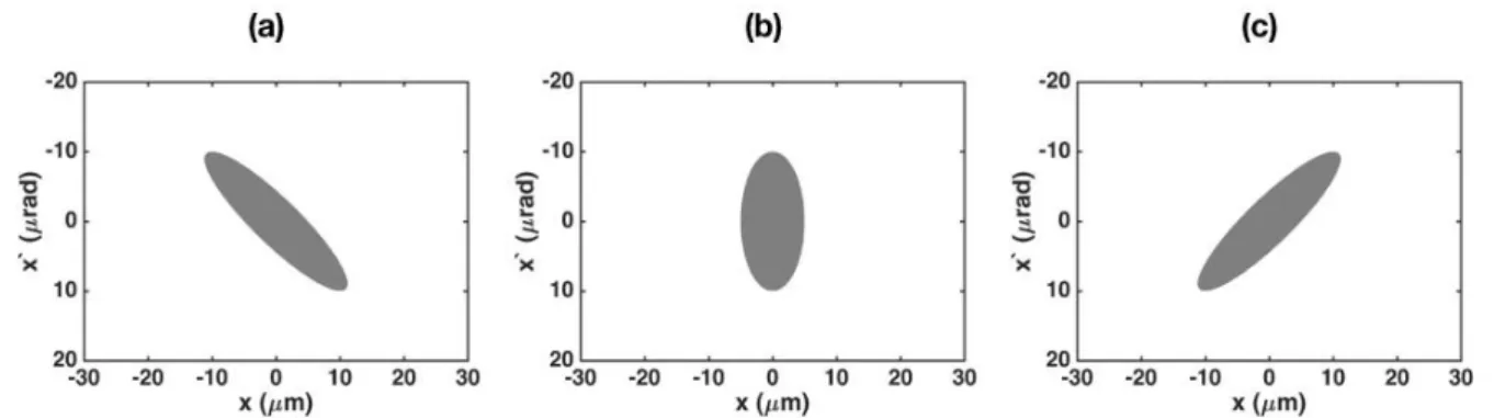
The evolution of parameters (1.13) – (1.15) for a beam propagating in free space is as follows: for a converging beam, initially we have 𝛼 > 0, at focus 𝛼 = 0 and after focus when the beam diverges 𝛼 < 0. The beam emittance (area of the ellipse in trace-space) is constant. Before focus, a particle that has 𝑥 > 0 must also have 𝑥′ < 0 (the beam converges, Fig. 1.8
(a)). After focus, it is the opposite (Fig. 1.8 (c)). At focus (𝛼 = 0, Fig. 1.8 (b)) the beam reaches its minimal possible size in 𝑥: the ellipse is “upright”.
Chapter 1. Particle accelerators, laser and beam physics
e. Periodic focusing systems
In conventional accelerators particle beams are transported along the beam lines over kilometers. A periodic set of lenses maintains the beam close to the axis by refocusing it regularly. In real space, each particle undergoes pseudo harmonic oscillations with a wavelength 𝜆 =2𝜋
√𝜅. In trace-space, the beam ellipse accomplishes complete rotations around
the origin [Humphries 02]. Scientists define the phase advance per cell 𝝈 as the fraction of the complete rotation of the beam ellipse in trace-space between two consecutive lenses. In
Fig. 1.9 is plotted a particle trajectory in a periodic focusing system, along with the envelope evolution. We can say that the beam is correctly matched if the envelope oscillations are stable, such as in Fig. 1.9. A stability threshold can be found from the derivation of the parameters (1.13) – (1.15) [Humphries 02]. This matching condition is the requirement to be able to maintain the beam close to the axis of the beam line, while keeping a constant emittance over the full length of the accelerator.
f. Sources of emittance growth
Preserving the normalized emittance during acceleration and transport along the beam line is a major and well-known issue. Focusing components provide linear forces that do preserve
Figure 1.8: Evolution of the trace-space ellipse of a particle beam moving in real space without focusing force, when the beam crosses a focal spot. (a) Before focus. (b) At focus. (c) After focus. The area of the ellipse stays constant, so does the extremum of 𝑥’.
Figure 1.9: Periodic focusing system. The abscise is the position along the line, normalized to the distance between two consecutive lenses, the vertical axis represents the transverse dimension of the beam. From [Humpries 02].
the emittance. SLAC National Accelerator Laboratory provides for instance a beam with typical 𝑥 and 𝑦 normalized emittances of 100 𝑚𝑚. 𝑚𝑟𝑎𝑑 × 10 𝑚𝑚. 𝑚𝑟𝑎𝑑 at the experimental area, for a minimal beam size of 30 𝜇𝑚.
Several phenomena are sources of emittance growth, some of them, occurring in Plasma Wakefield Acceleration experiments are listed below with further details.
Nonlinear focusing forces:
Beams facing nonlinear focusing forces such as in the wakefield seen by large transverse size bunches in a plasma wakefield accelerator do not conserve their emittance. Such focusing fields distort the ellipsoidal shape of the beam in trace-space. For perfectly harmonic forces, the trace-space beam ellipse rotates without any distortion.
In plasma or laser wakefield accelerator schemes, Betatron oscillations can occur to all accelerated particles [Rousse 04]. In the case of a highly nonlinear blowout regime, the focusing force due to the ion cavity is perfectly linear in 𝑟 (the distance of the electron undergoing Betatron motion to the axis). However, far from the axis the focusing force can become higher than the linear force close to the axis. Therefore, outer particles phase in trace-space can evolve faster. This is directly responsible for distortion of the ellipse in trace-space. Particle will spread in phase-space and form a uniform circular shape with a higher area than the initial ellipse.
This phenomenon occurs also in conventional accelerators beam lines, in which periodic focusing quadrupole doublets are used to transport the beam (when matching conditions are met, nonlinearity has the smallest effect, while it can be very strong when mismatched). The ellipse in trace-space therefore rotates as the beam propagates in the line. If the focusing forces are nonlinear, outer particle phase advance will evolve faster as well. In that case, the trace-space beam ellipse will be distorted.
Linear forces dependent on the beam longitudinal coordinate
If the force depends on the longitudinal coordinate, emittance growth will occur. This phenomenon can happen for instance in the linear regime of PWFA or LWFA. If the plasma wave is sampled by a beam whose longitudinal size is of the same order as the variation length of the wakefield in the longitudinal direction, then the particles will rotate with different speeds in trace-space [Mehrling 12].
Chromaticity spread
Beam energy spread implies a variation of the emittance. If one considers Betatron oscillations of particles in the blow-out regime of Plasma Wakefield Acceleration, particles in trace-space 𝑥 − 𝑥′ rotate around the origin at the frequency 𝜔𝑏=
𝜔𝑝/√2𝛾 [Lu 06b, Corde 13]. 𝜔𝑏 depends on gamma, therefore particles with
different energies will rotate at different velocities. As many Betatron oscillations occur during the acceleration process, this will contribute to distort the beam ellipse in trace-space [Michel 06].
Chapter 1. Particle accelerators, laser and beam physics
The first chapter was an introduction to particle accelerators and to the technologies underlying particle energy gain in these facilities. Examples of applications were given and the necessary increase in acceleration gradient to push fundamental research further was illustrated. A solution to this issue could be plasma based acceleration. Two sections of the first chapter were dedicated to some of the physics concepts useful in the manuscript: laser and particle beam physics. The next chapter is dedicated to the presentation of plasma physics results, results necessary to derive the theory behind plasma acceleration of particles.
Introduction to plasma physics
Plasma-based acceleration techniques rely on several important concepts of plasma physics that will be presented here. After the introduction of the basic concepts and parameters, a simple model of electromagnetic waves propagation in plasmas is derived and the fluid description of a plasma and its formalism are introduced.
Contents
1. Plasmas ... 23
a. Electronic plasma frequency ... 23 b. Debye length ... 24
2. Ionization ... 25
a. Low-Field Ionization ... 25 b. Multi-Photon Ionization ... 27 c. Tunnel Ionization and Barrier Suppression Ionization ... 26
3. Fluid description of a plasma ... 28
4. Electromagnetic waves in plasmas ... 29