HAL Id: pastel-00996571
https://pastel.archives-ouvertes.fr/pastel-00996571
Submitted on 26 May 2014HAL is a multi-disciplinary open access
archive for the deposit and dissemination of sci-entific research documents, whether they are pub-lished or not. The documents may come from
L’archive ouverte pluridisciplinaire HAL, est destinée au dépôt et à la diffusion de documents scientifiques de niveau recherche, publiés ou non, émanant des établissements d’enseignement et de
water and microstructure : An approach by
microindentation
Qing Zhang
To cite this version:
Qing Zhang. Creep properties of cementitious materials : effect of water and microstructure : An approach by microindentation. Other. Université Paris-Est, 2014. English. �NNT : 2014PEST1054�. �pastel-00996571�
´
Ecole Doctorale: SIE
Discipline: Mat´eriaux et Structures
Pr´esent´ee par Qing ZHANG
Propri´et´es m´ecaniques des mat´eriaux cimentaires: effet de
l’eau et de la microstructure, une approche par
microindentation
Soutenue publiquement `a l’´Ecole des Ponts ParisTech le 13 F´evier, 2014 James J. BEAUDOIN Bernhard PICHLER Jean-No¨el ROUX Matthieu VANDAMME Ellis GARTNER Bruno ZUBER
Professeur, University of Ottawa Professeur, TU Vienna
ICPEF, IFSTTAR
IPEF, ´Ecole des Ponts ParisTech Docteur, Lafarge Docteur, Lafarge Rapporteur Rapporteur Directeur de th`ese Examinateur Examinateur Examinateur Laboratoire Navier ´
Ecole des Ponts ParisTech 77455 Champs-sur-Marne
I thank my supervisors Dr. Matthieu Vandamme, Dr. Ellis Gartner, Dr. Bruno Zuber and Dr. Jean-N¨oel Roux for their guidances in the PhD research project.
I thank my family and my friends for their continuous supports, es-pecially during my three years’ doctoral studies.
Many thanks to various supports (including funding) from Lafarge Re-search Center. Thank Gilles Chanvillard, Pipat Termkhajornkit, Jef-frey Chen, R´emi Barbarulo, QuocHuy Vu, Arnaud Delaplce, Gabriel Pham and Bruno Huet for their fruitful advices and for those inter-esting discussions on the thesis. I thank my lovely colleagues: Herv´e Noyalet, Fabienne Begaud, Sandrine Brun, Sylvette Chiale, Cather-ine Bouillon, KarCather-ine Jacquemet, Marc Fouilhe, Sara Scapol, Fran¸coise Tardy and Agn`es Monier for their helps, supports and for the good moments that we passed together.
effect of water and microstructure.
An approach by microindentation
Abstract
Cementitious materials such as concrete, cement and gypsum are widely used in construction, as the raw materials of which they are made are abundant on Earth. Such trend is unlikely to change in the coming decades. But these materials suffer from creep. The creep of cementitious materials is a complex issue. On one hand, in cementi-tious materials creep is often coupled with other phenomena such as drying, hydration and cracking, and can be influenced by various pa-rameters such as temperature, level of stress, water content and mix design. On the other hand, measuring creep by traditional macro-scopic creep testing is time-consuming (creep test on concrete is rec-ommended to be carried out over several months in order to provide a reliable characterization of long-term creep) and tedious, since exper-imental parameters need to be well controlled over extensive periods of time.
This thesis studied microindentation at the scale of cement paste or gypsum plaster for the assessment of long-term basic creep proper-ties of cementitious materials, by comparing creep functions obtained by minutes-long microindentation testing with those obtained with macroscopic creep experiments which lasted up to years. For cement paste, the comparison was made at the scale of concrete with the aid of upscaling tools. The study validated that minutes-long microin-dentation testing can provide a measurement of the long-term creep properties of cementitious materials.
pastes and C2S pastes as well as on compacts of synthetic C-S-H,
port-landite (CH) and their mixtures prepared by compaction of powders. For all samples considered, we identified the right micromechanical model that allows predicting the results. The choice of micromechan-ical model was consistent with microstructural observations.
The effect of relative humidity was studied by conditioning and test-ing some of those materials (i.e., C3S paste, compact of C-S-H, and
compact of CH) in various relative humidities ranging from 11% to 94%. Relative humidity had a significant effect on creep: for all ma-terials tested, a greater humidity led to a greater creep. The compact of portlandite was the most sensitive to relative humidity, probably because creep occurs at interfaces between portlandite crystals. For C3S paste, a linear relation was identified between long-term creep
properties and water content at relative humidities ranging from 11% to 75%.
Finally, we proposed micromechanical models that allow predicting long-term basic creep properties of cementitious materials with a wide range of volume fraction of crystalline phase and over a wide range of relative humidities.
Keywords: creep, cementitious materials, microindentation, microstruc-ture, relative humidity
cimentaires: effet de l’eau et de la
microstructure, une approche par
microindentation
R´
esum´
e
Les mat´eriaux cimentaires tels que le b´eton, le ciment et le plˆatre sont largement utilis´es dans la construction, les mati`eres premi`eres dont ils sont faits ´etant abondantes sur Terre. Cette tendance ne de-vrait pas changer dans les prochaines d´ecennies. Mais ces mat´eriaux subissent l’impact du fluage. Le fluage des mat´eriaux cimentaires est une probl´ematique complexe. D’une part, dans les mat´eriaux cimen-taires, le fluage est souvent coupl´e avec d’autres ph´enom`enes tels que le s´echage, l’hydratation et la fissuration, et peut ˆetre influenc´e par diff´erents param`etres comme la temp´erature, le niveau de contrainte, la teneur en eau et la formulation. D’autre part, la mesure du fluage par un test macroscopique traditionnelle du fluage requiert du temps (il est recommand´e de r´ealiser l’essai de fluage du b´eton sur plusieurs mois afin de donner une caract´erisation fiable du fluage `a long terme) et s’av`ere fastidieuse, puisque les param`etres exp´erimentaux doivent ˆetre bien contrˆol´es sur de longues p´eriodes de temps.
Cette th`ese ´etudie la microindentation `a l’´echelle de la pˆate de ci-ment ou du plˆatre pour ´evaluer les propri´et´es de fluage propre `a long terme des mat´eriaux cimentaires, en comparant les fonctions de fluage obtenues par des tests de microindentation de quelques min-utes avec celles obtenues par des exp´eriences macroscopiques de flu-age r´ealis´ees pendant de longues ann´ees. Pour la pˆate de ciment, la comparaison a ´et´e faite `a l’´echelle du b´eton `a l’aide d’une certaine homog´en´eisation. L’´etude a valid´e le fait que un test de
microinden-Une fois valid´ee la technique d’indentation, nous avons ´etudi´e l’effet de la microstructure (c’est-`a-dire la distribution des phases) et celui de l’eau sur le fluage propre `a long terme des mat´eriaux cimentaires. L’effet de la microstructure a ´et´e ´etudi´ee sur des mat´eriaux tels que des pˆates de C3S et de C2S ainsi que sur des compacts de C-S-H
synth´etique, de portlandite (CH) et leurs m´elanges pr´epar´es par com-pression de poudres. Une attention particuli`ere a ´et´e consacr´ee `a cr´eer des compacts avec de grandes fractions volumiques de phase cristalline. Pour tous les ´echantillons examin´es, nous avons identifi´e le bon mod`ele microm´ecanique qui permette de pr´edire les r´esultats. Le choix du mod`ele microm´ecanique concorde avec les observations microstructurales.
L’effet de l’humidit´e relative a ´et´e ´etudi´e par le conditionnement et l’indentation de certains de ces mat´eriaux (par exemple la pˆate de C3S, de compact de C-S-H et de compact de CH) dans diff´erents
humidit´e relative allant de 11% `a 94%. L’humidit´e relative a eu un effet significatif sur le fluage : pour tous les mat´eriaux test´es, une plus grande humidit´e a conduit `a un fluage plus important. Le compact de portlandite fut le plus sensible `a l’humidit´e relative, sans doute parce que le fluage se produit au niveau des interfaces entre les cristaux de portlandite. Pour la pˆate de C3S, une relation simple a ´et´e identifi´ee
entre les propri´et´es de fluage `a long terme et la teneur en eau.
Enfin, nous avons propos´e des mod`eles microm´ecaniques qui permet-tent la pr´ediction des propri´et´es de fluage `a long terme de mat´eriaux cimentaires avec une large gamme de fraction volumique de phase cristalline et sur une gamme d’humidit´es relatives ´etendue.
Mots cl´es: fluage, mat´eriaux cimentaires, microindentation, microstruc-ture, humidit´e relative
cimentaires: effet de l’eau et de la
microstructure, une approche par
microindentation
R´
esum´
e long
Les mat´eriaux cimentaires sont largement utilis´es dans la construc-tion, les mati`eres premi`eres dont ils sont faits ´etant abondantes sur Terre. Cette tendance ne devrait pas changer dans les prochaines d´ecennies. Mais ces mat´eriaux subissent l’impact du fluage. Le fluage des mat´eriaux cimentaires est une probl´ematique complexe. D’une part, dans les mat´eriaux cimentaires, le fluage est souvent coupl´e avec d’autres ph´enom`enes tels que le s´echage, l’hydratation et la fis-suration, et peut ˆetre influenc´e par diff´erents param`etres comme la temp´erature, le niveau de contrainte, la teneur en eau et la formula-tion. D’autre part, la mesure du fluage par un test macroscopique traditionnelle du fluage requiert du temps (il est recommand´e de r´ealiser l’essai de fluage du b´eton sur plusieurs mois afin de donner une caract´erisation fiable du fluage `a long terme) et s’av`ere fastidieuse, puisque les param`etres exp´erimentaux doivent ˆetre bien contrˆol´es sur de longues p´eriodes de temps.
Initi´e par Lafarge Centre de Recherche et Laboratoire Navier `a ´Ecole des Ponts ParisTech , le projet de recherche vise les objectifs suivants . Tout d’abord, le projet vise `a trouver une r´eponse claire sur la validit´e des tests de fluage indentation pour la mesure des propri´et´es de flu-age sur des mat´eriaux cimentaires. Le deuxi`eme objectif est de mieux comprendre le fluage des mat´eriaux cimentaires. Deux sous-objectifs sont identifi´es. Dans ciment Portland, de deux types distincts de com-posants existent : composant amorphe tel que le silicate de calcium
tion de ces composants et de leur organisation spatiale. Le premier objectif est d’´etudier par l’effet de la microstructure, `a savoir la dis-tribution de proportion et de l’organisation spatiale des min´eraux, sur le fluage de base `a long terme des mat´eriaux cimentaires. Bien que certaines ´etudes ont montr´e que la teneur en eau a un effet sur les propri´et´es de fluage des mat´eriaux cimentaires, avec les donn´ees disponibles dans la litt´erature, l’influence de la quantit´e d’eau sur base de longue dur´ee propri´et´es de fluage des mat´eriaux cimentaires n’est pas claire. Ainsi, le second objectif est d’´etudier l’effet de l’eau sur le fluage propre `a long terme.
La th`ese se compose de quatre parties. La premi`ere partie est une in-troduction qui pr´esente le contexte de la recherche (chapitre 1) et une revue de la litt´erature sur les tests de fluage (chapitre 2). A partir de l’analyse d’indentation (chapitre 3), la partie II traite de la validation de l’indentation pour la mesure de fluage sur divers mat´eriaux `a base de ciment, `a savoir, la pˆate de ciment (chapitre 4) et plˆatre (chapitre 5). Une fois la technique des tests de p´en´etration est valid´ee, la partie III se concentre sur la caract´erisation de la fa¸con dont `a long terme des propri´et´es de fluage de base de mat´eriaux cimentaires sont influenc´es par la microstructure et de l’eau. L’effet de la microstructure est ex-amin´ee en consultant les mat´eriaux obtenus par hydratation , tels que C3S et C2 pˆates (chapitre 6) et par compactage de poudre,
c’est-`a-compacts (chapitre 7). L’effet de l’eau est ´etudi´ee sur les pˆates et les pactes qui ont atteint l’´equilibre hygral avec des humidit´es relatives diff´erentes (chapitre 8). La partie III se termine par le chapitre 9, dans lequel nous utilisons l’approche microm´ecanique pour construire des mod`eles qui permettent de pr´edire `a long terme des propri´et´es de flu-age de base de mat´eriaux cimentaires en fonction de la microstructure et de l’humidit´e relative. Les mod`eles sont valid´es par des r´esultats exp´erimentaux. Partie IV est un d´eterminant dont nous pr´esentons les principaux r´esultats, les contributions, les limites et perspectives (chapitre 10).
trait´e par le sujet de recherche, c’est-`a-dire le fluage des mat´eriaux cimentaires. L’introduction est suivie ensuite par les objectifs de recherche ainsi que les b´en´efices scientifiques et industriels. Le chapitre se termine par un aper¸cu de la th`ese.
Le chapitre 2 pr´esente une revue de la litt´erature sur les mat´eriaux ci-mentaires et leur fluage. Les mat´eriaux cici-mentaires sont des mat´eriaux multi-´echelles et poreux. D`es lors, le fluage de ces mat´eriaux inter-vient `a diff´erentes ´echelles et peut ˆetre largement influenc´e par la pr´esence d’eau en porosit´e. Les effets li´es au changement d’humidit´e, `a la teneur en eau, `a la temp´erature, au niveau de contrainte et `a la formulation sur le fluage des mat´eriaux cimentaires ont ´et´e examin´es sur la base d’´etudes r´ecentes. L’origine du fluage des mat´eriaux ci-mentaires est probablement due `a une combinaison de m´ecanismes. Le comportement du fluage des mat´eriaux cimentaires `a court et long terme est contrˆol´e par diff´erentes cin´etiques et peut ˆetre caus´e par diff´erents m´ecanismes. Pour la pr´ediction du fluage, un regard a ´et´e port´e sur les mod`eles les plus r´epandus.
Le chapitre 3 est d´edi´e `a la pr´esentation de la technique d’indentation. Nous commen¸cons par pr´esenter un test d’indentation typique et l’ap-pareil d’indentation utilis´e dans l’´etude. Puis nous pr´esentons l’analyse pour ´evaluer le module d’indentation M et la duret´e d’indentation H issus d’un test d’indentation. Enfin, nous ´elargissons l’analyse aux calculs des propri´et´es de fluage `a partir d’un test d’indentation. Le chapitre 4 est consacr´e `a comparer des tests de fluage par microin-dentation de quelques minutes sur de la pˆate de ciment avec des tests de fluage macroscopique de plusieurs ann´ees sur le b´eton d’une part et de plusieurs mois sur la pˆate de ciment d’autre part (toutes les tests de fluage macroscopique par compression uniaxiale ont ´et´e r´ealis´es par Le Roy [1996]. Pour l’ensemble de ces tests, apr`es une p´eriode transitoire, la fonction de fluage a ´et´e d´ecrite de fa¸con satisfaisante par une fonction logarithmique du temps. Les p´eriodes transitoires
Les modules de fluage (qui d´efinissent donc le taux de fluage loga-rithmique `a long terme) des ´echantillons de b´eton ont ´et´e estim´es `a partir de la microindentation r´ealis´ee `a l’´echelle des pˆates de ciment en combinaison avec des mod`eles microm´ecaniques. Ces estimations se sont r´ev´el´ees ˆetre proportionnelles au module de fluage mesur´e sur les ´echantillons de b´eton par des tests de macroscopie uni axiale usuelle, montrant ainsi que la microindentation de quelques minutes peut per-mettre de mesurer les propri´et´es de fluage `a long terme des mat´eriaux cimentaires.
Le chapitre 5 s’int´eresse `a comparer des tests de fluage par microinden-tation de quelques minutes avec des tests de fluage par macroscopie de plusieurs jours, c’est-`a-dire des test de fluage par flexion sur du plˆatre – un mat´eriau cimentaire cristallin. Une partie de ces tests de fluage par flexion a ´et´e conduite par Pachon-Rodriguez[2011]. Les fonctions de fluage propre sp´ecifique ont ´et´e mesur´ees `a la fois par microinden-tation et par flexion. Qualitativement, des tendances comparables ont ´et´e obtenues avec ces deux types des tets. Quantitativement, pour toutes les tests par indentation, apr`es une p´eriode transitoire, la fonction de fluage propre sp´ecifique ´etait bien d´ecrite par une fonc-tion logarithmique du temps. Comme ce qui a ´et´e fait au chapitre 4, nous retenons le module de fluage Ci et le temps caract´eristique
par indentation τi pour caract´eriser la fonction de fluage. Les
fonc-tions de fluage propre sp´ecifique obtenues pas flexion n’ont jamais ´et´e des fonctions logarithmiques du temps. En revanche, ces fonctions de fluage ont ´et´e bien d´ecrites par la somme d’une fonction logarith-mique du temps et d’une fonction lin´eaire. La fonction logarithlogarith-mique a ´et´e caract´eris´ee par un module de fluage en flexion et un temps car-act´eristique en flexion. Pour la plupart des ´echantillons, les modules de fluage du plˆatre mesur´es par indentation ont ´et´e pratiquement (soit 4 ´echantillons sur 6) en parfaite concordance avec les modules de flu-age en flexion mesur´es par flexion, ce qui prouve que l’indentation est une technique valid´ee pour caract´eriser les propri´et´es de fluage des
cin´etique de fluage logarithmique s’est av´er´e bien inf´erieur par inden-tation que par flexion, ce qui montre que l’indeninden-tation de quelques minutes permet d’obtenir rapidement la cin´etique logarithmique des mat´eriaux cimentaires. La partie non logarithmique du fluage propre sp´ecifique du plˆatre observ´e par test de flexion est probablement due au fait que, durant le text de flexion, une partie de l’´echantillon est en tension.
Apr`es avoir valid´e la technique d’indentation pour la mesure de flu-age sur des mat´eriaux cimentaire, dans le chapitre 6, nous appliquons cette technique pour ´etudier les propri´et´es de fluage des mat´eriaux cimentaires. Les propri´et´es m´ecaniques telles que le module de Young E, la duret´e d’indentation H ainsi que les propri´et´es de fluage, `a savoir le module de fluage Ci et le temps caract´eristique τi sur des pˆates C3S
et C2S, ont ´et´e obtenues par microindentation. La microstructure des
pˆates test´ees a ´et´e caract´eris´ee par la fraction volumique de chaque phase d´eduite `a partir du degr´e d’hydratation estim´e `a partir de la mesure du retrait chimique. Nous avons ´etabli une relation lin´eaire entre le module de fluage Ci et la duret´e d’indentation H ainsi qu’une
fonction de puissance entre le module de fluage Ci et le module de
Young E. La relation entre les propri´et´es m´ecaniques et la fraction volumique de chaque phase est explor´ee en tra¸cant simplement les propri´et´es m´ecaniques en fonction de la fraction volumique de chaque phase. Nous abordons ´egalement l’effet de la porosit´e sur ces pro-pri´et´es m´ecaniques. Les r´esultats confirment que E, H et Ci
aug-mentent lorsque le degr´e d’hydratation augmente. La proportion de chaque phase et les propri´et´es m´ecaniques des pˆates C3S et C2S seront
utilis´ees ult´erieurement dans le chapitre 9 pour valider le mod`ele mi-crom´ecanique.
Le chapitre 7 est consacr´e `a la pr´esentation d’une ´etude sur les pro-pri´et´es m´ecaniques d’´echantillons pr´esentant une porosit´e similaire mais des fractions volumiques de C-S-H et de CH diff´erentes. Ces
des ´echantillons et la densit´e des poudres. Tous les ´echantillons ont ´et´e conditionn´es sous 11% d’humidit´e relative ou bien sous condi-tions satur´ees en eau. Les propri´et´es m´ecaniques de ces compacts ont ´et´e caract´eris´ees par microindentation. Nous avons trouv´e une am´elioration claire du module de Young E, de la duret´e d’indentation H et du module de fluage Ci des compacts quand la fraction
volu-mique de CH sous 11% d’humidit´e relative augmentait au cur du solide, tandis que dans des conditions satur´ees en eau aucune aug-mentation sensible n’´etait observ´ee. Nous avons aussi constat´e que les propri´et´es m´ecaniques des compacts telles que d´efinies ci-dessus sous 11% d’humidit´e relative ´etaient nettement sup´erieures `a celles observ´ees dans des conditions satur´ees en eau, ce qui a permis de d´emontrer l’impact important de l’eau sur les propri´et´es m´ecaniques des compacts. Pour les ´echantillons avec une quantit´e ´elev´ee de CH, le temps caract´eristique d’indentation τi soit le temps requis pour
attein-dre la cin´etique de fluage logarithmique, s’est r´ev´el´e plus important dans des conditions satur´ees en eau que sous une humidit´e relative de 11%.
Dans le chapitre 8, la pˆate C3S, le compact de C-S-H et le
com-pact de CH en ´equilibre hydrique selon des niveaux d’humidit´e rel-ative diff´erents ont ´et´e test´es par microindentation. Pour l’ensemble des mat´eriaux ´etudi´es, il a ´et´e observ´e que la duret´e d’indentation H diminuait quand l’humidit´e relative augmentait. Le module de Young E de la pˆate C3S s’est quant `a lui r´ev´el´e constant `a des niveaux
d’humidit´e relative diff´erents, tandis que pour le compact de CH et de C-S-H, une baisse du module de Young E ´etait observ´ee `a des hu-midit´e relatives ´elev´ees. Le module de fluage Ci a baiss´e de mani`ere
g´en´erale avec une hausse d’humidit´e relative. Pour le compact de CH, la baisse du module Ci s’est v´erifi´ee sur l’ensemble d’humidit´es
rela-tives consid´er´es, alors que pour la pˆate C3S et le compact de C-S-H,
nous avons identifi´e une humidit´e relative critique en dessous lequel le module Ci variait. En combinant nos observations avec la
con-aucun effet sur le module de fluage mais que le fait de d´esaturer les pores dans C-S-H ´etait par contre responsable des variations observ´ees sur le module de fluage `a des niveaux d’humidit´e relative variables. Autrement dit, l’eau dans le C-S-H est responsable du fluage propre `a long terme de la pˆate C3S et du compact de C-S-H. Pour tous les
´echantillons analys´es, il a ´et´e constat´e une ´evolution fragment´ee du temps caract´eristique d’indentation en fonction de l’humidit´e relative: il semble qu’il existe une humidit´e relative critique au-del`a duquel τi
est une fonction d´ecroissante de l’humidit´e relative et en-de¸c`a duquel τi est une fonction croissante de l’humidit´e relative. Sur la pˆate C3S,
en consid´erant les donn´ees sur le module de fluage et l’isotherme de d´esorption, une relation lin´eaire reliant le module de fluage et le teneur en eau a ´et´e trouv´ee pour une humidit´e relative compris entre 11% et 75%.
Avec tous les r´esultats exp´erimentaux collect´es dans les chapitres avant, une approche microm´ecanique est utilis´ee pour interpr´eter les r´esultats exp´erimentaux et pour mod´eliser l’effet de la microstructure et de l’eau sur le fluage dans le chapitre 9. En consid´erant les pro-pri´et´es m´ecaniques et la distribution de chaque phase des mat´eriaux obtenue par des exp´eriences, nous proposons un mod`ele de mise `a l’´echelle pour les pˆates C3S et C2S et un autre mod`ele pour les
com-pacts. Les mod`eles propos´es sont aussi utilisables pour le module de Young E. Pour la pˆate C2S et les compacts, le choix du mod`ele
est guid´e par les informations sur la microstructure obtenues par MEB. L’effet de l’humidit´e relative est en outre int´egr´e aux diff´erents mod`eles propos´es.
La th`ese finie par le chapitre 10, dans lequel nous pr´esentons un r´esum´e des principales conclusions du projet de recherche. Sur la base de ces conclusions et des contributions, plusieurs limites et per-spectives sont d´etaill´ees.
Contents xiv
Nomenclature xxiv
List of Figures xxv
List of Tables xxxiii
I
Introduction
1
1 General presentation 2
1.1 Context . . . 3
1.1.1 Concrete for construction . . . 3
1.1.2 Creep of concrete . . . 3
1.1.3 The complexity of creep of concrete . . . 4
1.1.4 Potential for measuring creep by indentation testing . . . . 4
1.2 Research motivation and objectives . . . 5
1.3 Industrial and scientific benefits . . . 6
1.4 Outline of thesis . . . 6
2 Bibliographic study 8 2.1 Cementitious materials . . . 9
2.2 Terminologies of deformations . . . 11
2.3 Creep testing on cementitious materials . . . 14 2.4 Review of experimental results on creep of cementitious materials 18
2.4.2 Effect of temperature on creep properties of cementitious
materials . . . 21
2.4.3 Effect of stress level on creep . . . 23
2.4.4 Effect of mix design on creep . . . 25
2.5 Creep theories of cementitious materials . . . 26
2.6 Creep prediction . . . 29
2.6.1 Assumptions and limitations . . . 29
2.6.2 Models and comparison . . . 30
2.7 Chapter conclusions . . . 31
II
Microindentation creep test on cementitious
materi-als - validation for measuring creep of cementitious
ma-terials by microindentation
33
3 Indentation technique 34 3.1 Indentation test . . . 353.2 Indentation apparatus in Lafarge Research Center . . . 36
3.3 Assessment of indentation modulus and indentation hardness . . . 37
3.3.1 Indentation modulus . . . 37
3.3.2 Determination of projected contact area . . . 40
3.3.3 Indentation hardness . . . 42
3.4 Assessment of creep properties from an indentation . . . 43
3.4.1 Indentation into a linear viscoelastic material . . . 43
3.4.2 Indentation into a plastic linear viscoelastic material . . . 46
3.5 Chapter summary . . . 49
4 Comparative study on cement paste and concrete 50 4.1 Chapter introduction . . . 52
4.2 Materials and methods . . . 52
4.2.1 Materials . . . 52
4.2.2 Uniaxial compressive creep experiments on concrete and cement . . . 56
4.3.1 Creep functions of compressive tests and indentation tests 61 4.3.2 Direct comparison of microindentation on cement paste
with uniaxial compression on cement paste . . . 61
4.3.3 Comparison of long-term logarithmic kinetics of creep . . . 65
4.4 Discussion . . . 73
4.4.1 On the coefficient between contact and uniaxial creep mod-ulus . . . 73
4.4.2 On the choice of homogenization scheme . . . 74
4.4.3 On the ability of indentation to characterize long-term creep 75 4.4.4 On the quality of the creep experiments . . . 76
4.5 Chapter conclusions . . . 78
5 Comparative study on gypsum 80 5.1 Chapter introduction . . . 82
5.2 Materials and methods . . . 84
5.2.1 Sample preparation . . . 84
5.2.2 Bending experiments . . . 86
5.2.3 Indentation experiments . . . 89
5.3 Results and discussion . . . 91
5.3.1 Flexural strength, indentation hardness and Young’s mod-ulus of gypsum samples . . . 91
5.3.2 Qualitative comparison of creep function . . . 91
5.3.3 Quantitative comparison of creep parameters . . . 93
5.3.4 Discussion . . . 100
5.4 Chapter conclusions . . . 103
III
Effect of microstructure and relative humidity on
long-term basic creep of cementitious materials
105
6 Creep properties of C3S and C2S pastes 106 6.1 Chapter introduction . . . 1086.2.3 Assessment of phase distribution in hydrating C3S and C2S
pastes . . . 112
6.2.4 Microindentation creep testing on hydrating C3S and C2S pastes . . . 117
6.3 Results and discussion . . . 118
6.3.1 Distribution of phases of hydrating C3S and C2S pastes . . 118
6.3.2 Mechanical properties of C3S and C2S pastes . . . 119
6.3.3 Link between porosity and mechanical properties of C3S and C2S pastes . . . 123
6.3.4 Link between volume fraction of solid phases and mechan-ical properties of C3S and C2S pastes . . . 124
6.4 Chapter conclusions . . . 124
7 Creep properties of compacts of CH, synthetic C-S-H and their mixtures 128 7.1 Chapter introduction . . . 130
7.2 Materials and methods . . . 132
7.2.1 Preparation and characterization of synthetic C-S-H . . . . 133
7.2.2 Preparation of compacts . . . 134
7.2.3 Phase distribution in compacts . . . 138
7.2.4 Indentation experiments on compacts . . . 140
7.3 Results and discussions . . . 142
7.3.1 Mechanical properties of compacts . . . 142
7.3.2 Link between microstructure and mechanical properties . . 147
7.3.3 A glance at the effect of water on the mechanical properties of compacts . . . 147
7.4 Chapter conclusions . . . 150
8 Effect of relative humidity on creep properties of cementitious materials 153 8.1 Chapter introduction . . . 155
8.3 Results and discussions . . . 159
8.3.1 Raw results from indentation testing . . . 159
8.3.2 Mechanical properties of C3S paste and compacts at various relative humidities . . . 162
8.3.3 Influence of water content on the creep properties of C3S paste . . . 165
8.3.4 Effect of relative humidity on creep properties of C3S paste and compacts . . . 167
8.4 Chapter conclusions . . . 170
9 Modeling by micromechanical approach 171 9.1 Short reminder of basic elements of linear homogenization theory 172 9.2 Upscaling of contact creep modulus . . . 178
9.3 A two-step homogenization model for C3S paste or C2S paste . . . 184
9.3.1 Description of model . . . 184
9.3.2 Determination of input parameters . . . 188
9.3.3 Results of calibration . . . 189
9.3.4 Integrating effect of relative humidity on creep in the model 191 9.3.5 Example . . . 192
9.4 A two-step homogenization model for compacts of mixtures . . . . 193
9.4.1 Description of model . . . 193
9.4.2 Hypotheses on creep properties . . . 197
9.4.3 Determination of input parameters of the model . . . 198
9.4.4 Results of calibration . . . 199
9.5 Discussion . . . 204
9.6 Chapter conclusions . . . 207
IV
Conclusions and perspectives
209
10 Conclusions 210 10.1 Research contributions . . . 211Greek alphabet
β correcting parameter for Galin-Sneddon solution ǫ(x) strain tensor in representative volume element Σ(X) stress tensor at homogenized scale
σ(x) stress tensor in representative volume element ξ displacement vector
E(X) strain tensor at homogenized scale I second unit tensor
ǫf flexural strain, 1
ǫir irreversible strain due to creep, 1
ǫr reversible creep strain due to creep, 1
Γ(t) gamma function I four-order unit tensor
Ω volume occupied by representative volume element
Φ diameter, mm
φ porosity, 1
σf flexural stress, Pa
τf bending characteristic time, s
τH duration of the holding phase of indentation test, s
τi indentation characteristic time, s
τL duration of the loading phase of indentation test, s
τU duration of the unloading phase of indentation test, s
τu uniaxial compression characteristic time, s
θ half-cone angle, ◦
English alphabet
A localization tensorAr mean localization tensor of phase r C stiffness tensor
Chom homogenized stiffness tensor Cr stiffness tensor of phase r P Hill’s tensor
S Eshelby’s tensor RH relative humidity, %
X space variable at homogenized scale
x space variable within representative volume element
Cf flexural creep modulus, Pa
Ci contact creep modulus, Pa
Cu uniaxial creep modulus, Pa
Cv volumetric creep modulus, Pa
D deflection, m
d depth, m
D0 instantaneous deflection, m
E Young’s modulus, Pa
E0 Young’s modulus at moment of loading, Pa
Eef f effective modulus, Pa
fr volume fraction of phase r, Pa
G shear modulus, Pa
g geometry coefficient of monomial indentation probe, 1 g0 geometry coefficient of monomial indentation probe, 1
Ghom homogenized shear modulus, Pa
Gr shear modulus of phase r, Pa
J(t) creep compliance, Pa
Jf(t) flexural creep compliance, Pa
Ju(t) uniaxial creep compliance, Pa
K bulk modulus, Pa
l span of two supports in a bending test, m L(t) contact creep compliance, Pa
lheter characteristic length of heterogeneity, m
lRV E characteristic length of representative volume element, m
lsample characteristic length of sample, m
M indentation modulus, Pa
m mass, g
ma mass of absorbed water, g
Mm molar mass, g/mol
P load, N
Pmax maximum load, N
r radius, m
S contact stiffness, N/m
s complex number in Laplace domain Sch chemical shrinkage, mL/g
T temperature, ◦C
t time, s
t′
time starting from loading, s
V volume, m3
hi average operator
L Laplace transform operator div divergence operator
2.1 Multi-scale view of concrete [Vandamme, 2008]. . . 9 2.2 Dimensional range of solids and pores in a hydrated cement paste
[Mehta and Monteiro, 2006]. . . 10 2.3 Photo of uniaxial compressive creep testing machine [Lee et al.,
2006]. . . 15 2.4 Schema of tensile creep machine with dead weight [Rossi et al.,
2013b]. . . 16 2.5 Schema of bending creep testing machine with dead weight. . . . 17 2.6 Indentation test on duralumin with a tungsten carbide conical
in-denter [Testwell and Tabor, 1961]. . . 17 2.7 a) Total deformation and b) shrinkage deformation of thin cement
paste tested in different hygral conditions: sample a at 99% relative humidiy, sample b at relative humidities varying from 99% to 75% within a day; and for sample c: at 75% humidity. [Baˇzant et al.,
1973]. . . 20 2.8 Basic creep strain of concrete samples with complete drying before
and without drying before creep testing, compared with drying creep strain on similar sample, figure from [Acker and Ulm, 2001]. 20 2.9 Compliance function of hydrated cement paste (w/c=0.5) after
re-saturation from different drying pre-treatments [Tamtsia and Beaudoin, 2000]. . . 22 2.10 Specific basic creep of concrete tested at the age of 1 day under
four stress levels from 10% compressive strength (0.1fc) to 40% of
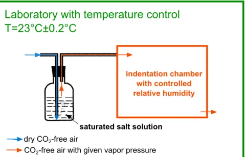
3.3 Schematic presentation of a simple system to control relative hu-midity during indentation testing. . . 37 3.4 Schematic representation of a section through an indentation
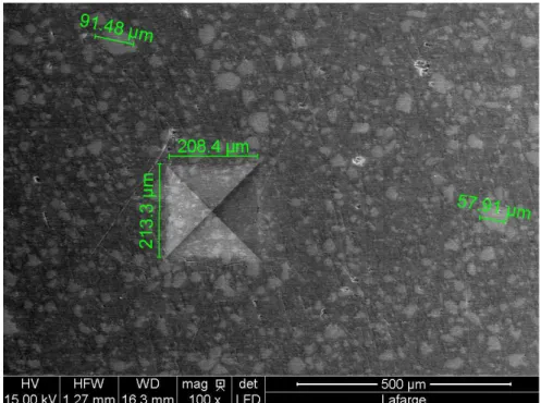
show-ing various parameters used in Oliver and Pharr method, schematic adapted from [Oliver and Pharr,1992]. . . 40 4.1 Scanning electron microscopy picture of the surface of an indented
cement sample. . . 59 4.2 Uniaxial basic creep functions of cement paste samples obtained
by uniaxial compressive creep testing [Le Roy,1996]. . . 62 4.3 Uniaxial basic creep functions of concrete obtained from uniaxial
compressive creep testing [Le Roy, 1996]. . . 62 4.4 Contact creep functions L(t) − 1/M0 of cement paste samples
ob-tained by microindentation. For each sample, out of the 5 experi-ments performed, only the median curve is displayed. . . 63 4.5 Young’s modulus E0 of the cement paste samples, determined by
indentation test when assuming a Poisson’s ratio ν = 0.20 and determined by macroscopic uniaxial compression test. s/c stands for the mass ratio of silica fume to clinker. Experimental data for compression is from Marchand [1992]. . . 64 4.6 Derivatives with respect to time of the contact creep compliance
obtained by microindentation test and of the uniaxial creep com-pliance obtained by macroscopic compression test on cement paste sample P38-0SV. . . 65 4.7 Examples of basic creep functions and of the best fits obtained
with Eq. 4.3 or Eq. 4.4: a) uniaxial creep function obtained by uniaxial compression of cement paste P38-0LC, b) uniaxial creep function obtained by uniaxial compression of concrete B28-1, and c) contact creep function obtained by microindentation of cement paste P38-0SV. . . 68 4.8 Uniaxial creep modulus Cu,cemversus contact creep modulus Ci for
of concrete estimated from microindentation creep experiments performed on cement paste, by considering, for the upscaling from cement paste to concrete, a) a Mori-Tanaka scheme and b) the upscaling model of Vu et al. [2010]. . . 72 4.10 Basic creep function of concrete sample B33-1D, together with Eq.
4.4 fitted on all data points and with Eq. 4.4 fitted on data points until 1800 days only. . . 73 5.1 Degrees of hydration obtained by NMR and isothermal calorimetry,
at 25◦C, and isothermal heat flow over time [Jaffel et al., 2006]. . 83
5.2 Schematic figure of the apparatus used for three-point bending creep testing. . . 87 5.3 Creep functions of gypsum samples conditioned in 50% relative
humidity measured by a) indentation creep testing and b) three-point bending testing at 50% relative humidity, at 23◦C. . . . 92
5.4 Summary of a) flexural creep functions from three-point bend-ing creep testbend-ing in immersed conditions (results from [ Pachon-Rodriguez,2011]) and b) contact creep functions from indentation creep testing in 100% relative humidity on gypsum samples im-mersed in various solutions: G08-T imim-mersed in Trilon-P solution, G08-P immersed in phosphate solution and G08-G immersed in gypsum solution. . . 94 5.5 Effect of water content on creep properties of gypsum observed by
a) bending testing b) indentation testing. Sample G08-G was im-mersed in solution saturated with gypsum, sample G08 was condi-tioned in 50% relative humidity. Data of bending testing on sample G08-G in immersed conditions is from [Pachon-Rodriguez, 2011]. . 95 5.6 Summary of contact creep functions from indentation creep
test-ing and their correspondtest-ing fits with Eq. 4.3, on gypsum samples immersed in various solutions: G08-T immersed in Trilon-P solu-tion, G08-P immersed in phosphate solution and G08-G immersed in gypsum solution. . . 96
ples immersed in various solutions: G08-T immersed in Trilon-P solution, G08-P immersed in phosphate solution and G08-G im-mersed in gypsum solution. . . 97 5.8 Time-dependent uniaxial strain obtained by uniaxial compressive
creep testing in water-saturated condition on gypsum aggregates samples a) tested at different compressive stress levels b) with dif-ferent average size of gypsum grains [De Meer and Spiers, 1997]. . 102 6.1 Fracture surface of hydrated C3S paste at age of 90 days observed
by scanning electron microscopy. . . 109 6.2 Volumetric phase distribution in a cement paste as a function of
the degree of hydration α, at water-to-cement ratio of w/c=0.6. The diagram applies to a sealed hydration without exchange of water with the surroundings. Due to the high w/c, full hydration with degree of hydration α = 1 of the cement can theoretically be obtained [Jensen and Hansen, 2001]. . . 113 6.3 Contact creep function L(t) − 1/M0 of C3S paste sample A42 with
water-to-cement ratio w/c=0.42 tested at age of 10 days with a 10000-seconds-long holding phase. . . 120 6.4 a) Indentation hardness H versus Young’s modulus E, contact
creep modulus Ci b) versus the Young’s modulus E and c) versus
the indentation hardness H from indentation tests performed on pastes of C3S and C2S. . . 122
6.5 Porosity versus a) contact creep modulus Ci b) Young’s modulus
E and c) indentation hardness H of C3S pastes and C2S pastes. . 125
6.6 a) Contact creep modulus Ci, b) Young’s modulus E, c)
indenta-tion hardness H versus volume fracindenta-tion of C-S-H, that of CH and unhydrated clinker, i.e., C3S for C3S paste and C2S for C2S paste. 126
hydrated cement paste; II: sliced and then compressed hydrated cement paste; III: compacts of hydrated cement powder. The porosity of samples was calculated from the weight, volume and degree of hydration, choosing 3.15g/cm3 for the density of
unhy-drated cement clinker, and 2.6g/cm3 for the density of hydration
products. . . 131 7.2 X-ray diffraction pattern of prepared C-S-H. . . 135 7.3 Schematic presentation of the compaction cell and of the
com-paction process. Between two cycles, the hollow cylinder mold is turned over for the load to be applied in two directions. . . 136 7.4 Compact of synthetic C-S-H. . . 137 7.5 Porosity of compacts measured by different experimental techniques.139 7.6 Schematic presentation of the surfaces of a disk-like compact. . . . 140 7.7 Contact creep function L(t) − 1/M0 of compact of C-S-H
(Cpt-CSH), compact of CH (Cpt-CH), and compact of mixture Cpt-M4 conditioned a) under water-saturated conditions and b) under 11% relative humidity, at 23◦C. . . . 143
7.8 Contact creep modulus Ci versus a) Young’s modulus E and b)
indentation hardness H, from indentation tests performed on com-pacts in water-saturated conditions and at 23◦C. . . . 145
7.9 Contact creep modulus Ci versus a) Young’s modulus E and b)
indentation hardness H, from indentation tests performed on com-pacts at 11% relative humidity and at 23◦C. . . . 146
7.10 a) Young’s modulus E, b) indentation hardness H and c) contact creep modulus Ci of compacts from indentation tests on
water-saturated compacts. fCSHis the volume fraction of C-S-H and fCH
is the volume fraction of CH. . . 148 7.11 a) Young’s modulus E, b) indentation hardness H and c) contact
creep modulus Ci of compacts from indentation tests performed at
11% relative humidity. fCSH is the volume fraction of C-S-H and
perature of 23◦C. . . . 151
8.1 Mass evolution of initially water-saturated samples conditioned at 11% relative humidity: the shape of C3S paste sample and the
compact of C-S-H sample is a split part of a 3.5mm-thick disk and the shape of compact of CH is a disk. . . 158 8.2 Median contact creep function of a) C3S paste, b) compact of
C-S-H and c) compact of CH, at various relative humidities. For C3S paste in water-saturated conditions, we take C3S paste tested
at age of 56 days in water-saturated conditions from section 6.3. For compacts, the results in water-saturated conditions are from section 7.3. . . 160 8.3 Indentation hardness H versus a) Young’s modulus E, b) contact
creep modulus Ci, and Young’s modulus E versus c) contact creep
modulus Ci of C3S paste with w/c=0.42 (A42), compact of
C-S-H (Cpt-CSC-S-H) and compact of CC-S-H (Cpt-CC-S-H) at various relative humidities. . . 163 8.4 Indentation hardness H, contact creep modulus Ci and Young’s
modulus E of C3S paste, compact of C-S-H and compact of CH at
various relative humidities. . . 164 8.5 Indentation characteristic time τi of C3S paste, compact of C-S-H
and compact of CH in equilibrium with various relative humidities. 165 8.6 Desorption isotherm of a 180-days-old C3S paste cured in water,
with water-to-cement ratio w/c=0.42. . . 166 8.7 The contact creep modulus Ci in function of water content w for
C3S paste. . . 166
8.8 Largest radius rpe of pores remaining saturated at various relative
humidities. . . 168 9.1 Schematic presentation of two-step homogenization model for C3S
aged at the age of 1 year. CH and C-S-H were identified by X-ray spectrometry. The features were taken and analyzed by C.Bouillon from Lafarge Research Center. . . 187 9.3 Contact creep modulus Ci of C3S and C2S pastes obtained from
experimental measurement and from the two-step homogenization model. . . 190 9.4 Young’s modulus E of C3S and C2S pastes obtained from
microin-dentation experiment and predicted with the two-step homogeniza-tion model. . . 190 9.5 Contact creep modulus Ci,CSHof C-S-H calibrated by applying the
two-step homogenization model presented in section9.3 and linear fit of the calibrated Ci,CSH at relative humidities between 11% and
75%. . . 191 9.6 Contact creep moduli of C3S paste (w/c=0.42) at relative
humidi-ties of 25%, 50% and 75% predicted by the model in function of a) degree of hydration α and b) porosity (without pores in the C-S-H phase). . . 194 9.7 SEM observation of a) compact of C-S-H b) compact of CH. The
features were taken and analyzed by C. Bouillon from Lafarge Re-search Center. . . 195 9.8 SEM observation of compact of mixture Cpt-M3, with (in volume)
52% of C-S-H, 26% of CH and 22% of porosity. The features were taken and analyzed by C. Bouillon from Lafarge Research Center. 196 9.9 Schematic presentation of two-step homogenization model for
com-pacts. . . 196 9.10 Contact creep moduli of C-S-H and CH in various relative
humidi-ties, calibrated with a self-consistent scheme on experimental result of compacts of pure C-S-H and pure CH. . . 200 9.11 Contact creep modulus Ci of compacts from experiments and
pre-dicted by the model presented in section9.4 a) in water-saturated conditions, b) in 11% relative humidity. . . 201
ative humidity. . . 202 9.13 Contact creep modulus Ci of C3S paste, obtained from indentation
and predicted by the proposed two-step model for pastes with the input parameter of C-S-H phase calibrated on C-S-H compact. . . 205 10.1 Schematic summary of experimental data obtained in the research
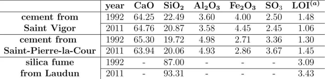
2.1 Input parameter of different creep prediction models . . . 31 3.1 Theoretical contact area function of different indentation probes . 41 4.1 Mass percentage of chemical components in the clinkers and silica
fume used in this study. Data is provided by manufacturer. For clinker and silica fume, respectively, only mass percentages greater than 1% and than 3% are given.
(a) LOI: loss on ignition. . . 53
4.2 Physical properties of clinker and silica fume used in this study. Data is provided by manufacturer. . . 53 4.3 Proportion of the main phases in the clinkers used in 2011 to
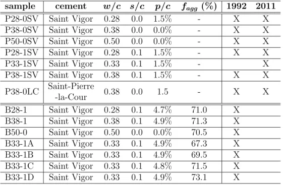
prepare cement paste samples for microindentation testing, deter-mined by Rietveld X-ray diffraction quantification. Data is from the manufacturer (Lafarge). . . 53 4.4 Mix formulations of cement paste samples (the denomination of
which starts with the letter P) and concrete samples (the denomi-nation of which starts with the letter B) prepared in this study. w/c denotes the water-to-cement mass ratio; s/c stands for the mass ratio of silica fume to clinker; p/c denotes the superplasticizer to cement ratio; fagg denotes the volume fraction of aggregates (i.e.,
gravel and sand) in concrete. Samples prepared in 1992 were used for uniaxial creep experiments; samples prepared in 2011 were used for microindentation creep experiments. . . 55 4.5 Experimental parameter settings of indentation experiments on
4.7 Contact creep modulus Ci obtained by microindentation creep
ex-periment on cement paste and uniaxial creep modulus Cu,cem
ob-tained by uniaxial compression creep experiment on cement paste. 69 4.8 Uniaxial creep modulus Cu,con measured by uniaxial compression
creep experiments on concrete and contact creep modulus Ci,con of
concrete estimated from microindentation creep experiments per-formed on cement paste. . . 71 5.1 Chemical component of the hemihydrate calcium sulphate used for
the preparation of gypsum sample. . . 85 5.2 Labeling, water-to-hemihydrate ratio w/h, porosity φ of gypsum
samples and environment in which they were conditioned. . . 86 5.3 Experimental parameter setting during bending creep testing. . . 87 5.4 Summary of the experimental parameters of indentation
experi-ments in room condition and wet condition. . . 90 5.5 Mechanical properties measured by three-point bending testing or
indentation testing. . . 90 5.6 Summary of creep functions parameters from bending creep
test-ing and indentation creep testtest-ing. Sample G07, G08 and G09 were conditioned and tested in 50% relative humidity; Sample G08-G,G08-T and G08-P were immersed in solutions, tested in immersed conditions by bending and at 100% relative humidity by indentation. . . 99 6.1 Physical properties of C3S and C2S. . . 111
6.2 Labeling and main control parameter of C3S and C2S paste samples.112
6.3 Density and molar mass of different phases in cement paste, used for the determination of volumetric phase distribution. . . 117 6.4 Ages at testing of hydrating C3S and C2S pastes. . . 117
6.5 Experimental parameter settings of indentation experiments on C3S and C2S pastes. . . 118
and A42 with water-to-cement ratio w/c=0.42, and C2S paste, i.e.,
B42 with water-to-cement ratio w/c=0.42. . . 119 6.7 Mechanical properties of hydrating C3S and C2S pastes. . . 121
7.1 Phase distribution for compacts of C-S-H, CH and of their mixtures.139 7.2 Experimental parameter settings of indentation experiments on
compacts. . . 141 7.3 Mechanical properties of compact Cpt-M6 on flat surface and on
cross-section obtained by indentation testing. . . 142 7.4 Young’s modulus E, indentation hardness H, contact creep
modu-lus Ci and the characteristic time τi obtained by microindentation
of compacts of C-S-H, CH and their mixtures. . . 144 8.1 Relative humidity created by various saturated salt solutions at
various temperatures. Data is obtained by applying the best-fit function in Tab.1 of [Greenspan,1977] . . . 157 8.2 Experimental parameter settings of indentation experiments on
compacts and on C3S paste at various relative humidities. . . 159
8.3 Young’s modulus E, indentation hardness H, contact creep mod-ulus Ci and indentation characteristic time τi of C3S paste, with
w/c=0.42 (labeled as A42), compact of C-S-H (labeled as Cpt-CSH) and compact of CH (labeled as Cpt-CH) tested in various relative humidities. For C3S paste in water-saturated conditions,
we take the value of C3S paste tested at age of 56 days in
water-saturated conditions (see in Tab. 6.7). For compacts, the results in water-saturated conditions are from Tab. 7.4. . . 161 9.1 Parameters in microscale and macroscale and their relations. . . . 173 9.2 Young’s modulus E, contact creep modulus Ci, Poisson’s ratio ν
and aspect ratio of all phases used in the model. The parameters in blue are calibrated parameters. . . 189
water-saturated conditions used in the model. The parameters in blue are calibrated parameters. . . 203
General presentation
R´
esum´
e
Ce chapitre est un r´esum´e g´en´eral du projet de recherche. Le chapitred´emarre par une introduction au probl`eme trait´e par le sujet de recherche, c’est-`a-dire le fluage des mat´eriaux cimentaires. L’introduction est suivie ensuite par les objectifs de recherche ainsi que les b´en´efices scientifiques et industriels. Le chapitre se termine par un aper¸cu de la th`ese.
Abstract
This chapter is a general summary of the research project. Thechapter starts with an introduction to the problem addressed by the research, i.e., the creep of cementitious materials. The introduction is followed by the research objectives and the scientific and industrial benefits. The chapter ends with an outline of the thesis.
1.1
Context
1.1.1
Concrete for construction
Concrete is a composite material composed of coarse granular material (aggre-gates or fillers) embedded in a hard matrix of material (cement or binder) that fills the space between the aggregates and glues them together [Li,2011].
Concrete is widely used all over the world: in mass, twice as much as steel, wood, plastics, and aluminum combined. Concrete is the most used man-made material in the world, with nearly three tons used annually per person [World Business Council for Sustainable Development, 2013]. In terms of effectiveness, price and performance, concrete can hardly be replaced by other existing building materials. Currently over 20 billion tons of concrete are produced per year and by 2050, the use of concrete is predicted to reach four times the 1990 level.
1.1.2
Creep of concrete
Creep is a time-dependent deformation occurring under and induced by, a con-stant sustained stress [Neville, 1971]. Since the first publication on the creep of reinforced concrete in 1907 [Hatt, 1907], the creep of concrete has been studied for more than 100 years but its fundamental mechanism is still rather poorly understood. For instance, in the past 10 years, the term “creep” appeared in 14% of original research papers published in the journal ‘Cement and Concrete Research’.
Creep can be either beneficial or detrimental for a concrete structure. On one hand, creep can bring a beneficial effect by relieving undesirable stresses due to strains imposed by shrinkage or extreme initial temperature. Thus in cer-tain occasions, thanks to creep, the risk of cracking can be reduced [F´ed´eration Internationale du B´eton, 2013]. On the other hand, creep can reduce the bene-ficial effects of stresses artibene-ficially imposed for improving the serviceability of a structure. In the case of pre-stressed concrete, creep causes a loss of pre-stress over time in structure which reduces the serviceability of the structure [Magura et al., 1963]. Last but not least, the long-term reliability of structures may be largely affected by creep as creep increases by an important factor the initial de-formations of a concrete structure [Baˇzant and Panula, 1980]. Either beneficial
or detrimental, creep plays an important role in concrete structure in terms of stability, serviceability and durability, both at short term and long term. The calculation of time-dependent deformations is recommended by most widely used codes for design of concrete structures, such as the ACI code, the fib model code, the GL2000 code, etc.
1.1.3
The complexity of creep of concrete
Creep of concrete is a complex issue for several reasons. Firstly, due to the fact that cement and concrete are multi-scale heterogeneous materials: creep can be observed at different scales ranging from that of concrete to cement paste, down to individual hydration products. Secondly, creep is sensitive to a variety of parameters: moisture, temperature, stress level, curing condition and mix design (i.e., water-to-cement ratio, admixture, aggregates) can influence creep [Neville,
1971]. Thirdly, cementitious materials are obtained by hydration of binders, and the hydration can last months to years. As a consequence, cementitious materials evolve with time and the creep properties depend on the age at which a given material is tested. Because of those various reasons, in the past century, despite major successes, the phenomenon of creep (and shrinkage) is still far from being fully understood [Baˇzant, 2001].
The difficulties in measuring creep at macroscopic scale by classical mechan-ical testing (compressive, tensile, bending) somehow make the issue even more complicated. Indeed, in order to provide a reliable prediction of long-term creep, creep testing on concrete is recommended to be carried out over hundreds of days [Jir´asek and Dobrusk`y, 2012; Le Roy, 1996]. With such a long duration of test, experimental parameters as temperature, applied load and moisture content and distribution within the sample are difficult to control.
1.1.4
Potential for measuring creep by indentation testing
Indentation or hardness testing has long been used for characterization and qual-ity control of materials [VanLandingham, 2003]. The indentation technique is used more and more widely for characterizing the mechanical properties of mate-rials at very small scales: microindentation for testing on the scale of micrometer and nanoindentation on the scale of nanometer. Recently, different studies show
the possibility of measuring viscous properties by indentation, on cementitious materials [Davydov et al.,2011;Pichler and Lackner,2009;Vandamme and Ulm,
2009, 2013]. Compared with conventional macroscopic creep testing, indenta-tion creep testing is carried out at a much smaller microscopic scale but under a much higher stress. How to compare the result with traditional macroscopic creep testings on cementitious materials is still unclear.
1.2
Research motivation and objectives
Initiated by Lafarge Research Center and Laboratoire Navier at ´Ecole des Ponts ParisTech, the research project has the following objectives.
Firstly, the project aims at finding a clear answer on the validity of indentation creep testing for the measurement of creep properties on cementitious materials1.
The word “validate” here in our context refers to testing new methods developed by Vandamme [2008] on indentation creep with respect to classical macroscopic creep experiments.
The second objective is to better understand creep of cementitious materials. Two sub-objectives are identified:
• In Portland cement, two distinct types of components exist: amorphous component such as calcium silicate hydrate, i.e., C-S-H and crystalline components such as portlandite and unhydrated clinker particles. The mi-crostructure of cementitious materials can be characterized by the propor-tion of those components and their spatial organizapropor-tion. The first objective is to study the effect of microstructure, i.e., the proportion distribution and the spatial organization of minerals, on long-term basic creep of cementi-tious materials.
• Though some studies showed that water content has an effect on the creep properties of cementitious materials [Acker and Ulm, 2001; Baˇzant et al.,
1
Hydraulic binder is a material (with or without an aggregate) that provides plasticity, cohesive, and adhesive properties when it is mixed with water. Those properties are necessary for its placement and formation into a rigid mass. The term cementitious material refers to the material created by mixing hydraulic binder with water, i.e., via hydration reaction. In the thesis, the term “cementitious material” can refer to cement paste, concrete, C3S and C2S
1973;Cilosani,1964;Wittmann,1970], with the available data in literature, the influence of amount of water on long-term basic creep properties of cementitious materials is unclear. So the second objective is to study the effect of water on long-term basic creep.
1.3
Industrial and scientific benefits
In parallel of fulfilling those objectives mentioned above, there are some additional useful results that can be brought by our research, both on the basis of industrial application and that of research.
• A fast, (i.e., minutes-long) and well-controlled experimental technique to measure the long-term basic creep behavior of cementitious materials • Fundamental understandings on the long-term basic creep properties of
ce-mentitious materials influenced by their microstructures and by the amount of water
• A model to predict the long-term basic creep behavior of cementitious ma-terials as a function of relative humidity and of their microstructure
1.4
Outline of thesis
The thesis consists of four parts. Part I is an introductory part which provides the context of research (chapter 1) and a literature review on creep testing (chap-ter 2). Starting with indentation analysis (chap(chap-ter 3), the part II deals with the validation of indentation for the measurement of creep on various cementitious materials, i.e., cement paste (chapter 4) and gypsum plaster (chapter 5). Once the technique of indentation testing is validated, part III focuses on characterizing how the long-term basic creep properties of cementitious materials are influenced by microstructure and water. The effect of microstructure is scrutinized by look-ing at both materials obtained by hydration, such as C3S and C2S pastes (chapter
6) and by compaction of powder, i.e., compacts (chapter 7). The effect of water is studied on pastes and compacts that achieved hygral equilibrium with various
relative humidities (chapter 8). The part III ends with chapter 9 in which we use micromechanical approach to build models that predict the long-term basic creep properties of cementitious materials as a function of microstructure and of relative humidity. The models are validated with experimental results. Part IV is a conclusive one in which we present the main findings, contributions, limitations and perspectives (chapter 10).
Bibliographic study
R´
esum´
e
Ce chapitre pr´esente une revue de la litt´erature sur les mat´eriauxcimentaires et leur fluage. Les mat´eriaux cimentaires sont des mat´eriaux multi-´echelles et poreux. D`es lors, le fluage de ces mat´eriaux intervient `a diff´erentes ´echelles et peut ˆetre largement influenc´e par la pr´esence d’eau en porosit´e. Les effets li´es au changement d’humidit´e, `a la teneur en eau, `a la temp´erature, au niveau de contrainte et `a la formulation sur le fluage des mat´eriaux cimentaires ont ´et´e examin´es sur la base d’´etudes r´ecentes. L’origine du fluage des mat´eriaux cimentaires est probablement due `a une combinaison de m´ecanismes. Le com-portement du fluage des mat´eriaux cimentaires `a court et long terme est contrˆol´e par diff´erentes cin´etiques et peut ˆetre caus´e par diff´erents m´ecanismes. Pour la pr´ediction du fluage, un regard a ´et´e port´e sur les mod`eles les plus r´epandus.
Abstract
This chapter gives a literature review on cementitious materials andthe creep of those materials. Cementitious materials are multi-scale and porous materials. Therefore, creep of those materials happens at different scales and can be largely influenced by the presence of water in porosity. The effects of moisture change, water content, temperature, stress level and mix design on creep of ce-mentitious materials were reviewed based on recent studies. The origin of creep of cementitious materials is probably due to a combination of mechanisms. The short-term and long-term creep behaviors of cementitious materials are controlled by different kinetics and may be due to different mechanisms. For creep predic-tion, a glance was given at the most widespread models.
Figure 2.1: Multi-scale view of concrete [Vandamme, 2008].
2.1
Cementitious materials
Cementitious materials are multi-scale materials. For example, concrete by na-ture is highly heterogeneous over a large range of length scales. In engineering application, concrete is a composite made of aggregates (e.g., sand, gravel, fiber) and binder (e.g., cement) which bonds the aggregates together. At a smaller scale than concrete, cement paste can be regarded as a composite of unhydrated clinker, hydrated products and voids. The unhydrated clinker consists of vari-ous calcium silicates, including tricalcium silicate (Ca3SiO5 or C3S), dicalcium
silicate (Ca2SiO4 or C2S) and tricalcium aluminate (3CaO·Al2O3, C3A), calcium
aluminoferrite as other common components. The hydrated products in cement paste may include calcium silicate hydrates (C-S-H), calcium hydroxide (CH), calcium sulfoaluminates, ettringite and monosulfate with various sizes and ge-ometries. Each hydrate has its own microstructure. Hydrates with complicated microstructures such as C-S-H are widely studied as a heterogeneous material with substructures at smaller scales. A multi-scale plotting of concrete is pre-sented in Fig. 2.1.
Cementitious materials are porous materials, due to the voids present at different scales in those materials. According to Mehta and Monteiro [2006], classified by the sizes, the following voids in a cement paste can be found: the
of those voids in cement paste is presented in Fig. 2.2.
The pore size distribution in C-S-H is till studied intensively today, but vari-ous terminologies can be already found in literature to classify the pores in C-S-H, such as: “interlayer pores”(1nm) and “gel pores”(3nm) given by Feldman and Sereda [1970]; “intraglobular pores”(1nm) and two types of “globule pores”(1-10nm) from the model ofTennis and Jennings[2000]. The lengths in parentheses were the characteristic sizes of the corresponding pores given by Muller et al.
[2012]. In following chapters, we apply the terms from Feldman and Sereda
[1970] for the pores in C-S-H.
The porosity at different scales may have various influences on the proper-ties of cementitious materials. The porosity in C-S-H may contribute to drying shrinkage and creep; the capillary porosity may contribute to the strength and permeability while the small capillary porosity may contribute to drying shrink-age and creep [Mehta and Monteiro, 2006]. As a consequence, the quantity, the size distribution and the connectivity of porosity influence the physical and me-chanical properties of cementitious materials. The meme-chanical behavior of porous materials is significantly influenced by the pore fluid. As the fluid in porosity is naturally water or, more precisely, saturated aqueous solution of minerals, the mechanical behaviors of cementitious materials could be sensitive also to mois-ture change which replaces water with moist air for instance.
Figure 2.2: Dimensional range of solids and pores in a hydrated cement paste [Mehta and Monteiro, 2006].
2.2
Terminologies of deformations
Since this thesis is focused mainly on time-dependent deformations, this section is dedicated to define the time-dependent deformations to which cementitious materials are submitted.
Neville et al.[1983] precisely defined creep as ‘a deformation occurring under, and induced by, a constant sustained stress’. Cementitious materials can shrink even with absence of applied loads and these deformations are called shrinkage, when temperature is constant [Baˇzant and Wittmann, 1982].
Depending on whether there is moisture exchange with external environment or not, shrinkage can be categorized as drying shrinkage and autogeneous shrink-age. Drying shrinkage refers to the contracting of a hardened concrete mixture due to the loss of water. [Tazawa, 1998] defines autogeneous shrinkage as the deformation occurring without moisture transfered to the exterior surrounding environment, and without external load: it is affiliated with the hydration of ce-ment particles. During the very first hours after mixing, autogeneous shrinkage is fully attributed to chemical shrinkage [Holt,2005], which is the volume change due to the difference between the volume occupied by the products of hydration and that of mixture of water and clinker. Once cement is hardened, autogeneous shrinkage can result from self-desiccation [Tazawa and Miyazawa,1995], which is the localized drying resulting from a decreasing relative humidity in the concrete’s internal pores [Holt, 2005].
As a consequence of the existence of shrinkage, the experimentally measured time-dependent deformation ǫtotal of a cementitious material by applying a
con-stant load contains not only the incon-stantaneous deformation as elastic deforma-tion (denoted as ǫelastic), and time-dependent deformation of total creep (noted
as ǫcreep) but also the shrinkage deformation (denoted as ǫsh). ThoughHua[1995]
andSicard et al.[1996] showed that creep and shrinkage of cementitious materials are not independent phenomena and one may interact with the other, the assump-tion of superposiassump-tion of deformaassump-tion of creep and shrinkage stays the principal method to interpret experimental results and also to model creep deformations:
classified by whether drying occurs or not:
• Basic creep strain, denoted as ǫb, is termed as the time-dependent
defor-mation without moisture change and at constant temperature [Baˇzant and Wittmann,1982].
• Drying creep strain, denoted as ǫd, is defined as the excess of creep at drying
over the sum of shrinkage and basic creep [Baˇzant and Yunping, 1994]. At variable temperature, an extra term called thermal transitional creep strain is introduced. The thermal transitional creep strain, denoted as ǫT, is the extra
deformation due to temperature change. With the above definitions, the total creep strain can be expressed by Eq. 2.2 as the sum of basic creep strain, drying creep strain and transitional creep strain if one supposes that different creep deformations are additive:
ǫcreep = ǫb + ǫd+ ǫT (2.2)
There exists also other ways to categorize the creep deformations of cementitious materials. Here, we will mention the two commonly applied classifications:
• irreversible creep and reversible creep • short-term creep and long-term creep
Depending on whether the creep deformation can be recovered or not by complete unloading, creep can be divided as reversible creep strain (the part that can be recovered from complete unloading, denoted as ǫr) and irreversible creep
strain (the part of creep that can not be recovered from complete unloading, denoted as ǫir):
ǫcreep = ǫir + ǫr (2.3)
The creep strains are often normalized by applied load. The term ‘specific creep’ as one may find in much literature is defined as the creep strain divided by applied stress. For the convenience of illustration below, we also define a term “specific basic creep” as the specific creep without strains due to drying or temperature change. The specific creep equals to the specific basic creep if there is no drying
or temperature change. For drying creep strain and thermal transitional strain one can define their corresponding specific strains.
The creep of cementitious materials can also be phenomenologically classified as short-term creep and long-term creep. The term of “short-term creep” and “long-term creep” appear very often in various studies, yet definition is not very clear. The “short-term creep” on an experimental basis refers to the creep behav-ior measured in relatively short duration, which can vary from 1 day to 1 month [Bernard et al.,2003; Guo et al., 2005;Jo et al., 2007;Khadraoui, 2012;Tamtsia and Beaudoin, 2000] by macroscopic creep testing. On the other hand, the term “long-term creep” refers to a test duration that may vary from 3 months to years [Chami et al., 2009; Han and Yang, 2003; Jo et al., 2007; Li et al., 2012; Manzi et al.,2013;Mi`as et al.,2013; Salau,2003]. On the basis of creep kinetics, short-term creep and long-short-term creep are used to present different kinetics of creep. The short-term creep kinetics last only a few days, while the long-term kinetics is characterized by a pronounced aging without an asymptote [Ulm et al., 1999]. One can notice that the long-term creep or short-term creep may refer to different time scales on the basis of testing or on the basis of creep kinetics.
To characterize the creep behavior of cementitious materials, apart from using time-dependent creep deformation, one can also use creep function and creep compliance. The creep function, also called specific creep strain, is the creep deformation normalized by applied stress. The creep function has the same unit as compliance (ability to comply with deformation forces). Talking about the compliance, there is another term called creep compliance J, which is also widely used to characterize the creep behavior of cementitious materials. The creep compliance can be written as the sum of the instantaneous compliance at the moment of applying a load and the creep function. For example, the uniaxial creep compliance Ju equals to the instantaneous elastic compliance, i.e., the reciprocal
of Young’s modulus 1/E0 at the moment of loading plus a creep function f (t):
![Figure 2.2: Dimensional range of solids and pores in a hydrated cement paste [ Mehta and Monteiro , 2006 ].](https://thumb-eu.123doks.com/thumbv2/123doknet/2829919.68339/48.892.163.763.751.968/figure-dimensional-range-solids-hydrated-cement-mehta-monteiro.webp)
![Figure 2.4: Schema of tensile creep machine with dead weight [ Rossi et al. , 2013b ]](https://thumb-eu.123doks.com/thumbv2/123doknet/2829919.68339/54.892.276.648.213.488/figure-schema-tensile-creep-machine-dead-weight-rossi.webp)
![Figure 2.6: Indentation test on duralumin with a tungsten carbide conical inden- inden-ter [ Testwell and Tabor , 1961 ].](https://thumb-eu.123doks.com/thumbv2/123doknet/2829919.68339/55.892.278.650.705.982/figure-indentation-duralumin-tungsten-carbide-conical-testwell-tabor.webp)
![Figure 3.4: Schematic representation of a section through an indentation showing various parameters used in Oliver and Pharr method, schematic adapted from [ Oliver and Pharr , 1992 ].](https://thumb-eu.123doks.com/thumbv2/123doknet/2829919.68339/78.892.216.696.230.531/figure-schematic-representation-section-indentation-showing-parameters-schematic.webp)
![Figure 4.3: Uniaxial basic creep functions of concrete obtained from uniaxial compressive creep testing [ Le Roy , 1996 ].](https://thumb-eu.123doks.com/thumbv2/123doknet/2829919.68339/100.892.231.698.667.1027/figure-uniaxial-functions-concrete-obtained-uniaxial-compressive-testing.webp)
