HAL Id: pastel-00002804
https://pastel.archives-ouvertes.fr/pastel-00002804
Submitted on 30 Jul 2007HAL is a multi-disciplinary open access
archive for the deposit and dissemination of sci-entific research documents, whether they are pub-lished or not. The documents may come from teaching and research institutions in France or abroad, or from public or private research centers.
L’archive ouverte pluridisciplinaire HAL, est destinée au dépôt et à la diffusion de documents scientifiques de niveau recherche, publiés ou non, émanant des établissements d’enseignement et de recherche français ou étrangers, des laboratoires publics ou privés.
Estimation et contrôle d’un moteur diesel HCCI.
Estimation des systèmes périodiques.
Jonathan Chauvin
To cite this version:
Jonathan Chauvin. Estimation et contrôle d’un moteur diesel HCCI. Estimation des systèmes péri-odiques.. Mathematics [math]. École Nationale Supérieure des Mines de Paris, 2006. English. �pastel-00002804�
THÈSE
présentée à
L’École Nationale Supérieure des Mines de Paris par
J
ONATHAN
C
HAUVIN
en vue de l’obtention du titre de
DOCTEUR DE L’ÉCOLE DES MINES DE PARIS
Spécialité: Mathématiques et Automatique
Sujet de la thèse:
ESTIMATION ET CONTRÔLE D’UN MOTEUR
DIESEL HCCI. ESTIMATION DES SYSTÈMES
PÉRIODIQUES.
soutenue le 29 Septembre 2006 devant le jury composé de
MM. Carlos Canudas-de-Wit Rapporteur
Lino Guzzella
Rapporteur
Gilles Corde
Examinateur
Nicolas Petit
Examinateur
Pierre Rouchon
Examinateur
Jonathan CHAUVIN
ESTIMATION AND CONTROL OF
A DIESEL HCCI ENGINE.
ESTIMATION FOR TIME PERIODIC
SYSTEMS
Jonathan CHAUVIN
École Nationale Supérieure des Mines de Paris, Centre Automatique et Systèmes, 60, Bd. Saint-Michel, 75272 Paris Cedex 06, France.
Institut Français du Pétrole, 1 et 4 avenue du Bois Préau, 92852 Rueil-Malmaison, France.
E-mail : [email protected], [email protected] Url : www.cas.ensmp.fr/∼chauvin
Key words and phrases. — Engine control, HCCI, air path control, cylinder balanc-ing, motion plannbalanc-ing, dynamic inversion, periodic systems, periodic observers, Kalman filter.
Mots Clés. — Contrôle moteur, HCCI contrôle de la boucle d’air, équilibrage cylindre à cylindre, génération de trajectoire, inversion de dynamique, systèmes périodiques, obser-vateurs périodiques, filtre de Kalman.
ESTIMATION AND CONTROL OF A DIESEL
HCCI ENGINE. ESTIMATION FOR TIME
PERIODIC SYSTEMS
Jonathan CHAUVIN
vii
Résumé. — La combustion homogène Diesel (HCCI: Homogeneous Combustion Com-pression Ignition ) est caractérisée par un très haut taux de recirculation de gaz brûlés (EGR: Exhaust Gas Recirculation). Cette technique de combustion permet d’augmenter la qualité de mélange et la dilution dans le cylindre, tout en réduisant la formation des pol-luants. Malheureusement, ce procédé nuit à la stabilité de la combustion. Un compromis est nécessaire entre la stabilité de combustion et les performances du moteur, quantifiées en terme de couple produit et d’émissions polluantes. C’est là le rôle du contrôle moteur. À fins d’implementation de stratégie de contrôle, il est nécessaire d’estimer en temps réel l’évolution des paramètres de combustion qui ne sont pas directement mesurés par des capteurs.
Cette thèse, réalisée en collaboration avec l’IFP (Institut Français du Pétrole), propose des algorithmes de contrôle qui ont été validés expérimentalement sur un moteur HCCI quatre cylindres développé par l’IFP.
Nous décomposons le problème en trois parties et proposons des solutions, validées sur banc moteur, pour les deux premières.
La première étape consiste à réaliser le contrôle de la boucle d’air. Le but est d’estimer et de contrôler les masses aspirées par les cylindres (air frais et gaz brûlés). Ces masses s’expriment directement en fonction de la pression, la composition et les débits du col-lecteur d’admission. Des observateurs non linéaires permettent d’estimer ces variables, en n’utilisant que les capteurs présents sur les véhicules de série. La construction de ces observateurs ainsi que leurs preuves de convergence utilisent la méthode dite "d’injection de sortie" ainsi que la théorie de stabilité de Lyapunov. Une technique de génération de trajectoires est utilisée pour définir des consignes de débits (air frais et EGR). Cette loi de commande boucle ouverte prend explicitement en compte les contraintes physiques. Enfin, des contrôleurs de type proportionnel intégral (PI) sont utilisés pour garantir le suivi des consignes prescrites. Nous décrivons les résultats expérimentaux obtenus dans différents cas de figures, tels que des transitoires de charge et le cycle de référence européen.
La deuxième étape est l’équilibrage cylindre à cylindre. Le but est d’estimer les paramètres de combustion de chacun des cylindres afin de garantir que les cylindres ont la même combustion en dépit de la variabilité des éléments techniques les constituant. Pour cela, nous créons un observateur de couple instantané et un observateur de richesse cylindre à cylindre à partir de capteurs présents sur les véhicules de série. Nous exploitons l’information haute fréquence contenue dans les signaux mesurés (échantillonnage aux 6 degré vilebrequin). Ces observateur sont validés expérimentalement. Leur conception est nouvelle. Il s’agit d’un nouveau type d’observateurs asymptotiques reconstituant un nombre arbitraire de fréquences d’un signal périodique inconnu entrant dans un système linéaire périodique. Ces observateurs surpassent (à performances comparables) les filtres de Kalman en terme de temps de calculs. Ils sont inspirés des techniques de moyennisa-tion. Une méthodologie de réglage automatique est proposée et justifiée par l’extension à un nombre infini de fréquences.
La troisième étape est le contrôle de la boucle de fuel. Durant des transitoires de couple, la boucle de carburant doit suivre la dynamique plus lente de la boucle d’air (qui est typiquement 10 fois plus lente). Nous décrivons cette problématique et expliquons les principales difficultés.
viii
Abstract. — Homogeneous Combustion Compression Ignition (HCCI) combustion is characterized by a very high rate of Exhaust Gas Recirculation (EGR). This improves mix-ing and dilution in the cylinders, reduces pollutant formation at the expense of combustion stability. Thus HCCI engines requires real-time control to ensure a good trade–off between performance (in terms of torque production and low pollutant emissions) and combustion stability. Such closed-loop control are based on estimation of combustion parameters that are not directly measured.
This thesis, supported by IFP (Institut Français du Pétrole), proposes some control algorithms that have been tested experimentally on a 4–cylinders HCCI engine developed by IFP.
We decompose the control synthesis in three steps. We propose solutions with experi-mental validations for the first two steps.
The first step is air path control. The goal is to estimate and to control the masses entering in the cylinders (fresh air and burned gas). These masses are directly related to collector pressure, compositions and flow-rates. These variables are estimated via nonlinear observers using commercial cars sensors. Design and theoretical convergence proof follow linearization via output injection and Lyapunov argument. Feedforward control based on motion planning for differentially flat systems are used to derive the flow-rate set points (fresh air and EGR). This feedforward control takes explicitly physical input constraints into account. Finally, fast Proportional Integral (PI) controller are designed to track these step points using as measured values the above estimations. We describe experimental results for large torque transient and also for driving phases of the eurocycle.
The second step is cylinder balancing. The goal is to estimate and control the combustion parameters in order to guarantee that all the cylinders have the same combustion in any steady-state regime. For that, we design instantaneous torque and cylinder individual air/fuel ratio (AFR) observers using commercial car sensors. We exploit here the high-frequency information contained in the measured signals (sampling of 6 degree crank angle). Experimental results are reported. These results are based on a new class on asymptotic observers of an arbitrary numbers of Fourier modes associated to an unknown periodic input entering a linear time-periodic system. These observers outperform Kalman filters in terms of computation burden. Design and convergence proof are based on averaging techniques. A gain design methodology is proposed and justified for large numbers of modes via extension to infinite dimension of the finite-dimensional convergence analysis.
The third step is fuel path control. During large transient, the fuel path must follow the slower air path transient. We describe this still open problematic and point out its main difficulties.
INTRODUCTION GÉNÉRALE
Les contraintes croissantes des normes environnementales ont placé le contrôle moteur au cœur de nombreuses préoccupations des constructeurs automobiles. L’objectif du contrôle moteur est la gestion en temps réel de l’alimentation en air et en carburant du moteur pour le pilotage actif de la combustion dans les cylindres. En pratique, on peut contrôler le circuit d’air et le système d’injection, en jouant sur les quantités admises ainsi que sur les lois horaires et leur synchronisation. Une volonté persistante de diminuer les polluants et d’augmenter la performance du moteur a suscité la recherche de techniques de contrôle et de combustion de plus en plus sophistiquées. Récemment, le mode de combustion homogène – incluant la combustion HCCI (Homogeneous Charge Compression Ignition) – est apparue comme une des solutions les plus avancées. Cette combustion nécessite l’utilisation par recirculation de forts taux de gaz brûlés (EGR Exhaust Gas Recirculation). Elle permet d’avoir une combustion homogène dans tout le cylindre. L’EGR augmente la dilution du mélange et permet une diminution du bruit et des émissions polluantes. Cependant, l’augmentation de la recirculation d’EGR tend à déstabiliser la combustion. Un compromis entre performance (en terme de faibles émissions polluantes) et stabilité est donc nécessaire. Un contrôle précis du mélange dans le cylindre est nécessaire.
Pour contrôler précisément la combustion, nous devons tenir compte des différentes échelles de temps des boucles de la dynamique moteur.
1. La plus rapide (environ 2kHz) est lié au processus de combustion. La combustion dans la chambre dure un temps correspondant à quelques degrés vilebrequin (500µs
pour 6o vilebrequin à 2000 tr/min). D’un point de vue contrôle, cette fréquence est
considérée comme une haute fréquence.
2. L’échelle de temps intermédiaire (environ 50Hz) correspond à la production de couple sur un cycle moteur (ce qui correspond à 60ms à 2000 tr/min). Cela correspond à l’ensemble du phénomène de combustion. C’est l’échelle de temps de la boucle de fuel: on est capable de changer les paramètres d’injection d’un cycle à l’autre.
x INTRODUCTION GÉNÉRALE
3. La boucle la plus lente (environ 1Hz) est liée à la boucle d’air. La thèse se divise en trois parties
– Partie I: Le moteur HCCI et les problèmes de contrôle associés.
– Partie II: Le contrôle de la boucle d’air et le contrôle cylindre à cylindre. – Partie III: L’estimation de systèmes linéaires périodiques.
Partie I. — Cette partie décrit les différentes étapes de la combustion et les variables qui jouent sur le processus de combustion. Pour contrôler le processus de combustion, nous cherchons à connaître précisément la masse totale, la composition et la température de ce qui est aspiré dans le cylindre et déterminons quand et comment injecter le carburant.
Le chapitre 1 est dédié à la description d’un moteur Diesel, nous présentons les différentes étapes du processus de combustion.
Dans le chapitre 2, nous décrivons la structure de contrôle pour moteur Diesel développé à l’IFP. Nous examinons l’impact de chaque actionneur sur le processus de combustion. Nous donnons une interprétation de l’évolution des caractéristiques du mélange aspiré dans le cylindre (masse totale, composition et température), lorsque les consignes des actionneurs varient. En résumé, nous étudions les effets des commandes sur le processus de combustion et sur les performance du moteur. Ces performances sont exprimées en terme de bruit, de couple fourni et d’émissions polluantes. Enfin, nous nous intéressons à la gestion de l’injection. Ce problème se résume en deux questions : "quel est le moment le plus opportun pour injecter le carburant dans le cylindre?" et "quelle quantité doit-on en injecter?".
Dans le chapitre 3, nous proposons de sequencer le problème général du contrôle de la combustion en trois sous problèmes.
– Le contrôle de la boucle d’air: dans un premier temps, nous cherchons contrôler les masses aspirées dans le cylindre (air frais et gaz brûlés).
– Le contrôle cylindre à cylindre: il s’agit du problème d’équilibrage entre les cylin-dres en dépit de la variabilité des éléments techniques constitutifs (notamment les injecteurs). En effet, alors que chaque injecteur reçoit la même consigne, on observe que tous les cylindres n’ont pas le même comportement.
– Le contrôle de la boucle de fuel: pour garantir les caractéristiques du mélange dans le cylindre il est nécessaire de ralentir la dynamique de la boucle de fuel pour l’adapter à celle de la boucle d’air, typiquement dix fois plus lente.
INTRODUCTION GÉNÉRALE xi
Comme nous le montrons expérimentalement sur un moteur HCCI, les deux premiers problèmes sont essentiels au fonctionnement du moteur. Le troisième n’est pas primordial. En revanche ne pas le résoudre revient à accepter un niveau élevé de bruit et d’émission de polluants en transitoire. Ce qui est en contradiction avec une utilisation sur véhicule série.
Partie II. — Cette partie présente des solutions aux deux premiers problèmes présentés dans la Partie I.
Dans le chapitre 4, nous nous plaçons dans le cas d’une modification de la demande en couple. Nous avons montré que pour garantir une combustion performante pendant le transitoire il était nécessaire de contrôler la boucle d’air. Grâce à une relation statique établie expérimentalement, nous traduisons l’évolution de la demande en couple en con-signe sur les caractéristiques du mélange aspiré dans le cylindre. Pour cela, nous proposons une structure de contrôle à deux nivaux. Tout d’abord nous générons une trajectoire admissible pour le système. Ensuite, nous développons un observateur/contrôleur qui réalise le suivi des variables commandées autour de la trajectoire planifiée. Des résultats expérimentaux sont présentés.
Dans le chapitre 5, nous considérons le problème de l’estimation et du contrôle de la richesse cylindre à cylindre. Les déséquilibres de richesse cylindre à cylindre reflètent les différences entre la combustion de chacun des cylindres. Ces différences peuvent être mesurées par le capteur placé derrière la turbine. Nous présentons deux stratégies dont nous comparons les efficacités et présentons des résultats en boucle fermée.
Dans le chapitre 6, nous considérons le problème de l’estimation du couple de com-bustion. Le couple de combustion caractérise les performances du moteur. Il dépend de diverses entrées comme le temps d’injection, le taux d’EGR. . . Nous n’avons pas de mesure directe de ce couple mais nous mesurons la vitesse instantanée de l’arbre vilebrequin au bout de la transmission. Nous développons des observateurs haute fréquence pour estimer ce couple. Nous prouvons la convergence des observateurs considérés et présentons des résultats expérimentaux.
Partie III. — Comme vu au chapitre 6, l’estimation des systèmes périodiques excités par une perturbation périodique inconnue est très utile dans les problèmes d’observateurs dans le domaine du contrôle moteur. Comme décrit dans 6.3.4, les filtres de Kalman donnent une estimation de cette excitation au prix d’un temps de calcul très élevé. C’est
xii INTRODUCTION GÉNÉRALE
pourquoi, nous proposons des observateurs linéaires périodiques pour résoudre ce problème.
Dans le Chapitre 7, nous considérons le système ˙x = A(t)x + A0(t)w(t), y = C(t)x,
x ∈ Rn, w ∈ Rm, y ∈ Rp, (m ≤ p ≤ n) où A(t), A
0(t), et C(t) sont des matrices
T0-périodiques. Le signal d’entrée inconnu w(t) est T0-périodique mais nous supposons
qu’il admet une décomposition de Fourier ayant un nombre fini d’harmoniques. Nous proposons une technique, reposant sur les principes demoyennisation [53], pour estimer w à partir de la mesure y. Dans les cas d’une mesure partielle ou totale, nous proposons un observateur pour les coefficients de Fourier de la décomposition de w(t).
Dans le chapitre précédent, nous avons regardé les filtres de dimension finie pour les sys-tèmes linéaires périodiques excités par une entrée périodique inconnue. Dans le chapitre 8, nous regardons son extension naturelle: les filtres de dimension infinies. L’extension de la théorie aux filtres de dimension infinis permet d’obtenir une formule asymptotique qui, une fois tronquée, sert de méthodologie de réglage. Nous expliquons sous quelles conditions un choix approprié de gains garantit la convergence dans l’espace des fonctions de Sobolev de type H1.
GENERAL INTRODUCTION
Performance and environmental requirements of Diesel engines have steadily increased over the last thirty years, which in turn has required an increase in the sophistication of employed control strategies. Advances in combustion strategies over this period have been one of the keys in meeting the demands. Lately, the Highly Premixed Combustion mode (HPC) – including Homogeneous Charge Compression Ignition (HCCI) – has become of major interest. It requires the use of high Exhaust Gas Recirculation (EGR) rates. Simultaneous ignition in the whole combustion chamber is performed and controlled. EGR improves mixing and dilution in the cylinders, and, eventually, reduces pollutant formation. However, increasing the EGR rate tends at destabilizing the combustion. A trade–off must be found between performance (in terms of low pollutant emissions) and combustion stability. The precise control of the mixture entering in the cylinder is needed.
We consider here three different time-scales.
1. The fastest ones (around 2kHz) are related to combustion. The ignition in the
com-bustion chamber last for few crank angle degrees (which corresponds at 500µs for 6o
crank angle at 2000 rpm). In the context of real time control, this frequency range (more than 2 kHz) is considered as high frequency.
2. The intermediate one (around 50Hz) corresponds to the engine torque productions scale and the engine cycle (corresponding to 60 ms at 2000 rpm). It corresponds to the overall combustion process. This is also the timescale of the fuel path: the injection parameters are updated from one cycle to another one.
3. The slow one (around 1 Hz) is relative to the air path dynamics (around 0.5 s for low load operating point or a high operating point when the turbocharger dynamics is the limiting factor).
xiv GENERAL INTRODUCTION
– Part I: HCCI dynamics and control problems. – Part II: Air path control and cylinder balancing. – Part III: Estimation for linear-time periodic systems.
Part I. — In this part, we detail the several steps of engine combustion. This description points out the main variables affecting the combustion. To control the combustion, it appears desirable to know what is aspirated in the cylinder (i.e. the total mass of gas and its composition) and how much and when fuel is injected. In this part, we present a physics-based description of the engine dynamics and stress the main relationship between actuators and combustion variables.
Chapter 1 is dedicated to the description of the Diesel engine. We present the several steps of the combustion and stress the main variables impacting on the combustion process. Chapter 2 describes the main effects of each actuator on the combustion process. We investigate the impact of air path actuators (EGR valve and turbocharger) and fuel path actuators (injection timing and quantity) on the cylinder pressure and the engine perfor-mance in terms of noise, torque production and pollutant emissions.
Chapter 3 presents several control issues to be solved in order to run the engine over an usual operating range including steady–states and transients. Three main problems are defined.
1. Air path control: The goal is to estimate and to control the masses entering in the cylinders (fresh air and burned gas).
2. Cylinder balancing: The goal is estimate and control the combustion parameter in order to guarantee that all the cylinders have the same combustion in any steady-state regime.
3. Fuel path control: During large transient, the fuel path (50hz) must follow the slower air path transient (1Hz).
Solving the first two problems is a requirement to run the engine. If the last problem is ignored, unacceptable noise and pollutant emissions in transient will prevent from reaching commercial specifications.
Part II. — This part contains solutions to the first two control problems presented in Chapter 3 of Part I.
In Chapter 4, we present a control scheme for the air path. The objective is to control
the masses aspirated by the cylinder (Masp,air and Masp,bg) with the two air path actuators
(EGR valve and the Variable Geometry Turbocharger). In practical applications, the con-sidered masses can not be measured. Yet, equivalent variables can be concon-sidered.
GENERAL INTRODUCTION xv
of Masp,air + Masp,bg) and the burned gas rate Fint (representing to ratio Masp,air+Masp,bgMasp,bg ). In this study, experimental results are reported on a 4 cylinder HCCI engine. We expose results for torque transient and also during driving phases of the eurocycle. This work has been published in [31, 27].
In Chapter 5, we address the cylinder individual Air Fuel Ratio estimation and control problems. The AFR is a representation of the composition of the gas in the cylinder at the end of the combustion. Cylinder individual AFR unbalances reflect a variability in the combustion. This variability can be measured on the single sensor located behind the turbine. Comparisons and experimental results are reported. Some closed loop results are exposed. This work appears in [32, 34, 37, 33, 93].
In Chapter 6, we address the combustion torque estimation problem. The combustion torque characterizes the performance of the engine. We do not have a direct measurement of this torque but of the instantaneous engine speed located at the end of the transmission. The instantaneous engine speed is the output of a cascade consisting of a first periodic linear system (crankshaft-connecting rod) and a second linear system (transmission dynamics) fed by a periodic combustion torque. High frequency observers are designed and validated experimentally. This work appears in [22, 23, 24, 21].
Part III. — As seen in the previous part, estimation of periodic systems driven by periodic unknown inputs is very useful in automotive engine estimation problems. Kalman filters provide an estimation of this excitation but at the expense of a high computation burden. As an alternative, we propose linear periodic observers based on averaging techniques.
In Chapter 7, we consider ˙x = A(t)x + A0(t)w(t), y = C(t)x, x ∈ Rn, w ∈ Rm,
y ∈ Rp, (m ≤ p ≤ n) where A(t), A
0(t), and C(t) are T0-periodic matrices. T0 is assumed
to be known and the T0-periodic input signal w(t) is unknown but is assumed to admit
a finite dimensional Fourier decomposition. We propose a technique to estimate w from the measurements y. In both full state and partial state measurement cases, we propose an asymptotic observer for the coefficients of the Fourier decomposition of w(t). In this situation, standard estimation techniques based on Kalman filters are sometimes discarded because of their relative high computational burden. By contrast, the proposed technique is well suited to such real-time system requirements. This work appears in [30, 29].
In Chapter 8, we address the case of an infinite number of harmonics (w is a series) in the case n = p. Convergence is guaranteed under some hypothesis. The extension of the theory to the infinite dimensional case provides a simple asymptotic gain design that, when truncated, can successfully serve as a tuning methodology. We explain why such
NOTATIONS AND ACRONYMS
Acronyms
AFR Air-Fuel Ratio
BGR Burned Gas Rate
CI Compression Ignition
CHRR Combustion Heat Release Rate
DI Direct Injection
ECU Electronic Control Unit
EGR Exhaust Gas Recirculation
HCCI Homogeneous Compression Compression Ignition
HPC Highly Premixed Combustion
IVC Intake Valve Closing
IMEP Indicated Mean Effective Pressure
LNT Lean NOx Trap
rpm Revolutions per Minute
SI Spark Ignition
TDC Top Dead Centre
TWC Three Way Catalytic converter
UEGO Universal Exhaust Gas Oxygen sensor
VGT Variable Geometry Turbocharger
xviii NOTATIONS AND ACRONYMS
Engine notations
Symb. Quantity Unit
D Flow kg.s−1
F Burned gas fraction
-J Inertia kg.m−2
M Mass kg
n Number
-N Speed rad.s−1
O Normalized opening valve lift
P Pressure Pa
P Power W
Q CHRR
R Ideal gas constant J.(kgK)−1
S Normalized effective area
t time s
T Temperature K
V Volume m3
α Crank angle rad
γ Specific heats ratio
-τ Delay s
λ Normalized AFR
-φ Equivalent ratio
-ηvol Volumetric efficiency
-Subscripts applied to D, M, P, T, V
asp aspirated into the cylinders at IVC
air fresh air
ai auto ignition amb ambiant bg burned gas comp compressor cyl cylinder e engine
egr exhaust gas recirculation
exh exhaust manifold
i coming from cylinder i
inj injected
int intake manifold
post after the turbine
sp set point
turb turbine
CONTROL NOTATIONS xix
Control notations
Fields of Numbers
C complex numbers
ı the imaginary unit, i.e. ı2 = −1
N integer numbers
R real numbers
R+ strictly positive real numbers
Functional spaces `j n {{xk}k∈Z ∈ (Rn)Z/Pk∈Zkxkkjn < +∞} H1 n {{xk}k∈Z ∈ (Rn)Z/Pk∈Z(k2 + 1) kxkk2n < +∞ } Ω Rn× Hm1 L2 n {t 7→ x(t) ∈ C0([0, +∞[, R)/ R+∞ 0 kx(t)k 2 ndt < +∞} L2 n,Loc([t − T0, t]) {t 7→ x(t) ∈ C0([t − T0, t], R)/ Rt t−T0kx(s)k 2 nds < +∞}
CONTENTS
Introduction Générale . . . ix General Introduction . . . xiii Notations and Acronyms . . . .xvii Acronyms . . . .xvii Engine notations . . . .xviii Control notations . . . xix Part I. HCCI dynamics and control problems . . . 1 Présentation de la Partie I . . . 3 Presentation of Part I . . . 5 1. From conventional Diesel to HCCI engine . . . 7 1.1. Introduction . . . 7 1.2. Diesel engine . . . 8 1.3. Why HCCI combustion? . . . 18 1.4. HCCI combustion properties . . . 20 2. Diesel engine control basics . . . 25 2.1. Introduction . . . 26 2.2. Torque control structure . . . 26 2.3. Air path actuators impact on the combustion . . . 28 2.4. Fuel path actuators impact on the combustion . . . 33 3. Control problems . . . 37 3.1. Introduction . . . 38
xxii CONTENTS
3.2. Air path control issues . . . 39 3.3. Cylinder balancing issues . . . 42 3.4. Fuel path control issues . . . 47 Part II. Air path control and cylinder balancing . . . 51 Présentation de la Partie II . . . 53 Presentation of Part II . . . 55 4. Air path control . . . 57 4.1. Introduction . . . 58 4.2. Control problem . . . 60 4.3. Intake manifold modelling . . . 60 4.4. System properties . . . 63 4.5. Air path observer . . . 68 4.6. Air path feedforward control . . . 79 4.7. Air Path Control Feedback . . . 87 4.8. Experimental results . . . 89 4.9. Conclusions and Future work . . . 95 5. Cylinder individual Air/Fuel Ratio estimation . . . 97 5.1. Introduction . . . 97 5.2. Modelling . . . 99 5.3. Cylinder-individual AFR nonlinear observer . . . 103 5.4. Cylinder-individual AFR Kalman filter . . . 105 5.5. Experimental Results . . . 109 5.6. Observers implementation . . . 110 5.7. Robustness toward parametric errors . . . 115 5.8. Experimental closed-loop validation . . . 117 6. Indicated torque estimation . . . 119 6.1. Introduction . . . 119 6.2. Transmission Dynamics inversion . . . 121 6.3. Indicated torque estimation . . . 124 6.4. Conclusions . . . 131 Part III. Estimation for linear-time periodic systems . . . 133 Présentation de la Partie III . . . 135 Presentation of Part III . . . 137
CONTENTS xxiii
7. Periodic input estimation for linear periodic systems . . . 139 7.1. Introduction . . . 140 7.2. Problem statement and observer design . . . 141 7.3. Convergence results in the case of full state measurement . . . 144 7.4. Convergence results in the case of time invariant partial state measurement . . 145 7.5. Convergence results in the case of time periodic partial state measurement . . 148 7.6. Other applications . . . 153
8. H1 periodic input estimation for linear bounded systems with full
measurement . . . 159 8.1. Introduction . . . 159 8.2. Problem statement and observer design . . . 160 8.3. Convergence proof . . . 162 A. Personal Publications and Patents . . . 167 B. Experimental setup . . . 171 B.1. NADITM engine configuration . . . 171 B.2. Experimental set up . . . 172 C. From simulation to control . . . 175 C.1. Engine Simulator Design . . . 175 C.2. From Reference Simulator to Real Time Simulator . . . 179 D. Convergence of the periodic Kalman filter . . . 183 D.1. Combustion Torque estimation using Kalman filtering . . . 183 D.2. Individual AFR estimation convergence proof . . . 188 Bibliography . . . 193
PART I
HCCI DYNAMICS AND CONTROL
PROBLEMS
PRÉSENTATION DE LA PARTIE I
Cette partie décrit les principaux éléments constituants du moteur et de sa dynamique. Nous détaillons les variables qui jouent un rôle important dans le processus de combustion. Comme nous le rappelons, la combustion Diesel se décompose en plusieurs séquences. Tout d’abord, les gaz, l’air et les gaz brûlés, sont aspirés dans le cylindre. Ensuite, la compression fait augmenter la température et la pression dans le cylindre. Le carburant est injecté et enfin, après un retard d’auto-inflammation, la combustion se produit. Pour contrôler le processus de combustion, nous cherchons à connaître précisément la masse totale, la composition et la température de ce qui est aspiré dans le cylindre et déterminons quand et comment injecter le carburant.
Le chapitre 1 est dédié à la description d’un moteur Diesel. Nous présentons les différentes étapes du processus de combustion. Un modèle de dégagement de chaleur est proposé, dans lequel apparaissent les variables principales intervenant au cours de la combustion. Ensuite, nous expliquons les problèmes induits par le mode de combustion Diesel, principalement en terme d’émissions polluantes. Nous détaillons pourquoi il est nécessaire de recourir à la combustion dite homogène (HCCI Homogeneous Charge Compression Ignition) qui permet de limiter les émissions polluantes. Une grande partie des éléments de ce chapitre a été publié dans [58].
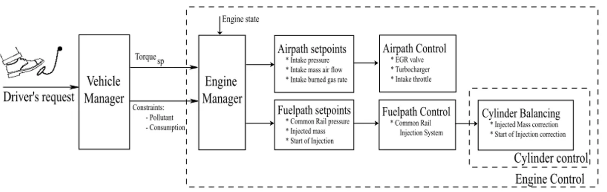
Dans le chapitre 2, nous décrivons la structure de contrôle pour moteur Diesel développé à l’IFP. Nous examinons l’impact de chaque actionneur sur le processus de combustion. La structure de commande dite, "en couple", visant à contrôler le couple fourni par le moteur, est étudiée. Nous détaillons les étapes qui permettent de calculer les consignes des actionneurs, étant donnée une demande en couple du conducteur fixée. Ensuite,
4 PRÉSENTATION DE LA PARTIE I
nous donnons une interprétation de l’évolution des caractéristiques du mélange aspiré dans le cylindre (masse totale, composition et température), lorsque les consignes des actionneurs varient. En résumé, nous étudions les effets des commandes sur le processus de combustion et sur les performance du moteur. Ces performances sont exprimées en terme de bruit, de couple fourni et d’émissions polluantes. Enfin, nous nous intéressons à la gestion de l’injection. Le problème considéré se résume à deux questions : "quel est le moment le plus opportun pour injecter le carburant dans le cylindre?" et "quelle quantité doit-on en injecter?" En particulier, nous expliquons comment améliorer les performances du moteur. Moduler le temps d’injection et utiliser l’avance à l’injection permettent de réduire le bruit et les émissions polluantes tout en fournissant le couple demandé. Nous présentons des résultats de simulations obtenus avec le logiciel AMESim [63], qui illustrent les effets des variables de contrôle sur le processus de combustion.
Le contrôle de la combustion en mode HCCI est complexe. De petites différences entre le mélange dans le cylindre (air- gaz brûlés - carburant) et le mélange de référence peuvent avoir des conséquences sérieuses: bruits, augmentation des émissions de polluants et même extinctions d’un ou plusieurs cylindres. Dans le chapitre 3, nous proposons de séquencer le problème général du contrôle de la combustion en trois sous problèmes.
Le contrôle de la boucle d’air : Dans un premier temps, nous cherchons à contrôler les masses aspirées dans le cylindre (air frais et gaz brûlés).
Le contrôle cylindre à cylindre : Il s’agit du problème d’équilibrage entre les cylin-dres en dépit de la variabilité des éléments techniques constitutifs (notamment les injecteurs). En effet, alors que chaque injecteur reçoit la même consigne, on constate que tous les cylindres n’ont pas le même comportement.
Le contrôle de la boucle de fuel : Enfin, pour garantir les caractéristiques du mélange dans le cylindre il est nécessaire de ralentir la dynamique de la boucle de fuel pour l’adapter à celle de la boucle d’air (typiquement dix fois plus lente).
Comme nous le montrons expérimentalement sur un moteur HCCI, les deux premiers problèmes sont essentiels au fonctionnement du moteur. Le troisième n’est pas primordial. En revanche ne pas le résoudre revient à accepter un niveau élevé de bruit et d’émission de polluants en transitoire. Ce qui est en contradiction avec une utilisation industrielle. C’est la prochaine étape de notre travail.
PRESENTATION OF PART I
This part describe the main engine dynamics and the key variables influencing the combustion process. The Diesel engine combustion consists of several steps. First of all, gas (air and burned gas) are aspirated into the cylinder. Then, the compression increases the temperature and the pressure in the cylinder. Fuel is injected and finally, after the auto-ignition delay, combustion occurs. This simplified description points out the main variables affecting the combustion. To control the combustion, it is desired to know what is aspirated into the cylinder (i.e. the total mass of gas and its composition) and how much and when fuel should be injected. Most of the material contained in this part can be found in the classic reference [58].
Chapter 1 is dedicated to the description of the Diesel engine. Step by step, the combustion process is presented. A model of heat release is proposed, stressing the main variables impacting on the combustion process. Then, we expose the limitations of the “classic” Diesel combustion in terms of pollutant emissions. These are inconsistent with future pollutant emissions (such as Euro V). Naturally, this point justifies efforts towards realizing a cleaner combustion. We explain the role of the Exhaust Gas Recirculation (EGR) in the context of the HCCI combustion (Homogeneous Charge Compression Ignition). EGR allows a better mixing and dilution in the cylinders and leads to a combustion with less pollutant formation.
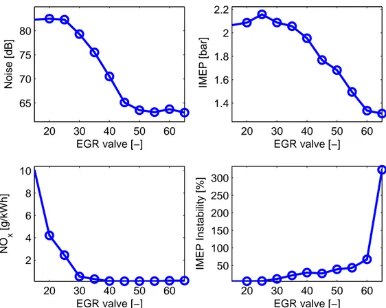
Chapter 2 describes the main effects of each actuator on the combustion process. We expose the torque control structure usually found in commercial-line engine. More precisely, we explain the several steps to turn the driver’s torque demand into actuator set points. The impact of the air path actuators (EGR valve and turbocharger) on
6 PRESENTATION OF PART I
the gas aspirated into the cylinder (total mass aspirated, composition, temperature) is investigated. We detail their effects on the cylinder pressure and the engine performance in terms of noise, torque production, and, pollutant emissions. Finally, we describe the
injection system and explain how sophisticated injection timing can produce lower NOx.
Also, we explain the impact of the injection timing and quantity on combustion in terms of noise, torque production, and pollutant emissions.
Chapter 3 presents several control issues to be solved in order to run the engine over an usual operating range including steady–states and transients. Three main problems are defined. The first problem is the air path control. Here, it is desired to control the masses (fresh air and burned gas) in the cylinders. We describe the particularities of this nonlinear, coupled, and non minimum phase dynamics. The second problem is cylinder balancing. The goal is to guarantee that all the cylinders have the same combustion. Even with identical actuator set points, the cylinders do not exactly have the same combustion. This unbalance leads to a lower overall efficiency and also increases higher pollutant emissions. Such unbalance is mainly seen at low load operating points where we are running with high burned gas rate and low fuel injection quantity. These conditions precisely correspond to the HCCI combustion mode and lead to malicious noise and possible stall. Finally, the last problem we consider is the fuel path control and its adaption to slower air path dynamics.
CHAPTER 1
FROM CONVENTIONAL DIESEL TO HCCI
ENGINE
Chapitre 1. —
D’un moteur Diesel vers un moteur HCCI
Dans ce chapitre, nous décrivons les différents éléments d’un moteur Diesel. Nous présen-tons les différentes étapes du processus de combustion. Un modèle de dégagement de chaleur est proposé. Dans ce modèle apparaissent les variables principales intervenant sur la com-bustion. Ensuite, nous expliquons les problèmes induits par le mode de combustion Diesel, principalement en terme d’émissions polluantes. Nous détaillons pourquoi il est nécessaire de recourir à la combustion dite homogène (HCCI Homogeneous Charge Compression Ig-nition) qui permet de limiter les émissions polluantes. Une grande partie des éléments de ce chapitre a été publiée dans [58].
1.1. Introduction
After carbon dioxide (CO2) was identified as a greenhouse gas contributing to global
warming, Diesel engines have emerged as an alternative to gasoline engines due to their
low fuel consumption and low CO2 emission. While carbon monoxide (CO) emissions are
negligible in CI engines due to lean operation and emissions of unburnt hydrocarbons (HC)
that can be handled with oxidation catalysts, the emissions of oxides of nitrogen (NOx)
and particulate matter (PM) are a main concern.
First of all, we present a “conventional” Diesel engine. A scheme of a 4-cylinder engine is presented in Figure 1.1. We describe the various parameters influencing the combustion and the different components of the engine (turbocharger, injection system, . . . ). Then, we explain the limitation of Diesel combustion concerning pollutant reduction and the need
8 CHAPTER 1. FROM CONVENTIONAL DIESEL TO HCCI ENGINE
Figure 1.1. 4-cylinder Diesel engine scheme.
for a cleaner combustion. We explain the role of the exhaust gas recirculation (EGR) on the combustion and detail how the homogeneous combustion (HCCI combustion) limits the pollutant emissions. Most of the material contained in this chapter can be found in the classic reference [58].
1.2. Diesel engine
1.2.1. Diesel engine combustion. — The combustion process is divided into a
pre-mixed phase and a diffusion phase. During the pre-pre-mixed phase, the fuel is injected and mixed. After a small time delay, the mixture ignites and burns under premixed conditions. During the diffusion phase, the remaining part of the fuel that is injected burns at a rate
1.2. DIESEL ENGINE 9
controlled by the mixing of the fuel with the surrounding air. To ensure good mixing with the air, the injected fuel spray has to break up in small droplets. This is achieved by high injection pressures (ranging from 1000 to 2000 bar, depending on the injection system) and small orifices in the injector nozzle. The power output is controlled by regulating the fuel flow while the air flow is un-throttled, resulting in a varying air-fuel ratio. The power output limit is determined by the smoke limit. At this limit, there is too much fuel to properly mix with the available air, so the fuel is only partially burned, resulting in a large amounts of soot emissions or smoke. Power is also limited by the amount of air aspirated by the engine because combustion is lean. Therefore, Diesel engines are often supercharged. In more details, the Diesel combustion process from start of injection to the end of combustion can be divided into several steps as explained in [58]. We now detail these phases.
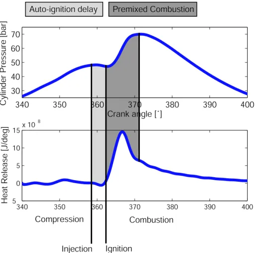
1.2.1.1. Steps of the combustion process. — These steps are represented in Figure 1.2. 1.2.1.1.1. Initial conditions. — During the intake, gas from the intake manifold (fresh air and burned gas) are aspirated and mixed with the residual gas still present in the cylinder. Compression increases the cylinder pressure and temperature.
1.2.1.1.2. Fuel Injection. — First, fuel is injected by the injection system into the cylinder at the end of the compression stroke, right before the desired start of combustion. The liquid fuel, usually injected at high velocity by the high pressure common rail injection system, atomizes into small drops and penetrates into the combustion chamber.
1.2.1.1.3. Vaporization and mixing. — Then, the fuel vaporizes and partially mixes with the gas previously trapped into the cylinder (these gas are at high temperature and high pressure due to the compression phase). The mixing rate depends on both the turbulence in the combustion chamber and on the air entrainment into the spray. Turbulence is caused by the instability of the shear layer and the high velocity of the fuel. Since mixing limits the combustion rate, the maximum speed is limited by the mixing rate.
1.2.1.1.4. Auto ignition delay. — The ignition delay is the time between the start of injection and the start of ignition. The magnitude of this delay is determined by the time needed for evaporation and mixing of the fuel and air. This delay is characterized by the
chemical delay time, τai, which depends on the intake pressure and temperature. The
combustion occurs when the integration of the delay (1.1) reaches the value 1: Z τai
0
10 CHAPTER 1. FROM CONVENTIONAL DIESEL TO HCCI ENGINE 340 350 360 370 380 390 400 30 40 50 60 70
Cylinder Pressure [bar]
Crank angle [˚] 340 350 360 370 380 390 400 5 0 5 10 15x 10 8
Heat Release [J/deg]
Injection Ignition
Compression Combustion
Auto-ignition delay Premixed Combustion
Figure 1.2. Experimental conventional Diesel combustion with the several steps of the combustion process. Top: Cylinder pressure. Bottom: Heat release.
where A and n are the parameters of the auto-ignition delay, Tact is the activation
temper-ature defined for the auto ignition. Tcyl and Pcyl are respectively the average temperature
and pressure in the combustion chamber.
1.2.1.1.5. Ignition and combustion. — Finally, since air temperature and pressure are above the fuel ignition point, spontaneous ignition of portions of the already-mixed fuel and air occurs after the auto ignition delay. The combustion starts with a premixed-type combustion. This premixed combustion is characterized by a strong heat release. It is due to the whole combustion of this mixing formed during the delay. Ignition continues until the desired amount of fuel has entered the cylinder. Atomization, vaporization, and fuel-air
1.2. DIESEL ENGINE 11
mixing continue until all fuel has passed through each process. In addition, mixing of the air remaining in the cylinder with burning and already burned gas continues throughout the combustion and expansion process.
Combustion is a complex phenomena. Nevertheless, a lot of effort was done on the modelling. This provides guidelines and physical understanding on what is happening in the cylinder. In the next subsection, we describe a modelling approach of the combustion stressing out the main variables influencing the combustion.
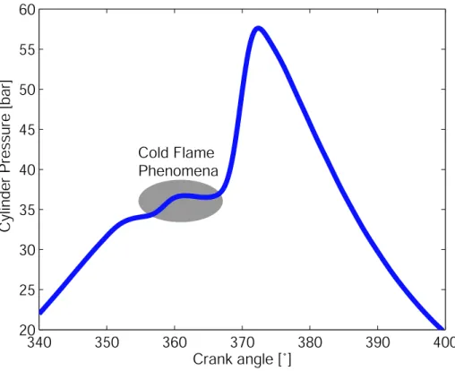
1.2.1.2. Combustion modelling. — For conventional CI combustion mode, the injection rate is the main parameter which controls the turbulent scale and energy level in the chamber. It mainly controls the combustion process. In system simulation modelling [40, 41, 10, 6], the conventional CI combustion can be defined using a simple diffusion flame and because the injection occurs near the combustion TDC, the auto-ignition delay is short and can be neglected [41]. This type of model is suitable for single injection, but, in the case of multi-injections, the introduction of an auto-ignition model becomes important [10]. Moreover, compared with the conventional CI combustion mode, the pre-mixed part of the combustion can not be neglected any more and when the EGR rate increases, a cold flame phenomenon also appears [40, 10, 102, 97]. A representation of this cold flame on an experimental HCCI combustion is represented in Figure 1.3.
As presented below, for the Diesel conventional CI combustion mode, many studies [40, 10, 61] have shown that the diffusion combustion is the main physical phenomenon in the combustion process. This model is based on the works of Chmela [40, 41] and Jaine [64]. In this approach, the Combustion Heat Release Rate (CHRR) is related to the available
vapor fuel mass in the chamber Mf. This quantity can be computed as the difference
between the evaporated fuel mass Mf,v and the burned fuel mass. A second assumption is
that the local density of the turbulent kinetic energy determines the rate of mixing of the fuel vapor and fresh air and thus the CHRR. In conventional Diesel engines, the essential source of turbulent kinetic energy is the kinetic energy introduced by the fuel injection due
to sprays. Using these assumptions, the CHRR Q is calculated using 2 functions f1 and
f2, as presented in Equation (1.2)
dQ
dα = Cmodef1(Mf, Q)f2(k, V ) (1.2)
where Mf is the available vapor fuel mass, Q is the CHRR, k is the turbulent kinetic
energy and V is the combustion chamber volume. The functions f1 and f2 are
f1(Mf, Q) = Mk− Q LCV and f2(k, V ) = e Crate √k √ V3 (1.3)
12 CHAPTER 1. FROM CONVENTIONAL DIESEL TO HCCI ENGINE 340 350 360 370 380 390 400 20 25 30 35 40 45 50 55 60
Cylinder Pressure [bar]
Crank angle [˚] Cold Flame
Phenomena
Figure 1.3. Experimental HCCI Diesel combustion. Cylinder pressure trace with the cold flame phenomena.
with LCV the lower calorific value, Cmode and Crate are the model parameters to fix the
effect of turbulence on the combustion process. To introduce the effects of the EGR rate on the combustion process, Equation (1.2) is modified as
dQ
dα = Cmode(1 − Xbg)
βf
1(Mf, Q)f2(k, V ) (1.4)
where Xbg is the molar fraction of burned gas. Because increasing the EGR rate decreases
CHRR, β must have a positive value.
The physical factors that affect the development of the fuel vaporization and the air charge state impact on the combustion by modifying torque production, noise, pollutant production, and ignition delay. The air charge depends on the quantity of gas entering into
the cylinder during the compression (Masp,air and Masp,bg) and their temperature (Tasp,gas),
the fuel vaporization depends on the injection timing and quantity (tinj and Minj). The
1.2. DIESEL ENGINE 13
elements are detailed in subsection 1.2.2. The injection system controlling the fuel path is explained in subsection 1.2.3.
1.2.2. Air path elements. — The air loop circuit has to be suitable for both running
conditions at full load and at partial load. Because air capacity is an important constraint on the amount of fuel that can be burned in the Diesel engine, and therefore on the engine power, turbocharging is used extensively. The air path system consists of two parts: the turbocharger and the Exhaust Gas recirculation (EGR).
The turbocharger is a turbine driven by the exhaust gas and connected via a common shaft to the compressor, which compresses the air in the intake. Figure 1.4 represent a
Figure 1.4. Turbocharger scheme from [45].
scheme of a turbocharger. The rotational speed of the turbocharger shaft Nturb can be
derived from a power balance between the turbine Pturb and the compressor side Pcomp
d dt(
1 2JturbN
2
turb) = Pturb− Pcomp
where Jturb is the inertia of the turbocharger.
1.2.2.1. Compressor. — In order to derive an equation for the compressor power, the first law of thermodynamics is applied. It states that (neglecting heat losses) the compressor
14 CHAPTER 1. FROM CONVENTIONAL DIESEL TO HCCI ENGINE
enthalpy by
Pcomp = Dair(hcomp− hamb) = Daircp(Tcomp− Tamb)
where Tamb and Tcomp are the ambiant and the compressor temperature respectively. The
second equality assumes constant specific heats. Assuming that the compression process is isentropic, the compressor power reads
Pcomp = DaircpTamb 1 ηcomp µ (Pcomp Pamb )γ−1γ − 1 
where ηcomp is the compressor efficiency, Pamb and Pcomp are the ambiant and compressor
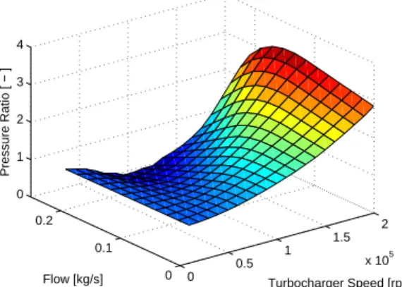
pressure and γ the specific heat ratio. In order to calculate the compressor power, the compressor efficiency and mass flow have to be known. These variables are highly nonlinear functions of the pressure ratio across the compressor and the turbocharger shaft speed. Those variables are represented in Figures 1.5 and 1.6.
0 0.5 1 1.5 2 x 10⁵ 0 0.1 0.2 0 1 2 3 4 Turbocharger Speed [rpm] Flow [kg/s] Pressure Ratio [ − ]
Figure 1.5. Compressor map. Pres-sure ratio at the compressor w.r.t. the flow through the compressor Dairand
the turbine crankshaft speed Nturb.
0 0.5 1 1.5 2 x 10⁵ 0 0.1 0.2 0.30 0.2 0.4 0.6 0.8 Turbocharger Speed [rpm] Flow [kg/s] Efficacity [−]
Figure 1.6. Compressor map. Effi-ciency ηcomp at the compressor w.r.t.
the flow through the compressor Dair
and the turbine crankshaft speed Nturb.
1.2.2.2. Turbine. — Similarly, the turbocharger power is related to the mass flow through
the turbine Dturb and the total change of enthalpy. This results in
Pturb = DturbcpTpostηturb µ
1 − (PPpost exh
)1−γγ 
1.2. DIESEL ENGINE 15
where ηturb is the turbine efficiency, Tpost and Ppost are the temperature and pressure after
the turbine, Pexh the exhaust manifold pressure and γ the specific heat ratio. Again, the
turbine flow Dturband isentropic efficiency ηturb are mapped versus the pressure ratio across
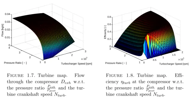
the turbine and the turbocharger shaft speed. However, these variables also depend on the geometry of the turbocharger. They replace the conventional waste gate in order to avoid overspeeding at high engine loads without sacrificing the low load performance. Very large amount of data are needed to obtain reasonably accurate fit. Those variables are represented in Figures 1.7 and 1.8. We control the geometry of the turbine (VGT) and its
0 1 2 3 x 10⁵ 1 2 3 4 0 0.01 0.02 0.03 0.04 Turbocharger Speed [rpm] Pressure Ratio [ − ] Flow [kg/s]
Figure 1.7. Turbine map. Flow through the compressor Dexh w.r.t.
the pressure ratio PpostPexh and the tur-bine crankshaft speed Nturb.
0 0.5 1 1.5 2 x 10⁵ 1 2 3 0 0.2 0.4 0.6 0.8 Turbocharger Speed [rpm] Pressure Ratio [ − ] Efficacity [−]
Figure 1.8. Turbine map. Effi-ciency ηturb at the compressor w.r.t.
the pressure ratio PpostPexh and the tur-bine crankshaft speed Nturb.
discharge with a waste-gate. This leads to a control of the turbocharger crankshaft speed control and then the intake air flow control.
1.2.2.3. Exhaust Gas Recirculation. — The Exhaust Gas Recirculation (EGR) allows to recirculate gas from the exhaust manifold to the intake manifold. The recirculation of exhaust gas through an EGR valve into the intake manifold where it dilutes the incoming
fresh air is a well established and efficient means of reducing in-cylinder NOx emissions
(The effects of EGR on the combustion is detailed in subsection 1.4.1). The flow through
the EGR pipe, Degr, is driven by the pressure ratio between the exhaust manifold
pres-sure, Pexh, and the intake manifold pressure Pintand controlled by an EGR valve. Assuming
that no mass is accumulated in the EGR system, it can be modelled with static equations rather than with differential equations. The flow through the EGR valve is determined by
16 CHAPTER 1. FROM CONVENTIONAL DIESEL TO HCCI ENGINE
the standard orifice flow equation [58] Degr = Segr Pexh √ RTexh s 2γ γ − 1¡p 2 γ r − p γ+1 γ r ¢
with the pressure ratio pr = max{PexhPint, (γ+12 ) γ
γ−1} in order to describe subsonic as well as
choked EGR flow. The effective area Segr is identified as a quadratic polynomial of the
normalized valve lift Oegr. As described in 1.4.1, the recirculation of exhaust gas raises
Figure 1.9. EGR high pressure scheme.
the temperature of the inlet charge and, consequently, leads to a higher flame temperature
resulting in higher NOx emissions which is the opposite of the initial goal of the EGR. In
order to minimise the inlet charge temperature effect, the recycled exhaust gas need to be cooled. The EGR pipe is equipped with a cooler in order to reduce the temperature of the gas coming from the EGR as represented in Figure 1.9.
1.2.3. Fuel path elements. — The Common Rail fuel injection system is widely used
nowadays in modern Diesel engines. The main benefits of the system is that it allows to inject the fuel in the cylinder at a very high pressure which implies a better vaporization and mixing, and then a better combustion. Moreover, contrary to pump-injectors, it decouples the pressure generation from the injection timing and duration. These processes
1.2. DIESEL ENGINE 17
Figure 1.10. Scheme of the Common Rail Injection system from [44].
are independent of each other and adjustable over a wide range of operating conditions. The large amount of freedom of injection parameters has opened new opportunities to improve combustion characteristics. The Common Rail Diesel Injection System (see Figure 1.10) is an accumulator injection system. It provides more flexibility than any previous injection system, but it also needs to handle much higher pressure. The high pressure circuit contains a high-pressure pump, a pressure-control valve, a high pressure accumulator (the rail) with a rail-pressure sensor, high pressure connection lines and the injectors (see Figure 1.10). The high-pressure pump forces the fuel into the rail and generates a maximum pressure of nearly 2000 bar. There is one injector for each cylinder and the injectors contain a solenoid or piezo valve which receives a current signal from the ECU to control its position (open or closed). Every time an injection occurs, fuel is aspirated from the rail. This technology enables very short injection, i.e. it is possible to do several injections for the same combustion. We will see in section 2.4 that this possibility enables significant pollutant emission reduction. The pressure control valve attempts to keep the pressure
18 CHAPTER 1. FROM CONVENTIONAL DIESEL TO HCCI ENGINE
at the desired level. This control is based on measurements from the rail pressure sensor. With the common rail, one can control the injection timing and the start of injection of fuel in all the cylinders.
1.3. Why HCCI combustion?
From its principle, the Diesel engine is placed at the first rank of the converters of energy at low fuel consumption and minimal carbon dioxide discharge. Until now, these advantages were counterbalanced by emissions of oxides of nitrogen high, a disadvantage difficult to surmount because subordinate to the same principles of Diesel combustion, which are precisely favorable to the output. Facing the pollutant norms, Diesel engine has to evolute to face the new pollutant norms.
1.3.1. Pollutant norms. — Increasingly stringent pollution standards norms have spurred a broad interest in the reduction of global engine emissions as we can see in
Table 1.1. Emissions of nitrogen oxides (NOx) and particulate matter (PM) from Diesel
Passager Cars PM (mg/km) NOx (g/km) HC (g/km) HC+NOx
Diesel Petrol Diesel Petrol Diesel Petrol Diesel Petrol
EURO I (1992-93) 140 - - - .97 .97
EURO II (1996) 80 - - - .7 .5
EURO III (2000) 50 - .5 .15 - .2 .56
-EURO IV (2005) 25 25 .25 .08 - .1 .3
-EURO V-(2008) 2.5 2.5 .08 .08 .05 .05 -
-Table 1.1. EU emission standards for passenger car including proposal for 2008. Source: ACID NEWS No 3, September 2004.
vehicles are higher than for petrol vehicles. New findings about the harmful health effects of particulates have called for significant reductions in emission limits from Diesel vehi-cles. The draft Euro V limits would reduce emissions of particulates from diesel cars by
80% compared to Euro IV. Achieving high reduction of NOx/PM for “classical” CI engine,
without increasing too much CO2 emission seems impossible. Lately, two strategies have
emerged to face this problem: post-treatment and direct combustion emissions reduction. The three way catalytic converter (TWC) removes CO and HC efficiently at lean air fuel
1.3. WHY HCCI COMBUSTION? 19
Research has focused on the catalytic decomposition of NOx, but, up to now, a suitable
catalyst with a significant activity in real exhaust gas has not been identified. A promising
technique under investigation for NOxremoval is a LNT (Lean NOxTrap) located after the
TWC in the exhaust system. Under lean operating conditions, the NOx is accumulated or
“trapped” in the LNT. The trapped NOx is periodically released or “purged” by operating
at a stoichiometric or rich air fuel ratio. The released NOx is reduced to N2 by CO and
H2 already present in the exhaust gaz. By the same way, a particulate filter is used to
“trap” the particulates. For Diesel engines, equipments required by post-treatment and implementation issues usually carry high cost premiums. An alternative is to use a cleaner combustion mode. Therefore, the Highly Premixed Combustion mode (HPC), including Homogeneous Charge Compression Ignition (HCCI), has become of major interest in recent years. This combustion principle consists in preparing a highly diluted by burned gas air/fuel mixture, in achieving its simultaneous ignition, and in precisely controlling the combustion for the best performance in terms of efficiency and pollutant emissions. HCCI or HPC combustion takes place in a more or less homogeneous way throughout the bulk
of the mixture, where thermal NOx formation and soot production are known to be much
lower than with typical conventional Diesel combustion diffusion flame.
1.3.2. Toward HCCI combustion. — In order to get good performances in terms of torque production, consumption and pollutant emission, it is important to properly mix fuel and air before starting combustion. Historically, the first development axis was to use the common rail for increasing the combustion period. Multi-injections are used to expand the combustion in order to decrease the peak pressure and temperature. While the aimed
low temperature combustion allows to reduce drastically the NOx formation, and, in some
cases PM formation, this technique is seriously flawed. In particular,
– It is necessary to avoid wall impingement and promote fuel vaporisation and Air/Fuel mixing to limit PM and HC emissions while preventing oil dilution.
– Stability at high load is problematic: operating conditions at high Fuel/Air equiv-alence ratio are limited by combustion stability, excessive heat release, knock and noise.
– Stability at low load is also problematic: operating conditions at high BGR are limited by combustion stability, cylinder to cylinder combustion variability and stall.
To summarize, the HCCI combustion mode permits to have very low NOx and PM
emis-sions but it favors HC and CO emisemis-sions and increases noise level and combustion insta-bility.
20 CHAPTER 1. FROM CONVENTIONAL DIESEL TO HCCI ENGINE
1.4. HCCI combustion properties
The defining characteristic of HCCI is that the ignition occurs at several places at a time which makes the fuel/air mixture burn nearly simultaneously. There is no direct initiator of combustion. To obtain an homogeneous mixture, the main characteristics is to dilute the air charge with a very large amount of Exhaust Gas Rate (EGR) in the combustion chamber. Recirculating burned gas can be achieved in several way. The first one is to use Variable Valve Activation (VVA) leading to internal EGR. The second possibility is to use EGR pipes, taking gas from the exhaust line into the intake line.
In this section, we describe the effect of exhaust gas recirculation on the pollutant formation and noise reduction. Then, we present the impact on the architecture of the engine.
1.4.1. On the use of high Exhaust Gas Recirculation. — The recirculation of
exhaust gas through an EGR valve into the intake manifold (where it dilutes the incoming
fresh air) is a well established and efficient means of reducing in-cylinder NOx emissions.
On the other hand, the reduction of NOx occurs at the expense of higher PM emissions
(due to lower thermal efficiency). In [82, 101, 83, 84, 86, 85] separated several possible
effects of EGR on the in-cylinder NOx production are presented.
1.4.1.1. Effect on the dilution. — The change of in-cylinder oxygen by exhaust gas reduces the availability of oxygen during the combustion. This lowers the temperature of the whole combustion process in the premixed burn as well as in the diffusion flame, where most of
the NOx are created. In fact, the combustion still occurs in a region where the ratio of fuel
and oxygen is close to the stoichiometric ratio but now with exhaust gas acting as a diluent.
Notice that the dilution effect is the most influential parameter in the NOx reduction by
exhaust gas recirculation. While the dilution of the inlet charge has only a minor effect on the thermal efficiency of the engine, particulate emissions increase significantly while decreasing inlet charge oxygen.
1.4.1.2. Effect on the inlet charge temperature. — The recirculation of exhaust gas raises the temperature of the inlet charge and consequently leads to a higher flame temperature
resulting in higher NOx emissions (although less significantly than the dilution effect).
This is a EGR drawback. Moreover, it is observed that an increase in inlet temperature results in substantially higher PM emissions (especially soot). In order to minimise the inlet temperature, the recycled exhaust gas are cooled. The EGR pipe is equipped with a cooler in order to reduce the temperature of the gas coming from the EGR. High cooling
1.4. HCCI COMBUSTION PROPERTIES 21
of the EGR allows to extend the HCCI operating range. Nevertheless, when high EGR cooling is applied, condensation in the EGR pipe can appear which limit the temperature of the EGR.
1.4.1.3. Effect on the ignition delay. — While the increase of the inlet charge temperature shortens the ignition delay, the lower oxygen availability increases it. The net effect of EGR is an increase of the ignition delay. This increase potentially affects the combustion by boosting the fuel fraction burnt during the premixed burn and by shifting the auto-ignition towards the combustion chamber wall, however, the lower oxygen availability due to the dilution effect actually reduces the peak rate of premixed burning. This reduced burning rate and the delay of the combustion towards the expansion stroke reduces peak temperatures and pressures and the time the combustion gas spend under these conditions.
Thereby, NOx emissions are reduced (although significantly less than the dilution effect)
at the expense of PM emissions and thermal efficiency. Obviously, the ignition delay effect can be compensated (partially) by adjusting the injection timing.
1.4.2. Impact on the EGR on the engine architecture. — The main drawback of Diesel engine is the low power density (since the mixture is always lean, less fuel can be induced in a given cylinder, at atmospheric conditions; in addition, engine top-speeds are lower due to mechanical limitations). This can quite easily be eliminated by supercharging the engines (forcing more air into the cylinder and thus allowing more fuel to be burned in the same volume). At full load, the output torque and power specifications fixe the upper limit of the air mass flow required by the engine according to the geometric compression ratio. The turbocharger choice is defined by the power specification.
When engine load increases in the HPC combustion mode, EGR and fresh air mass flow increase requires high intake pressure which can make the compressor operate near the limit operating range at low engine speed (EGR act as a discharge for the turbocharger). Small compressor size has then to be preferred. But, future target standards for the maximum output power impose an adapted air flow leading to larger compressor size. So, the compressor has to be compatible with both high and low engine speeds. Compressor choice is quite guided by turbocharger development progress which leads to enlarged the compressor operating range. On the other hand, the weak exhaust gas energy available for the turbine at low engine speed, which is further reduced by a high EGR rate, makes turbine efficiency a key parameter to consider for the choice of a turbocharger.
There are different ways to increase the required compressor work. A two stage turbo-charger can be used to obtain a higher compression ratio, which allows more air to be
22 CHAPTER 1. FROM CONVENTIONAL DIESEL TO HCCI ENGINE
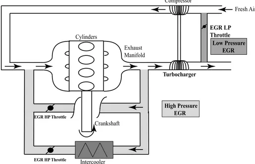
introduced in the engine for a given burned gas mass flow. A variable geometry compressor is also an interesting way to develop by tuning continuously the compressor map to the engine running point. E-boosts and turbocharger electrical assistance are other solutions to compensate the lack of exhaust energy when gas temperature is low. Two means to fulfil the air loop specifications are now described. They are "Conventional air loop circuit" or "High Pressure EGR" and "Modified air loop circuit" or "Low Pressure EGR". Due to the high burned gas mass flows required by engines running in the HPC mode, the EGR circuit has to be designed in both cases to allow a high EGR rate while maintaining low pressure losses which increase fuel consumption. A scheme of the location of the High Pressure EGR and Low Pressure EGR is presented in Figure 1.11.
Crankshaft Cylinders Turbocharger Compressor High Pressure EGR Fresh Air EGR HP Throttle Exhaust Manifold EGR LP Throttle Low Pressure EGR
EGR HP Throttle Intercooler
Figure 1.11. Schematic view of the High Pressure EGR and Low Pressure EGR on a Diesel engine.
1.4.2.1. High Pressure EGR. — In this EGR circuit layout, burned gas are picked up upstream of the turbine and mixed to fresh air downstream of the compressor. So, only fresh air passes through the compressor. In that case, EGR acts as discharge for the turbocharger. Because the EGR rate used in highly premixed combustion is significantly higher than usually considered in conventional combustion, advanced development of a specific cooler and valve are required both for the permeability aspect and for the fouling
![Figure 1.10. Scheme of the Common Rail Injection system from [44].](https://thumb-eu.123doks.com/thumbv2/123doknet/2881707.73061/44.918.202.710.170.563/figure-scheme-common-rail-injection.webp)