OATAO is an open access repository that collects the work of Toulouse
researchers and makes it freely available over the web where possible
Any correspondence concerning this service should be sent
to the repository administrator:
tech-oatao@listes-diff.inp-toulouse.fr
This is an author’s version published in:
https://oatao.univ-toulouse.fr/
2
6082
To cite this version:
Zielinski, Margot
and Cassayre, Laurent
and Destrac, Philippe
and
Coppey, Nicolas and Garin, Gilles and Biscans, Béatrice
Leaching
-mechanisms of industrial powders of spent nickel metal hydride batteries in a pilot
scale reactor. (2020) ChemSusChem, 13 (3). 616-628. ISSN 1864-5631.
Official URL:
https://doi.org/10.1002/cssc.201902640
Leaching Mechanisms of lndustrial Powders of Spent
Nickel Metal Hydride Batteries in a Pilot-Scale Reactor
Margot Zielinski}
a, bJ Laurent Cassayre,l
al Philippe Destrac,l
al Nicolas Coppey,lbl Gilles Garin,lbl
and Béatrice Biscans*1a1
ln view of a sustainable recycling process, the leaching mecha nisms of nickel and rare-earth elements (REEs) contained within industrial samples of spent nickel metal hydride battery powders were investigated in HCI and H2SO.., under mild tem perature (25-60 °C) and pH (3-5.5). First, in-depth characteriza tion of the heterogeneous battery powder was carried out with powder XRD, SEM, electron probe microanalyzer wave length-dispersive spectroscopy (EPMA-WDS) quantitative analy ses of individual particles, and inductively coupled plasma opti cal emission spectrometry (ICP-OES) elemental analysis. An
un-Introduction
Securing access to specialty metals required for high-per formance technologies and energy materials has raised envi ronmental and economic concerns in the past decade. Avoid ing risks of supply shortages has become a major challenge for highly import-dependent economies, such as the EU.111 This is
particularly true for light rare-earth elements (REEs), for which China supplies over 95 % of the world's production, according to the 2017 European Commission report on Critical Raw Mate rials.111 Developing traditional mine production of such critical
minerais in the EU depends on long-term investment projects that are not flexible enough towards rapid changes in market demands.111 On the other hand, recycling of waste electric and
electronic equipment (WEEE) or renewable energy materials in the EU can serve as an attractive secondary source of raw ma terials. For instance, the inner content of nickel metal hydride (NiMH) batteries, which are mainly used for hybrid or pure electric vehicles (HEV or PEV), consists of about 50 wt% nickel12I and 15 wt% REEs.13I More than 1.8 million HEV battery
units were sold worldwide in 2016}41 with an average battery
collection rate of 44% in the EU that same year,15I and thus, as
suring a significant feed for the recycling market. However, the
(a] M. Zielinski, Dr. L. Cassayre, P. Destrac, Dr. B. Biscans Laboratoire de Génie Chimique
Université de Toulouse, CNRS, INPT, UPS
Toulouse (France)
E-mail: beatrice.biscans@toulouse-inp.fr (b] M. Zielinski, Dr. N. Coppey, Dr. G. Garin
Société Nouvelle d'Afflnage des Métaux (S.NAM.) Viviez (France)
usual result is the identification of particles that exhibit a core shell structure, which is related to anode active mass aging mechanisms. Then, a leaching study in a 10 L pilot-scale reac tor demonstrated the selective dissolution of REEs, with re spect to nickel, at pH 3, which is attributed to 1) the kinetic in hibition of nickel metal dissolution, and 2) the specific core shell structure of aged mischmetal particles. Furthermore, the use of H2S04 led to coprecipitation of lanthanide-alkali double
sulfates and nickel salts.
contribution of recycling to the market demand for critical ma terials is still relatively low because it is not yet technically nor economically feasible at the industrial scale.16I As a result, the
end-of-life recycling rate of REEs is below 3%11·71 and the end
of-life recycling input rate of nickel is only 25%.161 The 50 wt%
recycling efficiency target to be achieved for NiMH batteries, as described by the European Directive (2006/66/EC), makes it necessary for industries to develop more efficient and sustain able recycling schemes, and opens up new possibilities for urban mining.181
NiMH batteries are made up of four main components: an iron- or aluminum-based outer casing; anode and cathode cur rent collectors, upon which active electrode powders are de posited by using binders; an alkaline electrolyte, such as KOH; and a microporous polymer separator.19•121 The cathode current
collector consists of a dense metallic nickel mesh, whereas the cathode active mass is made of spherical particles of either nickel hydroxide �-Ni(OH)2 or oxyhydroxide NiO(OH), depend
ing on the state of charge of the batteryP3· 141 The anode typi
cally contains a nickel-plated steel support as the current col lector131 and an active mass consisting of a hydride alloy of
varying compositions. The structure of hydrogen storage alloys can either be ABs, in which A= La, Nd, Pr, Ce, or Y and B= Ni,
Co, Mn, or Al; AB2, in which A=Ti or Zr and B= Ni, Co, Mn, Al,
V, Cr, or Sn; or A2�, in which A=Nd or Mg and B=Ni or
AIY3·15I Such an intricate battery composition highlights the
need for advanced recycling processes to recover the majority of valuable metal content.
Hydrometallurgical processes are the main alternative for re cycling NiMH batteries, in which battery powders are generally
leached in a minerai acid, such as HCl113. 16-231 (around 40% of
To a minor extent, a few researchers have studied the use of
HNO3,[13,29] carboxylic acids,[12,21] or ascorbic acid as leaching
agents, but these have not been considered in this study. It is crucial to control the leaching step because the content of dis-solved metals in solution will have a direct impact on subse-quent recovery methods, such as precipitation or solvent ex-traction. Most of the literature on the leaching of spent NiMH batteries focuses on the impact of various operating parame-ters, such as type and concentration of acid, temperature, time, mixing speed, and addition of an oxidant. A nearly total dissolution of nickel and REEs is commonly sought-after, and thus, requires the use of aggressive leaching conditions: either high working temperatures (70–95 8C) or high acid concentra-tions (8–12m). However, in view of more sustainable NiMH bat-tery recycling processes, it is interesting to find milder leaching conditions. Although recent studies have been carried out in this regard,[13,21,23]it is still necessary to better understand the
particle leaching mechanisms at stake.
Moreover, at the industrial scale, spent NiMH batteries un-dergo specific head–end steps before leaching, such as ther-molysis, milling, and sieving. Indeed, spent battery packs are first collected and sorted according to their type. Then they are processed through a heat treatment under a controlled at-mosphere (thermolysis) to remove volatile organic compo-nents and make the batteries electrically inert. The material is then milled and sieved to obtain a powder enriched in valu-able elements, such as nickel and REEs. These processing steps impact on both the chemical and physical properties of the starting material, and might consequently influence the leach-ing process. However, apart from a few studies,[10,12, 14,33]the
ini-tial material in most reports in the literature comes from man-ually dismantled batteries that have not gone through these pretreatment steps.
The aim of this work is, therefore, to provide a better under-standing of the leaching behavior of nickel and REEs from in-dustrial powders of spent NiMH batteries, the so-called black mass (BM) powder. The originality of this research lies in the fact that we have carried out in-depth particle characterization of a heterogeneous material with respect to that found at the industrial scale. The methodology applied for initial material characterization was then transferred to the analysis of solid leach residue, which was obtained from leaching experiments carried out in a 10 L pilot-scale reactor. Furthermore, to consid-er a more sustainable process at the industrial scale, we select-ed mild temperature (25 8C<T<60 8C) and pH (3<pH <5.5) operating conditions for the leaching experiments, in two acid media (HCl and H2SO4).
Results
BM powder characterization
An industrial sample of approximately 600 kg of mixed types of spent NiMH batteries was collected. The battery packs, which were composed of a mixture of anodes, cathodes, and casing materials, were processed at industrial facilities. They were dismantled, thermolyzed in an oven, crushed by knife
milling, and sieved at <1 mm. The resulting powder, BM, was carefully characterized before being used as a starting material for the leaching study.
Chemical composition and phase analysis
The average chemical composition of four samples of industrial BM powder from the same batch is provided in Table 1 (see the Experimental Section for all analytical details). The BM powder is mainly composed of 45.0 wt% Ni, approximately 15.9 wt% REEs (La, Ce, Nd, Pr), 13.1 wt% O, 5.4 wt% Co, and
2.4 wt% Mn. Although the contents of Co and Mn in the BM powder are significant and these metals have a noticeable eco-nomic value, herein we have chosen to report only results for the major elements Ni and REEs. The presence of K (2.2 wt%) is attributed to residual KOH electrolyte. Sodium is absent from the BM (below the detection limit), and traces of cadmi-um and lithicadmi-um are due to cross contamination from other types of batteries during the manual battery-sorting step. Ele-mental carbon (2.8 wt%) most likely comes from the residue of organic components formed during heat treatment of the bat-teries. A total chemical composition of 93.65 wt% is obtained; the missing mass can be explained by the fact that additional elements such as Y or Sm have not been analyzed and that a small quantity of BM could not be dissolved prior to elemental analysis.
The powder X-ray diffractogram (Figure S1 in the Supporting Information) provides evidence of the presence of Ni, NiO,
CeO2, and graphite as major phases. Minor phases include
Co3La2 and La7Ni16; other rare-earth-containing phases could
not be identified due to the detection limit of the technique.
Table 1. Average chemical composition [wt%] of the industrial BM sample powder.
Element Chemical composition [wt%]
Al 0.85 :0.01 Cd 0.83 :0.05 Co 5.45 :0.23 Cu 0.51 :0.03 Fe 2.90 :0.32 K 2.17 :0.07 Li 0.13 :0.01 Mn 2.37 :0.14 Na <detection limit Zn 1.56 :0.19 Ni 44.98 :0.69 La 8.72 :0.22 Ce 5.02 :1.09 Nd 1.68 :0.05 Pr 0.45 :0.01 O 13.1 :0.1 C 2.83 total 93.65
Local elemental particle characterization
Although local electron probe microanalyses (EPMA) infer that both the morphology and associated chemical composition of the BM particles are very heterogeneous, our observations lead us to propose a classification into five main categories of parti-cles.
P1-type particles observed and characterized by means of scanning electron microscopy energy-dispersive X-ray spectros-copy (SEM-EDX; not shown herein) consist of individual iron oxide and aluminum oxide particles, with a characteristic di-mension of about 30 mm, possibly originating from the outer casing of the battery.
As shown in Figure 1, zone 1, P2-type particles containing around 97 at% Ni were evidenced (Table 2). They come from the metallic nickel mesh of the cathode current collector and correspond to the nickel phase identified by means of powder XRD.
P3-type particles consist of circular porous particles, single or agglomerated, that contain, on average, 78.0 at% Ni, 5.3 at% Co, and 4.8 at% O (Figure 1, zone 2, and range of com-positions in Table 2). Given their morphology, it can be stipulat-ed that P3-type particles come from the active mass of the
cathode, which are originally spherical Ni(OH)2or NiO(OH)
par-ticles, depending on the state of charge of the battery, al-though a higher oxygen content would be expected.
Particles rich in REEs have been categorized as either of P4 or P5 type. As shown in Figure 1, zone 3, P4-type particles ex-hibit a geometric shape with a dense and smooth external sur-face. EPMA point analyses on several P4 particles give molar ratios of (Ni, Co, Mn, Al)/(La, Ce, Nd, Pr) in the range of 1.9 and 4.6 (Table 2). The specific Ni/La molar ratio of 2.20 obtained for some P4-type particles is almost equivalent to that of the
La7Ni16 phase identified by means of powder XRD. On the
other hand, P5-type particles shown in Figure 1, zone 4, exhibit a core–shell structure; the core is composed of 38.0 at% Ni, 34.9 at% O, and 4.1 at % La on average. The (Ni, Co, Mn, Al)/ (La, Ce, Nd, Pr) molar ratios of P5-type particles are in the range of 3.8 and 4.9 (Table 2). The range of compositions found for P4- and P5-type particles can be attributed to the heterogeneity of the initial material; the sample is composed of different types of spent NiMH batteries.
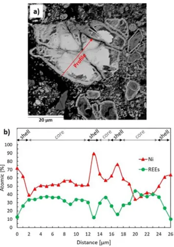
A high-magnification cross section of a P5-type particle with a representative core–shell structure and corresponding EPMA line profile are shown in Figure 2. Around the core (the lighter part on the micrographs), the shell is composed of a dense, thin layer (Figure 2b) covered by a porous matrix. The EPMA line profile (Figure 2d) reveals that the dense layer of the shell (the two points at 1.8 and 3.5 mm) contains, on average, 1.35 times more Ni and Co than that in the core (points at <1.8 and >4.7 mm). As for the porous matrix (point at 3.0 mm), it has high contents of La, Ce, and O of 23.9, 8.1, and 20.1 at%, respectively, whereas the Ni and Co con-tents drop to 8.8 and 1.1 at%, respectively (Fig-ure 2d).
The core–shell structure of P5-type particles is most likely linked to NiMH battery aging mecha-nisms. Indeed, the degradation of NiMH batteries is a complex process in which different mechanisms are at play, including corrosion of the hydrogen storage alloy. It is worth noting that the stability of the mis-chmetal alloy against corrosion can be impacted by the chemical composition of the alloy, among other parameters. According to the groups of Leblanc and B-uerlein, changes in corrosion rates as a function of alloy composition are mainly due to differences in
decrepitation tendencies.[34,35]Decrepitation, or
parti-cle pulverization, is caused by lattice expansion and contraction of the alloy during hydrogen absorption
Figure 1. SEM backscattered electron (BSE) cross sections of representative BM particles: P2 type (zone 1), P3 type (zone 2), P4 type (zone 3), and P5 type (zone 4).
Table 2. EPMA WDS range of atomic contents of P2 type, P3 type, P4 type and P5 type BM particles [at %].
Particle type Atomic content [%] (Ni,Co,Mn,Al):(REEs)
O Al K Mn Co Ni Pr Nd La Ce Total
P2 1.2 1.4 0 0 0.1 0.1 0.2 0.3 0.9 97.4 97.7 0 0 0 0 100
P3 2.0 8.1 0.2 0.4 0.2 1.4 0.1 0.4 2.9 7.3 62.0 93.6 0 0 0 0 92.0
P4 9.5 33.0 1.1 3.0 0 0.2 3.7 4.3 6.2 8.7 42.1 43.6 0.3 1.4 2.4 6.0 19.8 3.2 8.2 99.9 1.9 4.6
and desorption. The discrete volume changes produce local mechanical stresses that lead to cracking of the alloy grains, the generation of smaller particles, and the development of a
higher particle specific surface area.[34–36]Knowing that, from a
thermodynamic point of view, the oxidation of less noble metals, such as La, Nd, Pr, and Ce, in KOH cannot be
avoid-ed,[36] the higher the particle specific surface area the greater
the amount of corrosion scales. Therefore, there is a correlation between the decrepitation tendency of the mischmetal alloy and the corrosion of the particles. Consequently, alloy compo-sition can be optimized to achieve low lattice expansions during hydrogen intercalation. For example, Chartouni et al. stated that cobalt substitution in the mischmetal alloy had a stabilizing effect by reducing the cracking tendency of the alloy.[37]
Several studies in the literature report that corrosion scales form at the surface of the particles in strong-alkali media, re-tarding hydrogen diffusion rates and leading to battery
fail-ure.[15,21, 34–36,38–40] Maurel et al. analyzed TEM cross sections of
AB5 mischmetal cycled in KOH electrolyte, and suggested the
formation of three different corrosion layers due to solid-state diffusion: a metallic core different from that of the initial alloy, a continuous corrosion subscale up to 200 nm thick composed
of solid solutions of Ni and Co, and a surface layer of rare-earth hydroxide composed of 1.5 mm long needles embedded
in the corrosion subscale.[36] Nickel and cobalt sublayers were
also identified by the groups of Ikoma[38]and B-uerlein,[35]and
several other authors indicated that needle-shaped rare-earth hydroxides covered the surface of the alloy upon battery cy-cling in alkali media.[15,34–36,38]
Based on these consistent observations, we postulate that P4-type particles correspond to unused battery material (Figure 1, zone 3), whereas the core–shell structure of P5-type particles identified in the BM correspond to aged alloys (Figure 1, zone 4, and Figure 2). The nickel and cobalt sublayer identified in the literature corresponds to the dense layer of the shell of P5-type particles shown in Figure 2. The porous matrix rich in La, Ce, and O observed around P5-type particles (Figure 2c) may thus originate from the disintegration of the needle-like rare-earth hydroxide surface layer. Moreover, based on the observation of various cross sections of the BM sam-ples, there are proportionally many more P5-type particles than that of P4-type particles, which is consistent with the fact that most batteries are collected if fully spent.
On top of structural changes caused by corrosion of the anode during battery cycling, the thermolysis step is very likely
Figure 2. a) SEM BSE cross section of a P5 type BM particle with a core shell structure, b) first magnification of the core shell oxide structure, c) second mag nification of the core shell oxide structure, and d) corresponding EPMA WDS line profile [at %].
to induce structural and chemical evolutions of the mischmetal alloy. However, the impact of thermolysis linked to battery re-processing is related to more recent concerns than those of battery aging, and thus, is not yet documented in the litera-ture. Nevertheless, based on a thermodynamic study of the La Ni O ternary system by Zinkevich and Aldinger, it is very likely that thermolysis leads to the formation of the stable
La2NiO4 spinel.[41] Indeed, this lanthanum nickelate is stable
over a large range of oxygen partial pressure (typically 10@8atm<P
O2<10
@1atm), covering thermolysis operating
con-ditions. For Ni/(Ni, La) molar ratios greater than 0.5, the phase diagram indicates that the spinel phase is the first phase that forms from the oxidation of a Ni La alloy, followed by oxida-tion of nickel into NiO. The results of Zinkevich et al. could ex-plain both the high oxygen content observed at the core of P5-type particles (Table 2 and Figure 2d) and the NiO phase
detected by means of powder XRD.[41]
Altogether, the EPMA characterization is coherent with the initial constitution of NiMH batteries, and particles from the anode and cathode active mass, as well as current collectors have been identified and quantified. Thanks to this local parti-cle identification approach, it is thus possible to follow the leaching progress by comparing the particles identified in the initial BM powder with those in the solid leach residue over time.
Thermodynamic-based choice of pH for leaching experi-ments in HCl media
The choice of pH for leaching experiments in HCl was guided by thermodynamic calculations. Considering the complex phase composition of the initial BM powder, the system was
restricted to the system Ni–La–H2O–HCl because Ni and La are
the major elements in the BM. The Eh–pH diagrams calculated at 408C for La and Ni are presented in Figure 3a and b, togeth-er with the list of aqueous species and solid phases taken into account in Figure 3c. Calculation details are provided in the Ex-perimental Section.
As observed in Figure 3a, La is not stable in its metallic form in aqueous media. At pH,6.8 and 40 8C (or pH, 7.1 at 258C;
pH ,6.3 at 60 8C), La is fully dissolved, mainly as LaCl2+. At
higher pH, its stable form is the solid hydroxide La(OH)3.
As for Ni (Figure 3b), a lower pH is required to ensure its full
dissolution (pH ,4.2 at 408C) and Ni2+ is the aqueous
domi-nant species for all temperatures; the complex NiCl+ is present
to a minor degree. Above pH 4.2 at 40 8C, metallic nickel is
stable and is not oxidized by H+ ions. Nickel(II) is soluble up to
pH 6, and forms the solid hydroxide Ni(OH)2at higher pH.
Notably, solids composed of both Ni and La elements (LaNi5
and La2NiO4) do not appear on these diagrams, which means
that the main mixed phases of the battery are not stable under leaching conditions.
These preliminary calculations indicate that, for a solid/liquid (S/L) ratio of 15 wt%, both nickel and lanthanum elements should be soluble at pH 4 and below, regardless of their initial
redox state. At 4<pH<6, La and NiIIare soluble, but metallic
Ni is stable. At 6< pH< 6.8, La is stable in the aqueous phase, whereas all redox states of Ni are involved in solid phases. Above pH 6.8, no dissolution of these two major elements in the BM should occur. These calculations imply a strong influ-ence of pH on the leaching behavior of the BM, and suggest that tuning the pH value might allow the selective dissolution of La. Therefore, the influence of pH on leaching of the BM was studied over the pH range of 3 to 5.5, and pH 3 was used as a point of comparison for studying the influence of the type
of acid (HCl or H2SO4) on the leaching yields and rates with
re-spect to temperature.
Leaching experiment results
As detailed in the Experimental Section, BM leaching experi-ments were carried out in a 10 L pilot reactor. The results are presented in the following sections, starting with the influence of temperature, then pH, and finally the nature of the acid.
Figure 3. Calculated Eh pH diagram for a) La and b) Ni, in the quaternary system Ni La H2O HCl at 408C, with [La]=0.0965 molkgw 1(kilograms of water)
Influence of temperature
The influence of temperature on the leaching yields of La and Ni in HCl at pH 3 is shown in Figure 4a; similar behavior to that of La is obtained for Ce, Nd, and Pr. The experiment at 408C was repeated twice and demonstrated good repeatability of the leaching yields and total acid consumption: a difference of less than 3.1 and 5.4% for the leaching yields of Ni and La, respectively, and a relative difference of 1.2% for the acid con-sumption were obtained between both experiments after 6 h of leaching.
Regardless of the temperature, La (and other REEs) leaching yields increase gradually and converge to complete dissolution (Figure 4a) after 22 h. As for Ni, a leaching yield of 58% is reached after 22 h at 608C, and the yield decreases with tem-perature. The leaching in HCl at pH 3 is thus partially selective: a maximal La/Ni selectivity ratio of about 6.5 is obtained for all three temperatures, and the time at which this maximum is
reached greatly reduces with temperature (after 3 h at 258C, 1.5 h at 408C, and 36 min at 608C). The evolution of the leach-ing yield of La with respect to that of Ni at pH 3 is plotted in Figure 5. Considering that, thermodynamically, both La and Ni
are soluble in HCl–H2O under these conditions (Figure 3), the
fact that all experimental points are located above the bisect-ing line shows that the leachbisect-ing kinetics of REEs are faster than that of Ni. Moreover, all experimental points at pH 3 over-lap, which demonstrates a similar leaching mechanism, regard-less of temperature. At pH 3 in HCl, the temperature only en-hances the overall reaction kinetics and an increase of 358C (from 25 to 60 8C) decreases the leaching duration by a factor of about 3.
Evolution of the chemical composition of the solid leach res-idues after mineralization (Table S1 in the Supporting Informa-tion) indicates an overall enrichment in Ni and a depletion in REEs, with respect to the initial BM powder, which is in agree-ment with the ICP-OES analyses of the pregnant leach solution (PLS). Powder XRD analysis of all solid leach residues shows that the major phases present in the initial BM powder are still present even after 22 h of leaching at 60 8C, namely, Ni, NiO, and graphite (Figure S2 in the Supporting Information).
It is interesting to identify P2- and P5-type particles in the solid leach residue, knowing that they are the ones which con-tain the highest contents of Ni and REEs. According to SEM and EPMA characterizations, many P2-type particles (pure Ni) are still present (Figure 6, zone 5) in the solid leach residue after 22 h of leaching at 608C.
A striking observation is that the core–shell structures of P5-type particles identified in the initial BM powder are still clearly apparent in all solid leach residues. After 1 h of reaction in HCl at pH 3 and 608C, that is, shortly after the maximum La/Ni se-lectivity ratio is reached, the composition and morphology of particles shown in Figure 6, zones 1 and 2, illustrate the leach-ing mechanism. Accordleach-ing to the EPMA wavelength-dispersive
Figure 4. a) Influence of the temperature in HCl at pH 3 on the leaching yields of La (circles) and Ni (triangles). b) Influence of the pH in HCl at 408C on the leaching yields of La (circles) and Ni (triangles).
Figure 5. Leaching yield of La [%] expressed with respect to the leaching yield of Ni [%] for experiments carried out in HCl at various pH and tempera ture (the black line corresponds to a congruent dissolution of La and Ni).
spectroscopy (WDS) point analyses (Table 3, zone 1), the core of the dissolving particle contains about 30 at% REEs, whereas the intermediate layer and shell contain 2.6 and 3.3 at% REEs, respectively. Moreover, compared to the core, the shell of the particle contains high amounts of Ni (75.6 at%) and is enriched in Co (14.0 at%; Figure 6, zone 1, and Table 3), which is close to the composition of the shell of P5-type particles in the initial BM powder (Table 2). An EPMA concentration profile measured across a larger particle (Figure 7) provides evidence that the shell contains between 70 and 90 at% Ni and 10 and 20 at% REEs. Overall, these observations show that REEs dissolve pref-erentially to nickel from the core of the particles, and that nickel contained in the dense outer shell does not dissolve.
Such a leaching mechanism is also evidenced in the cross sections of the solid leach residue after 22 h of dissolution in
HCl at pH 3 and 608C, where the structure of the remaining particles is either a porous shell with a hollow core (Figure 6, zone 3) or a core–shell structure with an undissolved core (Figure 6, zone 4). The shells of the hollow particles appear to be porous, and thus, allow REEs to dissolve. According to EPMA analyses (Table 3), the shells of these hollow particles are composed of approximately 62.1 at % Ni, 8.9 at% Co, and less than 0.5 at% REEs. The shells of the particles with an undis-solved core have almost the same composition (Table 3), while their core contains 50.0 at% Ni, 7.2 at % Co, 40.4 at% O, and less than 1.5 at% REEs. These results indicate that the shells and nickel-rich cores of the remaining particles, originally from the spent active mass of the anode, have very slow leaching ki-netics in HCl at pH 3, similarly to the metallic nickel mesh of the cathode.
Figure 6. SEM BSE cross sections of particles in the solid leach residue obtained in HCl at pH 3 and 608C, after 1 h of leaching (zones 1 and 2) and after 22 h of leaching (zones 3 5).
Table 3. EPMA WDS point analyses of particles identified in Figure 6 [at %].
Region Composition [at %]
O Al K Mn Co Ni Pr Nd La Ce Total zone 1 21 15.19.2 1.60.2 0.00.3 3.60.1 9.36.5 42.644.1 0.21.5 0.45.2 10.30.9 12.71.2 97.467.6 3 4.2 0.0 0.1 0.2 14.0 75.6 0.2 0.4 1.6 1.0 97.5 zone 2 54 16.09.5 1.70.0 0.00.2 4.60.0 8.56.6 41.042.1 0.11.2 0.14.2 10.70.1 13.80.1 96.564.2 6 13.6 0.2 0.1 0.0 8.4 47.6 0.0 0.2 0.3 0.6 70.9 zone 3[a] 7 26.8 1.0 0.0 0.1 8.9 62.1 0.0 0.1 0.2 0.2 101.5 zone 4 89 24.540.4 0.90.8 0.00.1 0.10.1 7.29.6 50.063.2 0.00.0 0.10.1 0.91.1 0.50.5 100100 zone 5 10 1.2 0.0 0.0 0.0 0.31 98.0 0.0 0.0 0.0 0.0 100
Influence of pH
The influence of pH on the evolution of the leaching yields of REEs and Ni in HCl at 40 8C is shown in Figure 4b. After 22 h of leaching at 408C, the recovery yield of Ni decreases from 37.9% at pH 3 to only 11.9% at pH 5.5. Meanwhile, the La re-covery yield drops from 100% at pH 3 to 11.1% at pH 5.5. Sim-ilar leaching behavior as La is obtained for Ce, Nd, and Pr at pH 3 and 4, whereas at pH 5.5 Ce, Nd, and Pr have lower leach-ing yields than that of La of 8.0, 5.2, and 4.4%, respectively, after 22 h of leaching at 40 8C. As observed in Figure 5, at pH 5.5 and 408C, if the leaching yield of La is plotted against that of Ni, the experimental points are almost aligned with the bisecting line. According to our thermodynamic calculations
under these conditions, La and NiII (from the phases La
2NiO4
and NiO) are soluble, whereas metallic Ni should remain solid (Figure 3). Therefore, we hypothesized that the low leaching
yield obtained for nickel shows that NiII has slow leaching
ki-netics at pH 5.5, which consequently hinders the dissolution rate of REEs through the creation of a thicker diffusion layer than that at pH 3.
XRD analysis of the solid leach residues obtained at pH 4 and 5.5 at 408C in HCl after 22 h of leaching (Figure S3 in the Supporting Information) reveals that they are composed of the
same major phases as those present in the initial BM powder,
namely, Ni, NiO, CeO2, and graphite.
Figure 7. a) SME BSE cross section of a particle after 1 h of leaching in HCl at pH 3 and 608C. b) Corresponding EPMA WDS concentration profile obtained across the particle [at%].
Figure 8. Evolution of the leaching yields of K (squares), La (circles), and Ni (triangles) in HCl (blue) and H2SO4(green) at pH 3 and at a) 25, b) 40, and
Influence of the type of acid
The influence of the leaching agent (HCl or H2SO4) on
the dissolution of REEs, Ni, and K has been studied at pH 3 for temperatures ranging from 25 to 60 8C. Under these conditions, both acids are completely dissociated (pKa(HCl/Cl@)= 6.3, pKa(H2SO4/HSO4@)=
3.0, and pKa(H2SO4/SO42@)=2.0 at 258C).
Again, all REES (La, Ce, Nd, and Pr) exhibit similar leaching behavior. Thus, only La is considered in the following discussion. As illustrated in Figure 8a and b, at pH 3 and 25 or 408C, the leaching yield of Ni
follows similar trends in H2SO4 and in HCl: yields of
only 12.1 and 20.5 % are obtained after 5 h, respec-tively. At 608C, however, nickel is more reactive in
H2SO4than that in HCl (Figure 8c): the same quantity
is leached in 45 min in H2SO4 than that after 5 h in
HCl. It is worth noting that, for the experiment
car-ried out in H2SO4 at pH 3 and 608C, much greater
acid consumption and gas production were observed than that at 25 or 408C. The increase in gas
produc-tion, which is attributed to H2(g)generation, indicates
more reactive dissolution of metallic nickel with
in-creased temperature. The large difference in leaching behavior between 40 and 60 8C was also observed by Hosseini et al.,
who studied the leaching kinetics of NiO and NiFe2O4 from
nickel tailings in 4m H2SO4at temperatures ranging from 25 to
808C.[42]They measured an abrupt increase in the leaching rate
of nickel at 608C after 1 h of leaching, and attributed it to the fact that below 408C only simple oxides dissolved, whereas spinel phases only started to dissolve after 1 h at 608C, and the reaction kinetics were then controlled by chemical reac-tion, rather than by diffusion.[42]
The data compiled in Figure 8 indicate that, for all
tempera-tures, potassium precipitates in H2SO4 media shortly after all
BM powder has been added because the curve of the leaching yield has a negative slope after approximately 24 min. On the other hand, potassium is completely solubilized in HCl at pH 3 at any temperature. It is thus likely that La and other REEs co-precipitate with K because their recovery rates are first equiva-lent to those obtained in HCl (for t<24 min) and then lower as K starts to precipitate (Figure 8). At 258C, potassium precipita-tion stops after 3 h because the leaching yield remains
con-stant at 30%, which is equivalent to 0.024 mol L@1 of K
(Fig-ure 8a). After 3 h, a sharp increase in the La leaching yield is observed (Figure 8a) and reaches a final yield of about 61% after 22 h. At 408C, the precipitation of both K and La stops
after 3 h, leading to leaching yields of 47.1 (or 0.034 molL@1of
K) and 46.0% (or 0.039 mol L@1of La), respectively, which
indi-cates that a solubility limit is reached (Figure 8b).
Mineralization of the solid leach residues obtained after
leaching in H2SO4 at pH 3 indicates an increasing potassium
content with time, which is coherent with the results of PLS analysis. No traces of sodium were detected.
The powder XRD spectra of the leach residues obtained
after 30 min of leaching in H2SO4 at pH 3 and 25 or 40 8C are
almost equivalent to that of the initial BM powder, and no
ad-ditional diffraction peaks are observed (Figure S4 in the Sup-porting Information). This confirms the results of leaching yield analysis, which show that potassium precipitation does not start until all BM has been added, that is, after 24 min (Figure 8). As observed in Figure 9, the major phases of Ni, NiO, and graphite are still present, even after 22 h of leaching
in H2SO4 for temperatures up to 608C. It is worth noting that
the residue obtained after 22 h of leaching in H2SO4 at pH 3
and 258C contains minor phases of Ce0.75Nd0.25O1.875 and
Pr10OS14, which are absent at 40 8C (Figure 9). This shows that,
in H2SO4, the precipitation behavior changes between 25 and
408C.
Furthermore, for all solid leach residues shown in Figure 9, a pristine phase appears that could be ascribed either to NaLa(SO4)2·H2O or KLa(SO4)2·H2O. Because the BM powder does
not contain Na and demineralized water is used for the experi-ments, we conclude that the peaks correspond to the phase
KLa(SO4)2·H2O. Even if the XRD spectrum is not a perfect match
because all peaks are slightly shifted to the right, with respect to the reference, this could be due to a mixed crystal composi-tion. Indeed, several other lanthanide–potassium double sul-fates (K3M(SO4)3, K6M4(SO4)9, K7M3(SO4)8, K5M(SO4)4, and
K6+ 3nM4@n(SO4)9; M =La, Ce, Nd, or Pr) are reported in the
litera-ture.[14,43,44]Porvali et al. studied the precipitation of REEs from
strong sulfuric acid NiMH battery waste leachate by the
addi-tion of Na2SO4and also observed a precipitate of mixed crystal
composition with a structure close to that of the lanthanide– alkali double sulfate.[14]
SEM observations of cross sections of the solid residue
ob-tained after 22 h of leaching in H2SO4 at pH 3 and 40 8C, and
corresponding EPMA point analyses, are compiled in Figure S5 and Table S2 in the Supporting Information. Particles with core–shell structures and compositions similar to those ob-tained in HCl are detected (Figure S5 in the Supporting
Infor-Figure 9. Powder XRD spectra of the initial BM sample (black) and the solid leach resi dues after dissolution in H2SO4at pH 3 and 258C for 22 h (green), at pH 3 and 408C for
mation, zones 1–3). As illustrated in Figure S5 in the Support-ing Information, many precipitates were found around the un-dissolved particles (points 5–10) and contained, on average, 65.9 at% O, 12.7 at% S, 8.5 at% REEs, 8.3 at% Ni, 3.4 at% K, and 0.7 at% Co (Table S2 in the Supporting Information). These local chemical analyses confirm the conclusions drawn from XRD analysis that REEs and K have coprecipitated. They also provide evidence of the coprecipitation of nickel and cobalt, probably in the form of double Tutton’s salts, such as K2Ni(SO4)2·6H2O, K2Co(SO4)2·6H2O, or K2NixCo1@x(SO4)2·6H2O.[45–47]
The precipitation of nickel could at least partially explain the slow increase in aqueous nickel concentration measured in
H2SO4at pH 3 at 40 8C. Although it is not possible to determine
accurately the precipitate composition due to its complexity, it is assumed that the precipitates consist of a mixture of potassi-um–lanthanide double sulfates and K2NixCo1@x(SO4)2·6H2O.
Discussion
The BM leaching mechanisms can be discussed thanks to a combination of all of our results (initial BM analyses, equilibri-um calculations, evolution of the elemental concentrations in the PLS, and solid leach residue characterization by means of
XRD, SEM, and EPMA). Whether in HCl or H2SO4, metallic Ni,
which is identified as such in Figure 1, zone 1, and originating from the cathode current collector, dissolves according to Equation (1). Gas generation was also observed during the ex-periments.
Nið Þs þ 2Hþ! Ni2þþ H2 gð Þ ð1Þ
However, despite favorable thermodynamics, according to
the Eh–pH diagram at pH 3 (Figure 3b), a large part of nickel in
its metal form remains in the solid leach residue, as indicated in the X-ray diffractograms and by means of EPMA-WDS analy-ses (Figure 6, zone 5, and Table 3). Similar observations were
reported by the groups of Larsson[13] and Petranikova,[23] who
studied separately the leaching of anodes and cathodes from NiMH batteries in HCl media. These authors postulated that hy-drogen produced during the acid attack of nickel metal [Eq. (1)] desorbed slowly from nickel surfaces. Based on elec-tronic orbital considerations, Santos et al. also concluded that
the adsorbed hydrogen intermediate species, Had, implied in
the redox reaction (e.g., Had+Had=H2(g)or H++ Had+e@= H2(g))
significantly slowed down the dissolution of metallic nickel in
HCl media.[48] For H
2SO4media, a possible explanation for
hin-dered nickel leaching could be the formation of a passivation layer on the Ni surface in the form of NiO or NiOOH, as report-ed by authors who have studireport-ed the anodic passivation of bulk Ni in H2SO4media.[49–52]
Similarly, nickel contained in the Ni/Co porous shell of P5-type particles and the Ni/Co/O core of some P5-P5-type particles does not dissolve or has very slow leaching kinetics, which contributes to the selective leaching of REE relative to that of Ni. Indeed, in both acids, REE-containing particles (type P5), the core of which is mainly composed of lanthanum nickelates
La2NiO4, exhibit selective leaching behavior, as evidenced by
EPMA profiles such as that presented in Figure 7. The leaching rate of nickel is slower than that of REEs, resulting progressive-ly in a hollow structure, as illustrated in Figure 10. It is suggest-ed that dissolution of REEs [Eq. (2)] and their diffusion through the porous Ni/Co shell results in a shrunken core rich in REEs, whereas an intermediate layer depleted of REEs, but rich in Ni and O, remains and dissolves more slowly (Figure 10).
La2NiO4 sð Þþ 6Hþ! 2La3þþ NiOð Þs þ 3H2O ð2Þ
In HCl media, according to speciation obtained from ther-modynamic calculations and consistent with experimental re-sults, aqueous La forms soluble chloride compounds, such as
LaCl2+[Eq. (3)], whereas nickel dissolves mainly as Ni2+and, to
a lesser extent, NiCl+ [Eq. (4)]. As a consequence, the leached
elements remain in the aqueous phase.
La3þþ Cl@! LaCl2þ ð3Þ
Ni2þþ Cl@! NiClþ ð4Þ
On the contrary, in H2SO4 media, leached REEs precipitate in
the form of sulfates, REE2(SO4)3; this behavior has also been
re-ported elsewhere.[24,53,54] Furthermore, Zelikman et al. explain
that lanthanide sulfates tend to form lanthanide–alkali double
Figure 10. a) Schematic illustration of the proposed leaching mechanism of P5 type particles identified in Figure 2 in the initial BM sample powder, and b) the corresponding SEM BSE micrograph.
salts in the presence of K2SO4 or Na2SO4, according to
Equa-tion (5), in which M=K or Na and REE =La, Ce, Nd, or Pr.[53]
REE2ðSO4Þ3þ M2SO4! 2 REEMðSO4Þ2? x H2O ð5Þ
Lokshin et al. measured the solubilities of double alkali-metal (Na, K)–rare-earth (La, Ce) sulfates in solutions in sulfuric
acid at 208C. For instance, at 208C and low H2SO4
concentra-tions, the solubility of KLa(SO4)2·H2O and KCe(SO4)2·H2O is
0.015 mol L@1, which is close to the potassium concentration of
0.024 mol L@1measured at 25 8C after 3 h, which is the point at
which potassium precipitation stops (Figure 8a).[55] Thus, in
H2SO4media, part of the lanthanide ions form aqueous sulfate
species [Eq. (6)], whereas others precipitate with K to form lan-thanide–alkali metal double sulfates [Eq. (7)]. The main stable nickel species in H2SO4 media is NiSO4(aq)[Eq. (8)], but, as
evi-denced by our local characterization (Figure S5 and Table S2 in the Supporting Information), part of the nickel precipitates with K, according to Equation (9).
2La3þþ 3SO
42@! La2ðSO4Þ3 aqð Þ ð6Þ
La2ðSO4Þ3ðaqÞþ K2SO4ðaqÞþ x H2O ! 2 KLaðSO4Þ2? x H2OðsÞ ð7Þ
Ni2þþ SO
42@! NiðSO4Þð Þaq ð8Þ
NiðSO4ÞðaqÞþ K2SO4ðaqÞþ 6 H2O ! K2NiðSO4Þ2? 6 H2O ð9Þ
Conclusions
An industrial sample of spent NiMH battery powder, which was obtained by the thermomechanical treatment of a batch of 600 kg, was characterized for chemical and structural proper-ties. Chemical analysis revealed that the sample powder was mainly composed of 45 wt% Ni, 15 wt% REEs, and 13 wt% O, whereas XRD analysis demonstrated that the major crystalline phases consisted of Ni and NiO. A novel result was the quanti-tative EPMA-WDS analyses of cross sections of the powders, which helped to provide an overall description that was consis-tent with the initial battery constitution. Indeed, particles con-taining 97.4 at% Ni corresponded to the metallic nickel mesh of the cathode current collector and porous spherical particles rich in Ni and Co came from the cathode active mass. An inter-esting result was the identification of mischmetal particles with core–shell structures: at the core, the (Ni, Co, Mn, Al)/(La, Ce, Nd, Pr) molar ratio was 4.5, whereas the dense shell layer contained 1.35 times more Ni and Co than that in the core. Moreover, an oxide layer rich in REEs surrounded this dense shell. We attributed such particle morphology to NiMH battery aging mechanisms after cycling in KOH electrolyte, in which corrosion subscales concentrated in Ni and Co and REE hydrox-ide structures were known to form around the mischmetal par-ticles.
In view of a sustainable recycling process, a parametric study was carried out in a 10 L pilot-scale reactor to assess the influence of pH (3–5.5), temperature (25–60 8C), and type of
acid (HCl or H2SO4) on the leaching mechanisms of Ni and
REEs contained in the industrial battery powders.
Partial selectivity was evidenced in HCl at pH 3 for all tem-peratures. For instance, at 25 8C, 91.6 % of La and 17.2% of Ni leached after 6 h, leading to an aqueous La/Ni molar ratio of
5.31. In H2SO4media, a similar selective dissolution occurred at
25 and 408C, whereas nickel dissolution was enhanced at 608C. However, potassium present in the initial battery powder (about 2 wt% K) led to the in situ precipitation of REEs in the form of lanthanide–potassium double sulfates, as well as the precipitation of nickel and cobalt double salts; thus reducing their overall dissolution yields.
One of the reasons for the selective dissolution of REEs, with respect to Ni, was due to the kinetic inhibition of nickel metal
leaching, in both HCl and H2SO4, as already reported in several
studies. In the present work, thanks to local EPMA analyses of the solid leach residues, we also showed that specific leaching mechanism occurred in the core–shell mischmetal particles, in both acid media. The Ni- and Co-rich shell, originating from a corrosion subscale, remained undissolved, even after 22 h of leaching. The leaching mechanism of the interior of such parti-cles was of the “shrinking core” type, in which the leaching rate of REEs was faster than that of Ni. As dissolution proceed-ed, this resulted in a concentration gradient inside the core of the particles. These findings highlight the influence of battery anode aging phenomena on the leaching mechanisms of Ni and REEs from industrial samples of spent NiMH battery pow-ders.
Experimental Section
Initial raw material characterization
The BM powder was characterized for chemical content, phase de-termination, and morphological features. The material was mineral-ized at 2508C for 2 h in aqua regia (mixture of HCl 37 % and HNO3 65% in a 1:1 ratio), with a S/L mass ratio of 10%; a cooling system was used to condense vapors. The elemental content was deter-mined by means of ICP-OES (PerkinElmer Optima 8300), for the fol-lowing elements: Al, Cd, Ce, Co, Cu, Fe, La, Li, Mn, Nd, Ni, Pr, Zn, K, and Na. Oxygen and carbon contents were measured by using in-strumental gas analyzers (IGAs) equipped with IR detectors (EMGA 620 W LECO for oxygen and EMIA 820 V HORIBA for carbon). Phase composition was determined by means of powder XRD on a D8 BRUKER instrument in the q/2 q configuration and CuKa radiation (2q range of 20 808, with a wavelength of 1.5418 a). Cross sec-tions of the solid material were prepared by embedding the pow-ders in a nonconducting thermosetting resin (PolyFast, STRUERS) for hot molding (Mecapress 3, PRESI) and diamond-polished down to 1 mm (Mecatech 234, PRESI). Semiquantitative analyses of the cross sections were carried out by using a scanning electron micro-scope field-emission gun (SEM-FEG, JEOL JSM 7100F) equipped with an EDX Oxford ASDD X-Max detector. Quantitative analyses of the cross sections were performed with an EPMA (CAMECA SXFive FE) equipped with WDS detectors.
Pilot setup of the leaching experiments
The leaching tests were performed in a 10 L jacketed glass reactor equipped with a three-baffle mechanical stirrer. A constant mixing
rate of 400 rpm ensured the suspension of all particles. The tem-perature inside the reactor was regulated by using a HUBER Minis-tat 240 instrument. A mass of 1.2 kg of BM powder was added at a constant rate of 50 gmin 1in an initial volume of 8 L of demineral-ized water, leading to an initial S/L ratio of 15 %; the starting time (t 0) of the experiment was the beginning of BM addition. The pH of the solution in the reactor was regulated in the range of 3< pH<5.5, by using a PID controller connected to a pump and a stock container of leaching agent. Relative pH standard deviations were lower than :4% for all experiments. HCl (12m/12n) or H2SO4 (6m/12n) were used as leaching agents (reagent grade) for pH ad-justment and acid consumption was followed by measuring the mass of acid with a balance. The effects of three process parame-ters on leaching yields and mechanisms were studied up to 22 h: the influence of pH (3 5.5) at 40 8C in HCl, and the influence of temperature (25 608C) and type of acid (HCl or H2SO4) at pH 3. At the end of the runs, the remaining solid leach residue was filtered from the PLS by using a pneumatic filter press and the PLS was collected for further treatment.
To follow the evolution of the leaching yields, samples (5 mL) were taken at periodic time intervals, filtered through 0.45 mm syringe filters, and analyzed by means of ICP-OES. The resulting leaching yield for a given element, i, at time t, LYið Þ, is calculated accordingt to Equation (10):
LYið Þt 100 Cið ÞVmt totð Þt
BMwi ð10Þ
in which Cið Þ is the concentration of element i in the sample att time t (in gL 1), V
totð Þ is the total volume of solution (Ht 2O+added acid, in L), mBM is the initial mass of BM powder (in g), and wi is the mass fraction of element i in the initial BM powder.
In addition, for some experiments, four samples (&150 mL) were extracted at different times and filtered by using a Bechner system, to 1) measure the S/L ratio evolution; and 2) characterize the solid residues by means of XRD, SEM-FEG, EPMA, and ICP-OES. The con-sistency of the overall elementary mass balance was verified for one set of conditions (H2SO4(6m), pH 3, 408C, repeated twice) by comparing the analysis of the solid samples extracted with the Bechner system, the analysis of the aqueous solution, and the ini-tial BM composition.
Thermodynamic calculations
Thermodynamic calculations were carried out thanks to the geo-chemical software PHREEQC operated with PHREEPlot.[56] The ex-tended Debye Heckel b-dot equation of the LLNL model was used to calculate aqueous activity coefficients.[56] Thermodynamic data were taken from the 2017 version of the Thermoddem database[57] and completed to account for the thermodynamic properties of solid phases (La(OH)3,[58]LaNi5,[59]and La2NiO4[41]) and aqueous lan-thanide chloride compounds (LaCl2+, LaCl2+, LaCl3, and LaCl4 ),[60,61] valid in the temperature range 25 908C. Eh pH speciation dia-grams were calculated at 25, 40, and 608C, with La and Ni concen-trations corresponding to a 15 wt% S/L ratio (S is the solid BM and L is the HCl H2O liquid phase).
Acknowledgements
We wish to thank Sophie Gouy and Philippe De Parseval from the Centre de Micro-caract8risation Raimond Castaing for various
EPMA analyses, as well as Marie-Line de Solan-Bethmale from the Laboratoire de G8nie Chimique (LGC) for the SEM analyses, and C8dric Charvillat from the Centre Interuniversitaire de Re-cherche et d’Ing8nierie des Mat8riaux (CIRIMAT) for the powder XRD measurements.
Conflict of interest
The authors declare no conflict of interest.
Keywords: alkali metals · electrochemistry · nanoparticles · nickel · rare earths
[1] Deloitte Sustainability, British Geological Survey, MiniHres, Bureau de Re cherches G8ologiques et MiniHres, Research, Netherlands Organisation for Applied Scientific, Study on the Review of the List of Critical Raw Ma terials, Brussels, 2017.
[2] L. E. O. C. Rodrigues, M. B. Mansur, J. Power Sources 2010, 195, 3735 3741.
[3] P. Meshram, B. D. Pandey, T. R. Mankhand, Waste Manage. 2016, 51, 196 203.
[4] C. Pillot, The Rechargeable Battery Market and Main Trends 2016 2025, 2017.
[5] Trinomics, Study in Support of Evaluation of the Directive 2006/66/EC on Batteries and Accumulators and Waste Batteries and Accumulators, 2014. [6] European Union, European Innovation Partnership on Raw Materials: Raw
Materials Scoreboard, 2016.
[7] J. J. M. Nelson, E. J. Schelter, Inorg. Chem. 2019, 58, 979 990. [8] ADEME, 2017, 1 146.
[9] P. Subir, Understanding the Material Science of Battery We Use Every Day, found under http://www.tsijournals.com/articles/understanding the ma terial science of battery we use everyday.html.
[10] J. Nan, D. Han, M. Yang, M. Cui, J. Electrochem. Soc. 2006, 153, A101. [11] S. Al Thyabat, T. Nakamura, E. Shibata, A. Iizuka, Miner. Eng. 2013, 45, 4
17.
[12] V. Innocenzi, F. Veglik, J. Power Sources 2012, 211, 184 191.
[13] K. Larsson, C. Ekberg, A. Ødegaard Jensen, Waste Manage. 2013, 33, 689 698.
[14] A. Porvali, B. P. Wilson, M. Lundstrçm, Waste Manage. 2018, 71, 381 389.
[15] K. Young, B. Chao, Y. Liu, J. Nei, J. Alloys Compd. 2014, 606, 97 104. [16] A. Fernandes, J. C. Afonso, A. J. B. Dutra, Hydrometallurgy 2013, 133,
37 43.
[17] N. Tzanetakis, K. Scott, J. Chem. Technol. Biotechnol. 2004, 79, 919 926. [18] K. Korkmaz, M. Alemrajabi, a. C. Rasmuson, K. M. Forsberg, Metals 2018,
8, 1062.
[19] P. Zhang, T. Yokoyama, O. Itabashi, Y. Wakui, T. M. Suzuki, K. Inoue, Hy drometallurgy 1998, 50, 61 75.
[20] X. Yang, J. Zhang, X. Fang, J. Hazard. Mater. 2014, 279, 384 388. [21] F. Holmberg, Recycling of Nickel Metal Hydride (NiMH) Batteries: Charac
terization and Recovery of Nickel, AB5 Alloy and Cobalt, Chalmers Univer sity of Technology, 2017.
[22] S. Luidold, H. Antrekowitsch, EP 2 444 507 B1, 2012.
[23] M. Petranikova, I. Herdzik Koniecko, B. M. Steenari, C. Ekberg, Hydrome tallurgy 2017, 171, 128 141.
[24] L. Li, S. Xu, Z. Ju, F. Wu, Hydrometallurgy 2009, 100, 41 46.
[25] M. A. Rabah, F. E. Farghaly, M. A. Abd El Motaleb, Waste Manage. 2008, 28, 1159 1167.
[26] L. Pietrelli, B. Bellomo, D. Fontana, M. R. Montereali, Hydrometallurgy 2002, 66, 135 139.
[27] L. Pietrelli, B. Bellomo, D. Fontana, M. Montereali, Waste Manage. 2005, 25, 221 226.
[28] P. Meshram, B. D. Pandey, T. R. Mankhand, Hydrometallurgy 2015, 158, 172 179.
[29] D. A. Bertuol, A. M. Bernardes, J. A. S. Tenjrio, J. Power Sources 2009, 193, 914 923.
[30] A. R. Alonso, E. A. Perez, G. T. Lapidus, R. M. Luna Sanchez, Hydrometal lurgy 2014, 1, 277 289.
[31] P. Zhang, T. Yokoyama, O. Itabashi, Y. Wakui, T. M. Suzuki, K. Inoue, J. Power Sources 1999, 77, 116 122.
[32] C. Liu, Y. Deng, J. Chen, D. Zou, W. Su, Ind. Eng. Chem. Res. 2017, 56, 7551 7558.
[33] A. Porvali, V. Agarwal, M. Lundstrçm, Mining, Metall. Explor. 2019, 36, 979 991.
[34] P. Leblanc, B. Knosp, C. Jordy, P. Blanchard, J. Electrochem. Soc. 1998, 145, 860 863.
[35] P. B-uerlein, C. Antonius, J. Lçffler, J. Kempers, J. Power Sources 2008, 176, 547 554.
[36] F. Maurel, B. Knosp, M. Backhaus Ricoult, J. Electrochem. Soc. 2000, 147, 78 86.
[37] D. Chartouni, F. Meli, A. Zettel, K. Gross, L. Schlapbach, J. Alloys Compd. 1996, 241, 160 166.
[38] M. Ikoma, K. Komori, S. Kaida, C. Iwakura, J. Alloys Compd. 1999, 284, 92 98.
[39] X. Zhou, K. Young, J. West, J. Regalado, K. Cherisol, J. Alloys Compd. 2013, 580, S373 S377.
[40] L. Schlapbach, A. Seiler, H. C. Siegmann, F. Stucki, J. Less Common Met. 1980, 73, 145 160.
[41] M. Zinkevich, F. Aldinger, J. Alloys Compd. 2004, 375, 147 161. [42] S. A. Hosseini, S. Raygan, A. Rezaei, A. Jafari, J. Environ. Chem. Eng. 2017,
5, 3922 3929.
[43] M. S. Wickleder, Chem. Rev. 2002, 102, 2011 2087. [44] P. A. Degtiarev, J. Less Common Met. 1979, 68, 107 110.
[45] V. Manomenova, E. Rudneve, A. Voloshin, Russ. Chem. Rev. 2016, 85, 585 609.
[46] A. E. Voloshin, V. L. Manomenova, E. B. Rudneva, N. A. Vasilyeva, V. M. Masalov, A. A. Zhokhov, G. A. Emelchenko, J. Cryst. Growth 2018, 500, 98 103.
[47] N. A. Vasilyeva, D. Nuzhdin, M. A. Faddeev, V. V. Grebenev, V. A. Lykov, A. E. Voloshin, Crystallogr. Rep. 2016, 61, 304 307.
[48] E. Santos, P. Hindelang, P. Quaino, E. N. Schulz, G. Soldano, W. Schmick ler, ChemPhysChem 2011, 12, 2274 2279.
[49] T. Du, A. Vijayakumar, K. B. Sundaram, V. Desai, Microelectron. Eng. 2004, 75, 234 241.
[50] A. E. Sanli, A. Aytac, ECS Trans. 2012, 42, 3 22.
[51] M. Itagaki, H. Nakazawa, K. Watanabe, K. Noda, Corros. Sci. 1997, 39, 901 911.
[52] N. Sato, G. Okamoto, J. Electrochem. Soc. 1963, 110, 605 614.
[53] A. N. Zelikman, O. E. Krein, G. V. Samsonov, Metallurgy of Rare Metals, 1964.
[54] D. S. Todorovsky, M. M. Milanova, N. L. Minkova, C. Balarev, Monatsh. Chem. 1993, 124, 673 679.
[55] E. P. Lokshin, O. A. Tareeva, K. G. Ivlev, T. G. Kashulina, Russ. J. Appl. Chem. 2005, 78, 1058 1063.
[56] D. L. Parkhurst, C. A. J. Appelo, PHREEQC (Version 3) A Computer Pro gram for Speciation, Batch Reaction, One Dimensional Transport, and In verse Geochemical Calculations, 2013.
[57] P. Blanc, A. Lassin, P. Piantone, M. Azaroual, N. Jacquemet, A. Fabbri, E. C. Gaucher, Appl. Geochem. 2012, 27, 2107 2116.
[58] C. Ekberg, P. L. Brown, Hydrolysis of Metal Ions, Wiley VCH, Weinheim, 2016.
[59] N. P. Gorbachuk, V. B. Muratov, Powder Metall. Met. Ceram. 2005, 44, 467 471.
[60] J. Haas, E. Shock, D. Sassani, Geochim. Cosmochim. Acta 1995, 59, 4329 4350.
[61] E. L. Shock, H. C. Helgeson, Geochim. Cosmochim. Acta 1988, 52, 2009 2036.
![Table 1. Average chemical composition [wt%] of the industrial BM sample powder.](https://thumb-eu.123doks.com/thumbv2/123doknet/2945498.79638/3.892.457.822.366.658/table-average-chemical-composition-industrial-bm-sample-powder.webp)
![Table 2. EPMA WDS range of atomic contents of P2 type, P3 type, P4 type and P5 type BM particles [at %].](https://thumb-eu.123doks.com/thumbv2/123doknet/2945498.79638/4.892.74.833.1015.1117/table-epma-wds-range-atomic-contents-type-particles.webp)
![Figure 2. a) SEM BSE cross section of a P5 type BM particle with a core shell structure, b) first magnification of the core shell oxide structure, c) second mag nification of the core shell oxide structure, and d) corresponding EPMA WDS line profile [at %]](https://thumb-eu.123doks.com/thumbv2/123doknet/2945498.79638/5.892.109.782.97.631/figure-particle-structure-magnification-structure-nification-structure-corresponding.webp)
![Figure 3. Calculated Eh pH diagram for a) La and b) Ni, in the quaternary system Ni La H 2 O HCl at 408C, with [La]=0.0965 molkgw 1 (kilograms of water)](https://thumb-eu.123doks.com/thumbv2/123doknet/2945498.79638/6.892.77.818.811.1074/figure-calculated-diagram-quaternary-hcl-molkgw-kilograms-water.webp)

![Table 3. EPMA WDS point analyses of particles identified in Figure 6 [at %].](https://thumb-eu.123doks.com/thumbv2/123doknet/2945498.79638/8.892.71.823.591.797/table-epma-wds-point-analyses-particles-identified-figure.webp)