HAL Id: hal-02514790
https://hal.archives-ouvertes.fr/hal-02514790
Submitted on 22 Mar 2020
HAL is a multi-disciplinary open access
archive for the deposit and dissemination of
sci-entific research documents, whether they are
pub-lished or not. The documents may come from
teaching and research institutions in France or
abroad, or from public or private research centers.
L’archive ouverte pluridisciplinaire HAL, est
destinée au dépôt et à la diffusion de documents
scientifiques de niveau recherche, publiés ou non,
émanant des établissements d’enseignement et de
recherche français ou étrangers, des laboratoires
publics ou privés.
Methodologies for the optimal design of the Integrated
Modular Power Electronics Cabinet (IMPEC)
Xavier Giraud, Marc Budinger, Xavier Roboam, Hubert Piquet, M. Sartor, J.
Faucher
To cite this version:
Xavier Giraud, Marc Budinger, Xavier Roboam, Hubert Piquet, M. Sartor, et al.. Methodologies for
the optimal design of the Integrated Modular Power Electronics Cabinet (IMPEC). MEA 2015 More
Electric Aircraft, Feb 2015, Toulouse, France. �hal-02514790�
Methodologies for the optimal design of the Integrated
Modular Power Electronics Cabinet (IMPEC)
X.Giraud (1,2,3), M.Budinger (2), X.Roboam (3), H.Piquet (3), M.Sartor (2), J.Faucher (1) 1 : Airbus Operations SAS, 316 route de Bayonne, 31060 Toulouse Cedex 9, France
2 : Université de Toulouse, ICA (INSA, UPS, Mines Albi, ISAE), 135 av.de Rangueil, 31077 Toulouse, France 3 : Université de Toulouse, LAPLACE (CNRS/INPT/UPS), 2 Rue Camichel, 31071, Toulouse, France
Abstract Closely linked to the research on the more electrical aircraft, this paper deals with a new concept of electrical power distribution system called IMPEC for Integrated Modular Power Electronics Cabinet. The proposed methods aim at carrying out an optimal design of this new power center, the main variables being on one hand the number and size of power electronics modules and, on the other hand, reconfigurations between these modules and electrical loads.The formalization of the problem highlights that the designer must deal simultaneously with a combinatorial explosion and a multi-physical system sizing. The main objective of the study is to propose a methodological framework for solving this original optimal design problem. A heuristic-based algorithm is developed to solve this combinatorial optimization problem. A particular attention is paid to develop a formalized weight estimation procedure using generic sizing models. Finally a mapping is performed to identify the best solutions and to highlight the technological devices having the most significant impact on the complete system weight.
1. Introduction
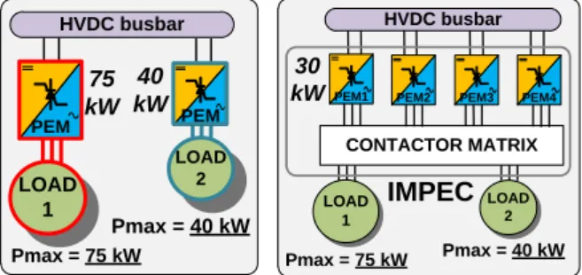
On traditional aircraft such as A320 or A330, systems are powered by 3 different energy vectors : pneumatic, hydraulic and electric. Among the technological enhancements required for the MEA (More Electrical Aircraft), power electronics is one of most important technology. With the MEA, power electronics modules need to supply high power systems consuming up to 100 kW (e.g the ECS - Environmental Control System). This significant change in terms of power demand levels requires to design innovative concept for the supply of electrical loads requiring power electronics devices [1]. As seen on the Figure 1 (left-hand side), aircraft loads requiring power electronics are traditionally supplied by a dedicated power electronics module (PEM). Several drawbacks are identified with this solution : reliability aspect (the PEM loss implies the load loss), cost aspect (the number of PEM references is equivalent to the load number), the low rate of PEM utilization (if the load is intermittent). The Integrated Modular Power Electronic Cabinet (IMPEC) has been designed to tackle all these drawbacks (Figure 1 right-hand side) [2].
The IMPEC structure is made of 2 main parts : a set of modular PEM providing power from HVDC bus and a contactor matrix ensuring the connexions between the PEMs and the loads. One PEM can supply any load at any time during the mission. Moreover one load can be supplied by one or several PEM at the same time.
The mutualisation of the PEMs through the contactor matrix enable to bring to 2 sorts of advantages: robustness against a PEM failure and flexibility according to the fluctuations of the load power
demands. This last advantage is illustrated on the Figure 2 showing that only 4 PEMs (30 kW rated) are required to supply the 2 loads since they do not consume their maximum power during the same operational case. HVDC busbar LOAD 1 LOAD 2 Pmax = 40 kW Pmax = 75 kW 75 kW PEM PEM 40 kW HVDC busbar CONTACTOR MATRIX 30
kWPEM1 PEM2 PEM3 PEM4
LOAD 1 LOAD 2 Pmax = 40 kW Pmax = 75 kW IMPEC
Figure 1 Traditional structure (left) – IMPEC (right)
HVDC busbar
LOAD
1 LOAD 2
30 kW 75 kW
PEM1 PEM2 PEM3 PEM4
Case n°1 : load n°1 at maximum power HVDC busbar LOAD 1 LOAD 2 40 kW 60 kW
PEM1 PEM2 PEM3 PEM4
Case n°2 : load n°2 at maximum power
Figure 2 Flexibility against power demand changes
2. Optimal design problematics
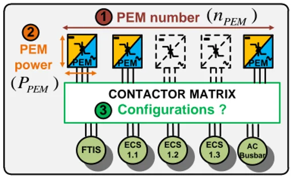
The present work defines methodologies in order to solve the optimal design of IMPEC. The main design objective is to minimize the overall system weight. 3 types of design variables are set : 1) number of PEM «n
PEM» 2) PEM power «P
PEM» 3) contactor matrix reconfiguration solution (Figure 3).CONTACTOR MATRIX Configurations ? FTIS ECS 1.1 ECS 1.2 ECS 1.3
PEM PEM PEM
AC Busbar PEM number 2 1 3 PEM power
)
(
n
PEM)
(
P
PEMFigure 3 Illustration of the design variables of the optimization design problem
Based on these design variables and due to the technical perimeter of the IMPEC concept, 2 axis of complexity appears for the optimal design:
- Axis 1 : multi-physical design since IMPEC is
made of several components (semiconductor devices, cold plates, heat exchanger,…) belonging to different physical fields (Figure 4).
- Axis 2 : combinatorial explosion due to the
capacity of the system to reconfigure itself for any operational case. For example, an IMPEC solution made of 7 PEM having to supply 5 loads leads to 27720 potential contactor matrix reconfiguration solutions (i.e combinations of “PEM-load” connections). As the designer shall cope with this choice number for several thousand of operational cases, a huge number of matrix reconfiguration solutions appears.
Cold plate Heat
exchanger Chassis Inductance Contactor Capacitor IGBT Thermal Electrical Mechanical 1 2 4 3 5 6 7
Figure 4 IMPEC components
3. Developed methodologies
To help the designer coping with this combinatory, an explicit and rapid sizing process is developed. The global process is cut into several sizing blocs: one for each component type. The N2D formalism is chosen in order to formalize this process (see Figure 5). By introducing design hypothesis, all loops are deleted between the different sizing blocs. Within each sizing bloc, simple relations such as analytical equations or surrogate models are used. These equations can be established beforehand by using high computation time demanding methods such as solvers or simulations.
Since the classical combinatorial optimization algorithms are not efficient due to the problem size, a
dedicated method is developed. This heuristic relies on 2 steps : 1) pre-processing enabling to define beforehand a set of physical features of the solutions (PEM number, contactor number, inductance number) 2) the successive launch of a greedy algorithm and a local search algorithm in order to define the contactor matrix reconfiguration. The performance of this innovative algorithm has been successfully validated on problems of different sizes.
max , PEM I max , L I Cold plates IGBT sw
F
Tp,m axTj,max m ax , _ ) (Tplo u t ∆Tech,2 Inductances max , OND P b L Wb cal I XX d XX th XX YY XX YY XX YY b c R R a , , , , , , cpW
IGBTW
LW
Hypothesis
System requirements
Unitary weight
cal I λ m ax , p T l p Q_ des T ∆ 1 2 7Figure 5 Part of the N2D of the IMPEC sizing process
4. Results
The complete methodology introduced above is employed to identify the most robust solution forms defined by the couple « (nPEM,PPEM)». The study is realized with different technology performance: IGBT power losses level ; weight of contactors, inductances and capacitors. Over 160 solutions forms created by the heuristic, the study shows that only 4 solution forms are optimal. A design of experiments, applied on these solution forms is carried out in order to quantify their linear sensibilities according to the technology performance. As shown by Figure 6, the results highlight that the weight of the interconnection components (contactor, inductance) are the main drivers capable to bring weight savings.
Figure 6 Linear sensitivities of the technology performance on the overall weight of one solution References
1. X. Roboam, New trends and challenges of electrical
networks embedded in “more electrical aircraft’, IEEE
International Symposium on Industrial Electronics, pp 26-31, 27-30, Gdansk, June 2011
2 L. Prisse, D. Ferer, H. Foch, A. Lacoste, New power
centre and power electronics sharing in aircraft, EPE