HAL Id: hal-00486751
https://hal.archives-ouvertes.fr/hal-00486751
Submitted on 26 May 2010
HAL is a multi-disciplinary open access
archive for the deposit and dissemination of
sci-entific research documents, whether they are
pub-lished or not. The documents may come from
teaching and research institutions in France or
abroad, or from public or private research centers.
L’archive ouverte pluridisciplinaire HAL, est
destinée au dépôt et à la diffusion de documents
scientifiques de niveau recherche, publiés ou non,
émanant des établissements d’enseignement et de
recherche français ou étrangers, des laboratoires
publics ou privés.
MIMO communications for inhome PLC networks:
measurements and results up to 100 MHz
Rehan Hashmat, Pascal Pagani, Thierry Chonavel
To cite this version:
Rehan Hashmat, Pascal Pagani, Thierry Chonavel. MIMO communications for inhome PLC networks:
measurements and results up to 100 MHz. ISPLC 2010 : 14th IEEE International Symposium on Power
Line Communications and its Applications, Mar 2010, Rio De Janeiro, Brazil. �hal-00486751�
Abstract— Power Line Communications (PLC) is used for information exchange over the lines installed for delivering the electrical power. Inhome PLC is a technology which delivers telecom services to every corner of a household through already existing electrical wiring. In recent years, PLC has emerged as a potential candidate for domestic high bit rate services. The current inhome PLC technology, based on Single-Input Single-Output (SISO) configuration, under achieves the capacity offered by the physical PLC channel. The inhome PLC channel offers multiple signal feed ports as, usually, it comprises of three wires: Phase, Neutral and Protective Earth. The measurements and results presented in this paper demonstrate that up to 90% enhancement in inhome PLC channel capacity is possible by using multiple-input multiple-output (MIMO) technique.
Index Terms—Channel transfer function, MIMO, Channel
capacity, Powerline communications
I. INTRODUCTION
HE PLC technology delivers information on electrical power lines. Generally the electrical power delivery networks are composed of three levels depending on voltage: transmission, distribution and utilization. Transmission and distribution are accomplished by three phase networks with a voltage level of 11 kV or above. At the utilization stage the industry uses three-phase, 380 volts; while for households single-phase, 230 volts is a common practice. Three-phase networks are made up of three conductors, one for each phase. There may be a fourth conductor for neutral. These conductors are sufficiently isolated from each other, either by air or by protective insulation. Therefore, such networks inherently offer space diversity. In the PLC literature, various Space-Time Coding (STC) techniques have been discussed, generally for 3-phase industrial networks, in [5] [6] [7] [8] [9] [10]. In most developed countries, the inhome single phase electrical wiring consists of three copper wires: live or phase
(P), neutral (N) and protective earth (PE). The existing inhome PLC systems, however, utilize only P and N for signal transportation. As a result, the inhome PLC technology remained confined to SISO configuration. Nevertheless, recently MIMO for single phase, inhome PLC has been reported in [1] [4]. The inclusion of PE offers multiple signal transmit/receive ports: P-N, P-PE and N-PE. A MIMO scenario thus created can be exploited for the enhancement of PLC channel capacity.
We performed MIMO transfer function measurements on various inhome PLC channels. We started with an experimental PLC network disconnected from the AC mains and then replicated the measurements on a real-life inhome PLC network.
In this paper, section II describes the theoretical background of MIMO technique, section III shows the measurements, calculations and results for experimental PLC network, section IV presents the measurements and results for real-life inhome PLC network and section V is for conclusions.
II. MIMOSYSTEM MODEL
MIMO communication is a well established technique in radio transmission systems and can be equally applicable to PLC by replacing transmit and receive antennas with signal feed and receive ports, and the radio channel with electrical wiring.
Figure 1. A typical MIMO communication system
Consider a MIMO transmission channel with M transmit and N receive antennas, as shown in figure 1. The channel can be described by a N x M channel transfer matrix H. The entry hn,m
MIMO Communications for Inhome PLC Networks:
Measurements and Results up to 100 MHz
Rehan Hashmat
(1), Pascal Pagani
(1), Thierry Chonavel
(2)(1) Orange Labs, 2 av. Pierre Marzin, 22300 Lannion, France
e-mail: rehan.hashmat@orange-ftgroup.com, pascal.pagani@orange-ftgroup.com
(2) Telecom Bretagne, CS 83818, Technopôle Brest Iroise, 29238 Brest Cedex, France
e-mail: thierry.chonavel@telecom-bretagne.eu
of matrix H represents the channel coefficient from the mth transmit antenna element to the nth receive antenna element. The signal yn received at the nth receive antenna can be given
as yn= n M m nm
x
w
h
∑
=+
1 m (1) where xm is the signal sent by the mth transmit antenna and wnis the noise received at the nth receiver. The channel input-output relationship can be described as
w
Hx
y
=
+
(2) The described MIMO system is power constrained at the transmitter, that is, the total transmitted power is not more thanP watts. The capacity C of MIMO channel is defined as the maximum data rate that can be transmitted over the channel with a probability of error arbitrarily close to zero [].
)]
det(
[log
2 NHH
HM
I
C
=
+
ρ
(3) where ρ denotes the signal-to-noise ratio (SNR) at each receive antenna and H indicates a Hermitian transpose. For M=N, the equation (3) simplifies to∑
=+
=
r i iM
C
1 2(
1
)
log
ρ
λ
(4) where r is the rank of HHH andλ
iis the ith eigenvalue of HHH obtained by eigenvalue decomposition (EVD).
AD
A
HH
H=
(5) Here A is the matrix composed of the eigenvectors of HHH, and D is the matrix whose diagonal entries are the eigenvalues. For M≠N, singular value decomposition (SVD) is used instead of EVD. The SVD is given by the following equation:V
U
H
=
∆
(5) where U and V are unitary matrices, and ∆ is the matrix whose diagonal entries are the singular values of H. Singular values, denoted byδ
, are related to eigenvalue as shown by Eq (6).
δ
=
λ
(6) The matrix D is useful in calculating the parameter R among channel coefficients hn,m, which gives an idea of the correlationamong the channel coefficients.
∑
=
)
(
)
(
max,
D
diag
D
diag
R
(7)R varies from 0.5 (low correlation) to 1 (high correlation) as the diagonal entries of D move from 0.5 to 1.0.
III. EXPERIMENTAL PLC NETWORK
A. PLC Channel Transfer Function Measurement
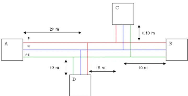
The first set of PLC MIMO-channel measurements was performed on an experimental PLC network at Orange Labs whose schematic diagram is shown in figure 2.
Figure 2. Schematic diagram of experimental PLC network A, B, C and D represent electric sockets. Six distinct combinations of four sockets provide six network branches: A-B, A-C, A-D, B-C, B-D and C-D. Each branch can be treated as a PLC MIMO channel. It should be noted that the network under test is neither connected to AC mains of 230 volts nor earthed. Such an isolated network is useful to understand the behavior of the physical wires and effect of branching in the absence of external factors such as impulsive noise, effect of appliance plugging and de-plugging, effect of load mismatching etc.
The PLC channel consists of P, N and PE wires. It provides three possible ports, P-N, P-PE and N-PE, for differential signals transmission and reception.
Figure 3. Splitter used for MIMO measurements (Schematic view)
Figure 3 shows the schematic diagram of a splitter for MIMO measurements that we have designed and realized at Orange Labs. It is a passive device which simply pairs up P, N and PE into P-N, P-PE and N-PE ports. The splitter provides an interface between the PLC network and the Vector Network Analyzer (VNA).
three differential feed ports is not physically possible. However, a 2x2 MIMO system, with two differential feed and receive ports is realizable. For this purpose, we performed three 2x2 MIMO measurements on each of the six network branches (figure 4a). Channel Transfer Functions (CTF) h11,
h12, h21 and h22 are measured (by measuring S21) at 1601
discrete frequencies from 2 MHz up to 100 MHz by a VNA. It should be noted that h11 and h22 are co-channels, and h12 andh21
are cross-channels.
(a) (b)
Figure 4. (a) A 2x2 PLC MIMO channel (using N-PE and P-N ports). (b) N-PE_P-N 3-dimensional MIMO channel matrix These CTF measurements are then arranged into 2 (rows) x 2 (columns) x 1601 (layers) 3-dimensional channel matrices, as shown in figure 4b, for further analysis.
Figure 6 shows typical co-channel and cross channel transfer functions for the PLC channel A-B. We have observed that transfer functions are stronger for co-channels as compared to cross channels.
Figure 5. Typical channel transfer functions
B. PLC MIMO-Channel Capacity Calculation
In the general case of a MIMO system comprising of M emitter ports and N receiver ports, the channel matrix H(f) can be written as:
( )
( )
( )
( )
( )
( )
( )
( )
( )
( )
=
f
h
f
h
f
h
f
h
f
h
f
h
f
h
f
h
f
h
f
H
M N N N M M , 2 , 1 , , 2 2 , 2 1 , 2 , 1 2 , 1 1 , 1L
M
O
M
M
L
L
(8)where hnm(f) represents the complex channel transfer
coefficient from the mth emitter to the nth receiver, at a frequency f. Transmission channels represented by hn,m with
m=n are called co-channels, and those represented by hn,m with
m≠n are called cross-channels. MIMO capacity of radio channels is a well established fact [2]. The MIMO capacity CMIMO for a multi-port channel is calculated by using the
equation: CMIMO=
( )
∑ ∑
= =+
∆
N n i R n t n i n T t n x xn
f
N
f
f
P
f
1 1 2)
)
(
)
(
1
(
log
λ
bits/sec (9) whereλ
i( )
f
n denotes the eigenvalues of HHH at a givenmeasurement frequency, H stands for channel matrix and superscript H represents a Hermitian transpose of H. Similarly,
x T
P
( )
f
n is the transmitted power,x R
N
( )
f
n is the noise at the receiver,n
t is the number of transmit ports, N is the number of points on the frequency axis and∆
f
is the frequency step size. Thex T
P
( )
f
n mask, as shown in figure 6,recommended by the regulation authorities has been selected, according to which, a
x T
P
of -50 dBm/Hz is transmitted from 0 to 30 MHz and -80 dBm/Hz onwards up to 100 MHz.Figure 6. Transmit power (PTx) mask for PLC systems
For noise, we have considered a colored Gaussian noise model instead of a flat noise, see figure 7. The Power Spectral Density (PSD) of
x R
N
( )
f
n is a model described in ICT OMEGA project [3]. This model was extracted from measurements on practical PLC networks. It closely resembles the noise model mentioned in [11].x R
N
( )
f
n is represented by equation 10. x RN
( )
f
n =1
2+
10
−15.5f
mW/Hz (10)For the calculation of SISO capacity CSISO, we selected the
channel transfer function measured for P-N port. That is, the measurement for which the signal is transmitted and received between P and N wires. The SISO capacity is determined by equation 11. CSISO =
∑
=+
∆
N n R n n n Tf
N
f
h
f
P
f
x x 1 2 2)
)
(
)
(
)
(
1
(
log
bits/sec (11) whereh
(
f
n)
denotes the P-N port channel transfer function. Finally, the MIMO capacity was divided by the SISO capacity to obtain the MIMO capacity gain.MIMO Capacity Gain=
SISO MIMO
C
C
(12)
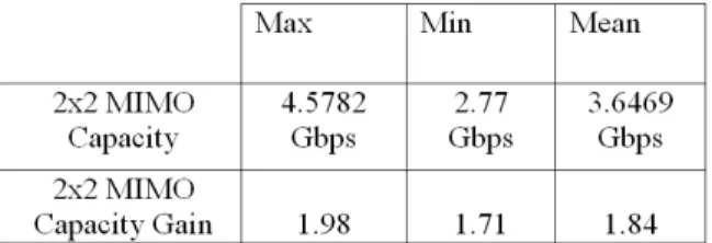
The average MIMO capacity gain of eighteen (six NPE-PN, six PN-PPE and six NPE-PPE) 2x2 configurations is found out to be around 1.88, or in other words an almost 88% increase compared to the existing PLC systems which utilize only two wires. Some important results are summarized in Table 1.
Table 1. Max, min and mean values of MIMO capacity and MIMO capacity gain over 18 measurements.
MIMO capacity, SISO capacity and capacity gain versus frequency are depicted in figure 8. It can be observed that MIMO and SISO capacities are higher for 2-30 MHz band, which corresponds to a higher transmit power. Moreover, they increase with frequency within this band. It can be attributed to decaying
x R
N
( )
f
n level. Interestingly, the capacity gain is almost independent of the frequency.Figure 8. MIMO capacity, SISO capacity and capacity gain
We used equation 12 to obtain a sense of correlation among MIMO channels. We found, generally, a high correlation among the channels as shown by the cumulative distribution function (CDF) in figure 9.
Figure 9. CDF indicating a sense of correlation among 2x2 MIMO channels.
IV. REAL-LIFE INHOME PLC NETWORK
A. PLC Channel Transfer Function Measurement
Same PLC MIMO-channel measurements were replicated on a real-life inhome PLC network connected to AC mains of 230 volts (live network) and duly earthed. Therefore, practical aspects such as impulsive noise, effect of appliance plugging and de-plugging, topological anomalies, effect of load mismatching etc. are present in the measured data.
Figure 10. Typical transfer functions for live PLC network
Figure 10 shows a co-channel and a cross-channel transfer function of a typical 2x2 MIMO PLC channel. We observed that co-channels are not necessarily stronger than cross- channels.
B. PLC MIMO-Channel Capacity Calculation
The algorithm and method used for live PLC channel capacity calculation is the same as presented in section II.B. Table 2 shows some representative results.
Table 2. Max, min and mean values of MIMO capacity and MIMO capacity gain.
Figure 11 shows MIMO capacity, SISO capacity and capacity gain as a function of frequency. Figure 12 shows the CDF of parameter R among MIMO channels. We observe that these results are not far from the ones found for experimental network. 0 1 2 3 4 5 6 7 8 9 10 x 107 0 10 20 30 40 50 60 frequency (Hz)
MIMO Capacity, SISO capacity and Capacity gain
2x2 MIMO capacity (Bits/Hz) SISO capacity (Bits/Hz) Capacity gain
Fig 11. MIMO capacity, SISO capacity and capacity gain
Fig 12. CDF indicating a sense of correlation among 2x2 MIMO channels.
V. CONCLUSION
The contemporary inhome single phase electrical power delivery network consists of three wires. Therefore, multiple signal feeding ports are available in most inhome PLC channels. We performed two channel matrix measurement campaigns, first on an experimental network the other on real network. Subsequent channel capacity calculations have suggested that the inhome PLC channel capacity can be increased by almost 85% through MIMO technique. The PLC MIMO technology is thus a promising candidate for the enhancement of the throughput for wired inhome communications. Future research will focus on additional experimental analysis, including the refinement of the noise model, and on the development of signal processing strategies
to optimally exploit the capacity offered by PLC MIMO. REFERENCES
[1] L. Stadelmeier, S. Dietmar, et al., “MIMO for Inhome Powerline Communications,” 7th International ITG
Conference on Source and Channel Coding, Ulm, Germany, Jan. 2008.
[2] K. Yu and B. Ottersten, “Models for MIMO Propagation Channels, a Review,” Wireless Communications and
Mobile Computing, Special Issue on Adaptive Antennas and MIMO Systems, vol. 2, no. 7, pp. 653-666, Nov. 2002.
[3] Seventh Framework Programme: Theme 3 ICT-213311 OMEGA, Deliverable D3.2, “PLC Channel Characterization and Modelling,” Dec. 2008.
[4] D. Schneider, J. Speidel, L. Stadelmeier and D. Schill, “Precoded Spatial Multiplexing MIMO for Inhome Power Line Communications,” IEEE Global Telecommunications Conference, New Orleans, LO, Nov. 2008.
[5] L. Hao and J. Guo. “A MIMO-OFDM Scheme over Coupled Multi-conductor Power-Line Communication Channel,” International Symposium on Power Line
Communications, Pisa, Italy, March 2007.
[6] L. Lampe, R. Schober and S. Yiu, “Distributed Space-Time Coding for Multihop Transmission in Power Line Communication Networks,” IEEE Journal on Selected
Areas in Comm., vol.24, no.7, pp. 1389-1400, July 2006. [7] L. Lampe, R. Schober and S. Yiu, “Multihop
Transmission in Power Line Communication Networks: Analysis and Distributed Space-Time Coding,” 6th IEEE
Workshop on Signal Processing Advances in Wireless Communications, New York, NY, June 2005.
[8] C. L. Giovaneli, P. Farrell and B. Honary, “Improved Space-Time Coding Applications for Power Line Channels,” International Symposium on Power Line
Communications, Kyoto, Japan, March 2003.
[9] M. Kuhn, D. Benyoucef and A. Wittneben, “Linear Block Codes for Frequency Selective PLC Channels with Colored Noise and Multiple Narrowband Interference,”
IEEE Vehicular Technol. Conference, Birmingham, AL, May 2002.
[10] C. L. Giovaneli, J. Yazdani, P. Farrell and B. Honary, “Application of Space-Time Diversity/Coding For Power Line Channels,” International Symposium on Power Line
Communications, Thessaloniki, Greece, March 2002. [11] D. Benyoucef, “A New Statistical Model of the Noise
Power Density Spectrum for Powerline Communication,”
International Symposium on Power Line